Language selection

Search

Patent 2307418 Summary

Third-party information liability

Some of the information on this Web page has been provided by external sources. The Government of Canada is not responsible for the accuracy, reliability or currency of the information supplied by external sources. Users wishing to rely upon this information should consult directly with the source of the information. Content provided by external sources is not subject to official languages, privacy and accessibility requirements.

Claims and Abstract availability

Any discrepancies in the text and image of the Claims and Abstract are due to differing posting times. Text of the Claims and Abstract are posted:

  • At the time the application is open to public inspection;
  • At the time of issue of the patent (grant).
(12) Patent: (11) CA 2307418
(54) English Title: FLUSH MOUNT POWER RECEPTACLE WITH INTEGRAL WALL PLATE
(54) French Title: PRISE D'ALIMENTATION ENCASTREE AVEC PLAQUE MURALE INTEGREE
Status: Deemed expired
Bibliographic Data
(51) International Patent Classification (IPC):
  • H01R 13/502 (2006.01)
  • H01R 13/436 (2006.01)
  • H02G 3/12 (2006.01)
  • H02G 3/14 (2006.01)
(72) Inventors :
  • DESILETS, PIERRE (Canada)
  • RATHBUN, LEONARD C. (United States of America)
  • SPANEDDA, JOSEPH (United States of America)
  • TANSI, HAKKI M. (United States of America)
(73) Owners :
  • LEVITON MANUFACTURING CO., INC. (United States of America)
(71) Applicants :
  • LEVITON MANUFACTURING CO., INC. (United States of America)
(74) Agent: RIDOUT & MAYBEE LLP
(74) Associate agent:
(45) Issued: 2007-12-18
(22) Filed Date: 2000-05-02
(41) Open to Public Inspection: 2000-11-05
Examination requested: 2005-04-28
Availability of licence: N/A
(25) Language of filing: English

Patent Cooperation Treaty (PCT): No

(30) Application Priority Data:
Application No. Country/Territory Date
09/306,666 United States of America 1999-05-05

Abstracts

English Abstract

An integral wall plate and power receptacle are provided for flush mounting on an electrical box or support. In that the wall plate and receptacle are made of insulating material the grounding of the wall plate is not required. The power receptacle includes a number of chambers into which contacts are selectively placed. Identification tabs on the contacts and keyways on the walls of the chambers limit insertion of the contacts to selected chambers and orient the contacts. The wall plate provides a smooth transition from the receptacle to thinned edges which receive mounting fasteners. An insert covers the base members and retains the contacts in their respective chambers while providing a smooth finished look to the wall plate.


French Abstract

Une plaque murale et une prise d'alimentation intégrantes sont prévues pour le montage encastré sur une boîte électrique ou un support. Parce que la plaque murale et la prise sont en matériau isolant, il n'est pas nécessaire de mettre à la terre la plaque murale. La prise d'alimentation comprend un certain nombre de chambres dans lesquelles les contacts sont placés sélectivement. Des onglets d'identification sur les contacts et les rainures sur les murs des chambres limitent l'insertion des contacts dans les chambres sélectionnées et orientent les contacts. La plaque murale fournit une transition en douceur de la prise avec les bords amincis qui reçoivent les fixations de montage. Une pièce rapportée couvre les éléments de base et retient les contacts dans leurs chambres respectives, tout en conférant un aspect fini lisse à la plaque murale.

Claims

Note: Claims are shown in the official language in which they were submitted.


We claim:


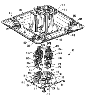
1. A flush mount power receptacle comprising:
a) a base member formed of insulating material having a plurality of
separate chambers extending from a first end to a second end;
b) a wall plate formed of insulating material and attached to said base
member adjacent said first end and extending beyond said base member;
c) said wall plate having a plurality of mounting apertures to selectively
receive therethrough a fastener to flush mount said power receptacle to a
supporting surface; and
d) an insert formed of insulating material adapted to be coupled to said base
member at said first end to partially close said separate chambers, wherein
said
wall plate is defined by a bottom surface and a top surface and four side
edges and
said top surface tapers from a central portion of said top surface to each of
said
four side edges.


2. A flush mount power receptacle, as defined in Claim 1, wherein said wall
plate has a recess adjacent said central portion and said base member to
receive
therein said insert so that a top surface of said insert is flush said top
surface of
said wall plate at said central portion.


3. A flush mount power receptacle, as defined in Claim 1 or 2, further
comprising:
a) at least two apertures in said base member at said first end; and
b) at least two locking tabs, one for each of said at least two apertures,
extending from a bottom surface of said insert, each of said at least two
locking
tabs engaging an associated one of said at least two apertures in said base
member
to fasten said insert to said base member.


12


4. A flush mount power receptacle, as defined in any one of Claims 1 to 3,
wherein said mounting apertures comprise four slots, two first slots open to a
first
side edge and two second slots open to a second side edge and a ridge about
each
of said first and second slots to receive the head of a fastener passed
through one
of said first and second slots.


5. A flush mount power receptacle, as defined in any one of Claims 1 to 3,
wherein said mounting apertures comprise four keyhole apertures, two first
keyhole
apertures adjacent a first side edge and two second keyhole apertures adjacent
a
second side edge, each of said first and second keyhole apertures comprising
an
entry aperture and a slot extending from said entry aperture and a ridge about

each of said first and second keyhole slots to receive the head of a fastener
passed
through one of said keyhole first and second slots.


6. A flush mount power receptacle, as defined in any one of Claims 1 to 3,
wherein said mounting apertures comprise:
a) four slots, two first slots open to a first side edge and two second slots
open to a second side edge adjacent said first side edge and a first ridge
about
each of said first and second slots to receive the head of a fastener passed
through
one of said first and second slots; and
b) four keyhole apertures, two first keyhole apertures adjacent a third side
edge and two second keyhole apertures adjacent a fourth side edge, each of
said
first and second keyhole apertures comprising an entry aperture and a slot
extending from said entry aperture and a second ridge about each of said first
and
second keyhole slots to receive the head of a fastener passed through one of
said
first and second slots.


7. A flush mount power receptacle as defined in any one of Claims 1 to 6,


13


further comprising: a plurality of electrical contacts, wherein each one of
the
electrical contacts is in a respective one of said separate chambers.

8. A flush mount power receptacle, as defined in Claim 7, wherein each of said

plurality of electrical contacts has discrete identification tabs thereon.

9. A flush mount power receptacle, as defined in Claim 8, wherein the walls
defining said separate chambers have keyways therein to permit entry of the
identification tabs of only a single electrical contact type and serve to
orient said
electrical contact with respect to said base member.

10. A flush mount power receptacle, as defined in Claim 9, wherein there are
two
identification tabs, one on each of two parallel spaced apart edges of said
electrical
contacts.

11. A flush mount power receptacle, as defined in Claim 10, wherein each
identification tab can take one of two discrete positions to provide four
possible
combinations.

12. A flush mount power receptacle, as defined in Claim 11, wherein the walls
defining said separate chambers have keyways therein to permit entry of the
identification tabs of only a single electrical contact type and serve to
orient said
electrical contact with respect said base member.

13. A flush mount power receptacle, as defined in any one of Claims 7 to 12
wherein said insert has a top surface and a bottom surface and a plurality of
retainers, one for each of said separate chambers, extending from said bottom
surface whereby when said insert is assembled to said base member said
retainers
each enter an associated separate chamber to retain each of said electrical
contacts

14


within said separate chambers.

14. A flush mount power receptacle, as defined in any one of Claims 7 to 13,
wherein said insert has one opening adjacent each of said separate chambers to

permit the insertion of a prong of an electrical plug into each of said
electrical
contacts.

15. A flush mount power receptacle, as defined in Claim 14, wherein said
openings have a shape and placement to admit only the prongs of a particular
type
of electrical plug.

16. A flush mount power receptacle, as defined in any one of Claims 1 to 15
wherein said base member has a central aperture and said insert has an
associated
central aperture whereby a fastener can be passed through said central
aperture in
said insert and into said central aperture in said base member to fix said
insert to
said base member.

17. A flush mount power receptacle, as defined in any one of Claims 1 to 16,
wherein said base member, said wall plate and said insert are each formed of a

plastic material.

18. A flush mount power receptacle, as defined in Claim 17, wherein said wall
plate is molded to said base member.

19. A flush mount power receptacle, as defined in Claim 17, wherein said wall
plate is attached to said base member by bonding agents, adhesives or sonic
welding.


20. A flush mount power receptacle comprising:
a base member having a plurality of separate chambers extending from a
first end to a second end,
a plurality of electrical contacts, each electrical contact being located in a

respective one of the separate chambers; and
a wall plate attached to the base member, the wall plate being defined by top
and bottom surfaces and four side edges, the top surface having a generally
flat
central portion adjacent and extending beyond the first end, wherein the front

surface tapers from the central portion of the front surface to each of the
four side
edges, the wall plate having a plurality of mounting apertures to selectively
receive
therethrough fasteners to flush mount the power receptacle to a supporting
surface.

21. A flush mount receptacle as defined in claim 20 wherein at least some of
said
mounting apertures extend through tapering portions of the front surface.

22. A flush mount power receptacle, as defined in claim 20 or 21, wherein said

mounting apertures comprise at least two mounting slots open to a first side
edge,
and at least two keyhole apertures adjacent a second side edge, each of said
keyhole apertures comprising an entry aperture and a slot extending from said
entry aperture.

23. A flush mount power receptacle, as defined in claim 22, wherein the
mounting slots open to the first side edge each include a respective ridge
recessed
from the top surface to receive the head of a fastener passed therethrough,
and the
keyhole aperture slots each includes a respective ridge recessed from the top
surface to receive the head of a fastener passed therethrough.

16


24. A flush mount power receptacle, as defined in claim 22 or claim 23,
wherein
said first and second side edges are opposite side edges of the wall plate.

25. A flush mount power receptacle as defined in any one of claims 20 to 24
wherein the base member and wall plate are formed from an insulating plastic
material.

26. A flush mount power receptacle as defined in any one of claims 20 to 25
wherein the base member has four of the separate chambers, wherein two of the
chambers have straight slot-like apertures defined at the first end to receive

straight prongs of a plug, one of the chambers has an L-shaped aperture
defined at
the first end to receive a generally L-shaped prong of the plug and one of the

chambers has a U-shaped aperture defined at the first end to receive a
generally U-
shaped prong of the plug.

27. A flush mount power receptacle as defined in any one of claims 20 to 25
wherein the base member has four of the separate chambers, wherein the
chambers each have a respective aperture at the first end configuring the
power
receptacle as a NEMA (National Electrical Manufacturers Association) 14-30R
receptacle.

28. A flush mount power receptacle as defined in any one of claims 20 to 25
wherein the base member has four of the separate chambers, wherein the
chambers each have a respective aperture at the first end configuring the
power
receptacle as a NEMA (National Electrical Manufacturers Association) 14-50R
receptacle.

29. A flush mount power receptacle having a generally flat central receptacle
surface defining a plurality of plug apertures that each communicate with a

17


respective chamber containing an electrical contact, the power receptacle
including
a wall plate having opposite facing first and second surfaces that meet at
four side
edges, the first surface having a central portion surrounding the central
receptacle
surface, wherein the first surface tapers from the central portion thereof to
each of
the four side edges, the wall plate having a plurality of mounting apertures
extending through tapering portions of the first surface for receiving
fasteners to
flush mount the power receptacle to a supporting surface.

30. A flush mount power receptacle, as defined in claim 29, wherein said
mounting apertures comprise at least two mounting slots open to a first side
edge,
and at least two keyhole apertures adjacent a second side edge, each of said
keyhole apertures comprising an entry aperture and a slot extending from said
entry aperture.

31. A flush mount power receptacle, as defined in claim 30, wherein the
mounting slots open to the first side edge each include a respective ridge
recessed
from the first surface to receive the head of a fastener passed therethrough,
and
the keyhole aperture slots each includes a respective ridge recessed from the
first
surface to receive the head of a fastener passed therethrough.

32. A flush mount power receptacle, as defined in claim 30 or claim 31,
wherein
said first and second side edges are opposite side edges of the wall plate.

33. A flush mount power receptacle as defined in any one of claims 29 to 32
wherein the plug apertures include two straight slot-like apertures to receive

straight prongs of a plug, an L-shaped aperture to receive a generally L-
shaped
prong of the plug and a U-shaped aperture to receive a generally U-shaped
prong
of the plug.

18


34. A flush mount power receptacle as defined in any one of claims 29 to 32
wherein the plug apertures are configured in a NEMA (National Electrical
Manufacturers Association) 14-30R format.

35. A flush mount power receptacle as defined in any one of claims 29 to 32
wherein the plug apertures are configured in a NEMA (National Electrical
Manufacturers Association) 14-50R format.

36. A flush mount power receptacle as defined in any one of claims 29 to 35
wherein the central portion of the first surface is generally flat and
parallel to the
central receptacle surface.

37. A flush mount power receptacle as defined in claims 36 wherein the central

portion of the first surface is flush with the central receptacle surface.

38. A flush mount power receptacle as defined in any one of claims 29 to 37
including a base member that defines four of the chambers and which extends
from
the second surface of the wall plate, wherein the central receptacle surface
is
located at a first end of a base member.

39. A flush mount power receptacle as defined in claim 38 wherein the base
member and wall plate are each formed from an insulating plastic material.
40. A flush mount power receptacle as defined in any one of claims 29 to 39
including an insert located in a central recess in the first surface of the
wall plate,
the central receptacle surface being provided by the insert.

41. A flush mount power receptacle as defined in any one of claims 20-28 or
claims 38 and 39 wherein an insert is secured to one end of the base member,
the
19


insert having a inner surface with a plurality of retainers, one for each of
the
chambers, whereby when the insert is secured to the base member the retainers
each enter an associated one of the chambers to retain each of the electrical
contacts within the chambers.


Description

Note: Descriptions are shown in the official language in which they were submitted.


CA 02307418 2000-05-02

FLUSH MOUNT POWER RECEPTACLE WITH INTEGRAL WALL PLATE
BACKGROUND OF THE INVENTION

Field of the Invention

The invention is directed to the field of power receptacles and more
particularly to
a flush mount power receptacle with an integral wall plate which does not have
to be
grounded.

Description of the Prior Art

A typical prior art device includes a base member of insulating material into
which electrical contacts are placed and closed by a cap of insulating
material. The base
member is mounted in an aperture of a metal mounting plate and riveted
thereto. A metal
strap extends from the rivet adjacent to the ground contact to the ground
contact to

ground the metal mounting plate. Slots and keyhole apertures permit the
mounting plate
to be mounted to an electrical box or support. The cap extends beyond the
mounting
plate. The extension of the cap and the difference in materials and color make
the device
appear unfinished.

SUMMARY OF THE INVENTION

The invention is directed to a flush mount power receptacle with integral wall
plate. A base member is formed with a plurality of separate chambers extending
from a
first end to a second end into which are placed electrical contacts. The
contacts are held
in place in the chambers by retainers on the back surface of an insert coupled
to the base


CA 02307418 2007-06-18

member by locking tabs and a fastener extending through the insert into the
base member.
A wall plate is molded onto or otherwise attached to the base member and
extends
beyond it to cover an electrical box or support to which the receptacle is
mounted. A
recess in the wall plate adjacent the base member permits the insert to be
positioned flush
with the top surface of the wall plate in the central region of the wall
plate. The wall

plate is tapered from the central region to each of the four side edges to
provide a smooth
transition from the receptacle to a mounting surface. A plurality of slots and
keyhole
apertures permit the wall plate to be mounted to an electrical box or support.
In that the
wall plate is made of insulating material as is true of the body member no
grounding strap
is required. Wheri the insert is in place, the wall plate provides a pleasing,
finished
appearance.

The electrical contacts are each provided with two identification tabs that
mate
with key ways in the walls of the separate chambers so that only a particular
electrical
contact type can be placed within each chamber and each contact admitted is
properly
oriented. Slots in the insert permit only the correctly shaped and oriented
prongs of an
electrical plug to be inserted into the electrical contacts. It is an object
of this invention
to provide a novel flush mount power receptacle with integral wall plate.

According to one aspect there is provided a flush mount power receptacle that
includes a base member having a plurality of separate chambers extending from
a first
end to a second end. The base member has a plurality of electrical contacts,
each
electrical contact being located in a respective one of the separate chambers.
The
receptacle has a wall plate attached to the base member, the wall plate being
defined by
top and bottom surfaces and four side edges, the top surface having a
generally flat
central portion adjacent and extending beyond the first end, wherein the front
surface
tapers from the central portion of the front surface to each of the four side
edges, the
wall plate having a plurality of mounting apertures to selectively receive
therethrough
fasteners to flush mount the power receptacle to a supporting surface.

2


CA 02307418 2007-06-18

According to another aspect of the invention is a flush mount power receptacle
having a generally flat central receptacle surface defining a plurality of
plug apertures
that each communicate with a respective chamber containing an electrical
contact, the
power receptacle including a wall plate having opposite facing first and
second surfaces
that meet at four side edges, the first surface having a central portion
surrounding the
central receptacle surface, wherein the first surface tapers from the central
portion thereof
to each of the four side edges, the wall plate having a plurality of mounting
apertures
extending through tapering portions of the first surface for receiving
fasteners to flush
mount the power receptacle to a supporting surface.

Other features of the invention will be pointed out in the following
description and claims and illustrated in the accompanying drawings, which
disclose, by
way of example, the principles of the invention, and the best modes which are
presently
contemplated for carrying them out.

BRIEF DESCRIPTION OF THE DRAWING

In the drawings in which similar elements are given similar reference
characters:
FIG. I is a top plan view of a power receptacle and mounting plate according
to
the prior art.

FIG. 2 is a side elevational view of the device of FIG. 1.

FIG. 3 is a top plan view of a flush mount power receptacle with integral wall
plate constructed in accordance with the concepts of the invention.

FIG. 4 is a side elevational view of the device of FIG. 3.

FIG. 5 is a top plan view of the base member of the device up FIG. 3 with the
insert removed to show details of the internal chambers.

3


CA 02307418 2000-05-02

FIG. 6 is a front right perspective view of the base member of FIG. 5.
FIG. 7 is a front left perspective view of the base member of FIG. 5.

FIG. 8 is top plan view of the base member of FIG. 5 showing the keyways
therein and the contacts which can be inserted into each chamber of the base
member.
FIG. 9 is an exploded, top perspective view of the device of FIG. 3.

FIG. 10 is an exploded bottom, perspective view of the device of FIG. 3.

FIG. 11 is a top perspective view of a further insert, which, can be used with
the
device of FIG. 3.

FIG. 12 is a bottom perspective view of the insert of FIG. 11.
DESCRIPTION OF THE PREFERRED EMBODIMENTS

Turning now to FIGS. 1 and 2 a power receptacle 10 with mounting plate 12,
according to the prior art is shown. Power receptacle 10 is made up of a base
14 which
contains chambers (not shown) into which are placed electrical contacts (not
shown). A
cap 16 is coupled to the base 14 once the contacts are in place in the
chambers. The
diameter of cap 16 is greater than the diameter of base 14 to provide a step
18. The cap
16 is coupled to the base 14 once the contacts are in place in the chambers.
The diameter
of cap 16 is greater than the diameter of base 14 to provide a step 18. The
cap contains
slots 20, 22 and 24 and a rounded aperture 26 to receive the prongs of an
electrical plug
(not shown). Four rivet apertures are placed in the cap 16 to receive rivets
28 which
fasten the cap 16 and base 14 to mounting plate 12. The step 18 rests on the
front surface
of the mounting plate 12 to position the base 14 and cap 16 with respect to
the mounting
plate 12. A grounding strap 30 is coupled by a rivet 28 to the mounting plate
12. The

4


CA 02307418 2007-06-18

free end of the grounding strap 30 is connected to the ground contact within
the base 14
(not shown) so that a grounding conductor coupled to the ground contact is
also coupled
to grounding strap 30 and thus the mounting plate 12 is grounded. A series of
slots 32
extend inwardly from the side edges 34 and 36. The slots 32 on side edge 34
are open
whereas the slots 32: on side edge 36 are closed by removable knock-outs 38. A
series of
keyhole apertures 40 are adjacent but spaced apart from side edges 42 and 44.
Each of
the keyhole apertures 40 is made up of an entry aperture 46 and a slot 48
extending
therefrom and communicating with entry aperture 46. The keyhole apertures 40

along side edge 44 are closed by removable knock-outs 50. As shown by FIG. 2,
the cap
16 extends above the top surface of mounting plate 12, and this coupled with
the
difference in materials between the cap 16 and mounting plate 12 makes the
receptacle
appear unfinished.

Referring now to FIGS. 3 to 10 a flush mount power receptacle 60 with integral
wall
plate 66 constructed in accordance with the concepts of the invention is
shown. Power
receptacle 60 has a base member 62 which contains a number of separate
chambers 64 to
receive electrical contacts therein as will be described below. Coupled to the
base

member 62 is a wall plate 66 having a generally flat central portion 68 (see
FIG. 4) and
tapering smoothly to each of the four side edges 70, 72, 74 and 76. The wall
plate 66

may be molded to the base member 62 or it may be attached thereto by the use
of bonding
agents, adhesives, sonic welding or the like. A recess 78 (see FIG. 9) in
central portion
68 is arranged to receive an insert 80 so that the top flat surface 82 of
insert 80 is flush
with the top surface of the remainder of central portion 68. A plurality of
apertures (see
FIG. 3) extend through insert 80 so that the prongs of an appropriate
electrical plug (not


CA 02307418 2000-05-02

shown) can be inserted through such apertures and into engagement with the
electrical
contacts in chambers 64. In FIG. 3 the apertures required for a NEMA 14-30R
plug and
receptacle is shown. Two straight apertures 84 receive the straight prongs of
a NEMA
14-30R plug, while U-shaped aperture 86 receives the generally U-shaped ground
prong
and the L-shaped aperture 88 receives the generally L-shaped prong. In FIG. 11
insert 90
has apertures arranged according to NEMA 14-50R. Three straight apertures 92
receive
the straight prongs of the NEMA 14-50R plug (not shown) while U-shaped
aperture 94
receives the generally U-shaped ground prong. The apertures through an insert
can be
arranged to conform to many other NEMA standard plug and receptacle
combinations.

Extending from the bottom surface 96 of insert 80 are four locking tabs 98, as
best
shown in FIG. 9, each of which is arranged to pass through a corresponding
locking
aperture 100 in the floor of recess 78 and grip the rear surface of the rim
102 (see FIG.

10) about the base member 62. To initially align and orient the insert 80 with
the base
member 62, a fin 104 extending from the bottom surface 96 of the insert 80
(see FIG. 10)
mates with an aperture 106 in the base member 62 (see FIG. 5). Unless the fin
104 is
aligned with aperture 106 the insert 80 cannot be assembled to base member 62.
To
complete the assembly of the insert 80 to the base member 62 a self-taping
screw 108 is
passed through assembly aperture 110 in insert 80 and into aperture 112 in the
base
member 62. The assembly aperture 110 is counter-sunk to permit the head of
screw 108
to be flush with the top surface 82 of insert 80 when the screw 108 is in its
final position.
The aperture 112 has a diameter less than the diameter of the self-taping
screw 108 and
the screw 108 cuts a thread into the walls defining aperture 112 to prevent
removal of the
screw 108 while holding the insert 80 and base member 62 in assembly. Because
the

6


CA 02307418 2007-06-18

wall plate 66 and the insert 80 are formed of insulating material such as
natural or
synthetic rubber, plastics or the like, there is no need to ground the wall
plate 66 and the
grounding strap has been omitted.

To mount the power receptacle 60 with integral wall plate 66 to an electrical
box or
support surface (not shown) a series of slots and keyhole apertures are placed
adjacent the
side edges of wall plate 66. Two elongate slots 114 are placed adjacent each
of the side
edges 70 and 72. Each of the slots 114 has a ridge 116 about all of the slot
114 except the
entry 118. A knock-out 120 covers the slots 114 and only the slots 114 to be
used have
their knock-outs 120 removed. The ridges 116 are engaged by the underside of
fasteners
passed through slots 114. The ridges 116 permit the fastener heads (not shown)
to be
recessed below the surface of the wall plate 66 but securely grip the wall
plate 66. Side
edges 74 and 76 each have two keyhole apertures 122 adjacent but spaced from
the side
edges 746, 76, respectively. Each keyhole aperture 122 has an entry aperture
124 from
which extends a slot 126. A ridge 128 extends about the slot 126. A knock-out
130

covers each of the keyhole apertures 122 and knock-outs 130 are removed as
required.
The ridges 128 serve the same purpose as ridges 116 of slots 114.

Contacts (see FIGS. 9 and 10) are placed in the Chambers 64 in accordance with
their function and the plug/receptacle configuration. Contacts 140 are
arranged to receive
the flat straight prongs of an electrical plug. Each contact 140 is generally
U-shaped
having at one end two jaws 142 between which is placed a flat, straight prong
of an
electrical plug. The ends 144 of the jaws 142 are outwardly directed as shown
in FIGS. 9
and 10 to facilitate entry of the prong between jaws 142. At the opposite end
of Contact
140 is placed a screw operated conductor clamp 146. The bared end of an
electrical

7


CA 02307418 2000-05-02

conductor (not shown) is inserted between a bridge 148 and the end of a screw
150. As
the screw 150 is tightened it forces the bared end of the conductor against
the bridge 148
thus retaining the conductor in the conductor clamp 146. Contact 152 is
similar to
contact 140 except the jaws 154 are initially spread apart because of the
width of the
ground prong of an electrical plug. The jaws 154 are outwardly deflected by
the ground
prong of the plug which securely grips the sides of the ground prong of the
plug. Contact
156 is similar to contact 140 except that jaw 158 is as wide as jaw 142 but
jaw 160 is
about one half of the width of jaw 142. This permits contact 156 to grip one
leg of the L-
shaped prong of the plug. Each of the contacts 140 and 152 have stabilizing
bars 162 on
both jaws 142 and 154, respectively, and contact 156 has a stabilizing bar 162
only on
jaw 158. The stabilizing bars 162 each engage a positioning rib on the side
walls of the
chambers 64 to support the contacts in the desired position within its
respective Chamber
64.

Each of the contacts 140, 156, 140 and 152 have two identification (ID) tabs
164
adjacent the screw operated conductor clamp 146 (see FIG. 8). ID tabs 164a,
164b, 164c
and 164d extend along a top edge of the contacts 140, 156, 140 and 152 while
ID tabs
164e, 164f, 164g and 164h extend along the spaced apart parallel bottom edge
of the
contacts 140, 156, 140 and 152. The ID tabs on each edge can take one of two
possible
positions as shown by ID tabs 164e and 164f, thus providing four discrete
combinations.
These ID tabs 164 in conjunction with keyways to be described below, are used
to
prevent the entry of a contact into a chamber 64 unless it matches the chamber
64
configuration and orients the jaws 142, 154, 158 and 160 correctly for the
prongs of the
electrical plug to be inserted.

8


CA 02307418 2000-05-02

FIGS. 5 to 8 depicts base member 62 showing the chambers 64a, 64b, 64a and
64c. Chambers 64a have a top internal rib 166 which defines a keyway 168 and a
bottom
internal rib 170 which defines a keyway 172. Only a contact having ID tabs
164a and
164e in the positions of keyways 168 and 172 will be permitted to enter cavity
164a and
then only when the ID tabs 164a and 164e are aligned with keyways 168, 172
(see FIG.
8). Positioning ribs 174 on the side walls of the chambers 64a, 64b, 64a and
64c in
conjunction with stabilizing bars 162 position the contact in its respective
chambers and
prevent movement of the contacts when the plug blades are inserted. Chamber
64b has a
top internal rib 176 which defines a keyway 178 and a bottom internal rib 180
which
defines a keyway 182. Only contact 156 has ID tabs 164b and 164f which can be
aligned
with keyways 178 and 182 thus permitting contact 156 to enter chamber 64b in
its correct
orientation. Similarly, chamber 64c has a top internal rib 184 which defines a
keyway
186 and a bottom internal rib 188 which defines a keyway 190. Ground contact
152 has
ID tabs 164d and 164h in positions corresponding to keyways 186, 190 and can
be
inserted in chamber 64c properly oriented. To retain the contacts 140, 156,
140 and 152
in their respective chambers 64a, 64b, 64a and 64c a series of retainers is
used as shown
in FIG. 10. The retainers have complimentary shapes to the apertures in the
insert 80 and
top edges which engage the free ends of the contacts to hold the contacts in
the correct
position. Retainers 192 are rectangular with a straight slot 194 and a top
edge 196
thereabout. The free ends of contacts 140 engage edges 196 to hold contacts
140 in place
and slot 194 permits flat, straight prongs to be inserted through slots 194
into

contacts 140. Retainer 198 is L-shaped with an L-shaped slot 200 and a top
edge 202. An
additional positioning tab 204 is provided for contact 156. The ends of the
jaws 158, 160
9


CA 02307418 2007-06-18

of contact 156 will engage top edge 202 of retainer 198 to hold the contact
156 in place
while permitting an L-shaped prong of a suitable plug to be inserted through L-
shaped
slot 200 into contact 156. U-shaped retainer 206 has a U-shaped slot 208 and a
top edge
210. The ends of contact 152 will engage top edge 210 to fix the position of
contact 152
and the slot 208 will permit the U-shaped ground prong of a plug to enter slot
208 and be
positioned between jaws 154 of contact 152.

To assemble the flush mount power receptacle 60 with integral wall plate 66
the
following sequence is followed. A base member 62 with a wall plate 66 attached
is
positioned such that the cavities 64a, 64b, 64a and 64c are oriented as shown
in FIG. 5.
Next the contacts 140 are placed in cavities 64a by aligning the ID tabs 164a
and 164e
with the keyways 168, 172. This is followed by inserting contact 156 into
cavity 64b
using ID tabs 164b and 164f in keyways 178, 182. The second contact 140 is
arranged to
put ID tabs 164c and 164g in keyways 168 and 172, respectively. Finally,
contact 152 is
inserted into cavity64c with ID tabs 164d and 164h entering keyways 186, 190.
This
sequence of inserting the contacts into base member 62 is for illustrative
purposes and the
contacts 140, 156 and 152 may be inserted into base member 62 in any desired
order.
Once the contacts 140, 152 and 156 are in place the insert 80 is positioned
over recess 78
with fin 104 of insert 80 aligned with aperture 106 in the base member 62. In
such
position the retainers 192, 198, 192 and 206 enter their associated cavities
64a, 64b, 64a
and 64c. A downward push on the top surface 82 of insert 80 causes the locking
tabs 98
to enter their respective slots 100 and engage the underside of lip 102. The
assembly is
completed by placing a self- taping screw 108 in aperture 110 of the insert 80
and driving
it downwardly with a hammer or the like into aperture 112 of base member 62.


CA 02307418 2000-05-02

The interior surface 208 of the wall plate 66 has raised ledges 210 about each
of
the slots 114 and raised ledges 212 about each of the keyhole apertures 122 to
prevent
over tightening of fasteners which are inserted in slots 114 and keyhole
apertures 122 and
cracking of the wall plate 66.

FIGS. 11 and 12 show an insert 90 arranged to receive an electrical plug with
three flat, straight prongs and a U-shaped ground prong. The third flat,
straight prong
replacing the L-shaped prong of FIGS 1 to 10. The retainer 214 is generally
rectangular
and has a slot 216 and a top edge 218. Top edge 218 engages the free end of a
contact
140. The assembly of insert 90 to a body member 62 will be the same as set
forth with
respect to insert 80.

While there have been shown and described and pointed out the fundamental
novel features of the invention as applied to the preferred embodiments, as
are presently
contemplated for carrying them out, it will be understood that various
omissions and
substitutions and changes of the form and details of the devices illustrated
and in their
operation may be made by those skilled in the art, without departing from the
spirit of the
invention.

11

Representative Drawing
A single figure which represents the drawing illustrating the invention.
Administrative Status

For a clearer understanding of the status of the application/patent presented on this page, the site Disclaimer , as well as the definitions for Patent , Administrative Status , Maintenance Fee  and Payment History  should be consulted.

Administrative Status

Title Date
Forecasted Issue Date 2007-12-18
(22) Filed 2000-05-02
(41) Open to Public Inspection 2000-11-05
Examination Requested 2005-04-28
(45) Issued 2007-12-18
Deemed Expired 2017-05-02

Abandonment History

Abandonment Date Reason Reinstatement Date
2006-05-02 FAILURE TO PAY APPLICATION MAINTENANCE FEE 2006-05-09

Payment History

Fee Type Anniversary Year Due Date Amount Paid Paid Date
Registration of a document - section 124 $100.00 2000-05-02
Application Fee $300.00 2000-05-02
Maintenance Fee - Application - New Act 2 2002-05-02 $100.00 2002-04-09
Maintenance Fee - Application - New Act 3 2003-05-02 $100.00 2003-04-22
Maintenance Fee - Application - New Act 4 2004-05-03 $100.00 2004-04-30
Request for Examination $800.00 2005-04-28
Maintenance Fee - Application - New Act 5 2005-05-02 $200.00 2005-04-28
Reinstatement: Failure to Pay Application Maintenance Fees $200.00 2006-05-09
Maintenance Fee - Application - New Act 6 2006-05-02 $200.00 2006-05-09
Maintenance Fee - Application - New Act 7 2007-05-02 $200.00 2007-04-26
Final Fee $300.00 2007-10-03
Maintenance Fee - Patent - New Act 8 2008-05-02 $200.00 2008-04-07
Maintenance Fee - Patent - New Act 9 2009-05-04 $200.00 2009-04-07
Maintenance Fee - Patent - New Act 10 2010-05-03 $250.00 2010-04-07
Maintenance Fee - Patent - New Act 11 2011-05-02 $250.00 2011-04-18
Maintenance Fee - Patent - New Act 12 2012-05-02 $250.00 2012-04-16
Maintenance Fee - Patent - New Act 13 2013-05-02 $250.00 2013-04-15
Maintenance Fee - Patent - New Act 14 2014-05-02 $250.00 2014-04-15
Maintenance Fee - Patent - New Act 15 2015-05-04 $450.00 2015-04-13
Owners on Record

Note: Records showing the ownership history in alphabetical order.

Current Owners on Record
LEVITON MANUFACTURING CO., INC.
Past Owners on Record
DESILETS, PIERRE
RATHBUN, LEONARD C.
SPANEDDA, JOSEPH
TANSI, HAKKI M.
Past Owners that do not appear in the "Owners on Record" listing will appear in other documentation within the application.
Documents

To view selected files, please enter reCAPTCHA code :


To view images, click a link in the Document Description column. To download the documents, select one or more checkboxes in the first column and then click the "Download Selected in PDF format (Zip Archive)" or the "Download Selected as Single PDF" button.

List of published and non-published patent-specific documents on the CPD .

If you have any difficulty accessing content, you can call the Client Service Centre at 1-866-997-1936 or send them an e-mail at CIPO Client Service Centre.


Document
Description 
Date
(yyyy-mm-dd) 
Number of pages   Size of Image (KB) 
Representative Drawing 2000-10-27 1 27
Drawings 2000-05-02 11 239
Abstract 2000-05-02 1 20
Description 2000-05-02 11 462
Claims 2000-05-02 4 143
Cover Page 2000-10-27 1 57
Claims 2007-06-18 9 299
Description 2007-06-18 11 467
Representative Drawing 2007-11-21 1 28
Cover Page 2007-11-21 1 59
Assignment 2000-05-02 20 789
Fees 2003-04-22 1 30
Fees 2002-04-09 1 33
Fees 2004-04-30 1 34
Prosecution-Amendment 2005-04-28 1 25
Fees 2005-04-28 1 29
Prosecution-Amendment 2006-12-18 2 77
Fees 2007-04-26 1 29
Fees 2006-05-09 1 28
Prosecution-Amendment 2007-06-18 19 661
Correspondence 2007-10-03 1 28
Assignment 2009-07-15 15 586