Language selection

Search

Patent 2307543 Summary

Third-party information liability

Some of the information on this Web page has been provided by external sources. The Government of Canada is not responsible for the accuracy, reliability or currency of the information supplied by external sources. Users wishing to rely upon this information should consult directly with the source of the information. Content provided by external sources is not subject to official languages, privacy and accessibility requirements.

Claims and Abstract availability

Any discrepancies in the text and image of the Claims and Abstract are due to differing posting times. Text of the Claims and Abstract are posted:

  • At the time the application is open to public inspection;
  • At the time of issue of the patent (grant).
(12) Patent Application: (11) CA 2307543
(54) English Title: TOMATO HARVESTER WITH IMPROVED DEVICES FOR FEEDING CUT PLANTS TO THE SHAKER
(54) French Title: RECOLTEUSE DE TOMATES AVEC DISPOSITIFS AMELIORES POUR LE TRANSPORT DES PLANTS COUPES VERS L'AGITATEUR
Status: Dead
Bibliographic Data
(51) International Patent Classification (IPC):
  • A01D 46/00 (2006.01)
  • A01D 45/00 (2018.01)
  • A01D 46/26 (2006.01)
(72) Inventors :
  • SANDEI, LUIGI (Italy)
(73) Owners :
  • FMC TECHNOLOGIES ITALIA S.P.A. (Italy)
(71) Applicants :
  • FMC ITALIA S.P.A. (Italy)
(74) Agent: ROBIC AGENCE PI S.E.C./ROBIC IP AGENCY LP
(74) Associate agent:
(45) Issued:
(22) Filed Date: 2000-05-04
(41) Open to Public Inspection: 2001-11-04
Examination requested: 2005-03-14
Availability of licence: N/A
(25) Language of filing: English

Patent Cooperation Treaty (PCT): No

(30) Application Priority Data: None

Abstracts

English Abstract


The invention relates to a tomato harvester which includes:

~ loading systems designed to receive the cut plants and direct them into
the harvester
~ shaker devices constituted by a number of sets of rods fitted radially on
a common rotating support which are subject to the action of systems
designed to make them vibrate
~ a feed belt designed to receive the plants from the said loading
systems and convey them to the said shaker, following the route of the
said shaker rods perimetrically
~ a number of support elements constituted by hoses or the like made of
flexible material, guided by rings fitted to the ends of a set of arms
integral with the said conveyor belt which are fitted in staggered
positions in relation to shaker rods so as to form a grid that supports the
plants at a certain distance from the said feed belt
~ systems designed to receive and discharge the plants stripped of fruit.


Claims

Note: Claims are shown in the official language in which they were submitted.


-6-
CLAIMS
1) Tomato harvester of the type comprising systems designed to pick up
the cut plants and introduce them into the harvester, shaker systems
designed to detach the tomatoes from the plants, and systems designed to
receive the plants at the exit from the said shaker and discharge them onto
the ground, characterised by the fact that it includes (i) a feed belt which
receives the plants and conveys them to the shaker, which said belt
follows part of the route of the said shaker to accompany the plants, and
(ii) systems designed to keep the plants raised while they are subject to
the action of the shaker.
2) Tomato harvester as claimed in claim 1, characterised by the fact that
the said feed belt is constituted by a conveyor belt that follows part of the
route of the shaker and comprises a number of parallel plant support
elements which move with the conveyor in the same direction of advance,
the said support elements being fitted to arms designed to keep them
spaced and raised above the said conveyor belt.
3) Tomato harvester as claimed in claim 2, characterised by the fact that
the said plant support elements are constituted by ropes, cables, hoses or
the like made of flexible material, each fitted on a set of arms fixed to the
feed belt and arranged parallel to its direction of advance, the said arms
being fitted at one end with a ring which constitutes a seating into which
the said hose is inserted, and thus maintained at a distance from the belt
by the said arms.
4) Tomato harvester as claimed in claim 3, characterised by the fact that
the said flexible support elements are staggered in relation to the shaker


-7-

rods so that they pass between them to accompany the plants and keep
them raised above the conveyor belt.
5) Tomato harvester as claimed in claim 2, characterised by the fact that
the said plant support elements are constituted by arched elements such
as curved rods, semicircular plates or the like, fixed to the bars which
constitute the said conveyor belt.
6) Tomato harvester as claimed in the preceding claims, characterised by
the fact that a loading belt fitted with projecting fingers, installed
upstream
of the said feed belt, directs the cut plants towards the said feed belt, the
said loading belt being mounted at one end on a roller situated near the
said feed belt so that the said projecting fingers pass between the said
flexible support elements which move with the said feed belt.
7) Tomato harvester characterised by the fact that it includes:
~ loading systems designed to receive the cut plants and direct them into
the harvester
~ shaker devices constituted by a number of sets of rods fitted radially on
a common rotating support which are subject to the action of systems
designed to make them vibrate
~ a feed belt designed to receive the plants from the said loading
systems and convey them to the said shaker, following the route of the
said shaker rods perimetrically
~ a number of support elements constituted by hoses or the like made of
flexible material, guided by rings fitted to the ends of a set of arms
integral with the said conveyor belt which are fitted in staggered
positions in relation to shaker rods so as to form a grid that supports the


-8-

plants at a certain distance from the said feed belt
~ systems designed to receive and discharge the plants stripped of fruit.
8) Tomato harvester as claimed in the preceding claims, characterised by
the fact that the said systems designed to discharge the plants stripped of
fruit are constituted by a conveyor belt which receives the plants from the
said feed belt and advances at a faster speed than the latter.
9) Tomato harvester with improved devices for feeding the plants to the
shaker, as described and illustrated.

Description

Note: Descriptions are shown in the official language in which they were submitted.


CA 02307543 2000-OS-04
TOMATO HARVESTER WITH IMPROVED DEVICES FOR FEEDING
CUT PLANTS TO THE SHAKER
This invention relates to a tomato harvester of the type comprising systems
designed to cut the plants at ground level, systems designed to introduce
the cut plants into the harvester, shaker systems designed to detach the
tomatoes from the plants, and systems designed to discharge the plants
after separation of the tomatoes, which said harvester also includes
improved devices for feeding the plants to the shaker. In particular, the
harvester in accordance with the invention is fitted with a conveyor belt
which receives the plants from the loading devices and accompanies them
along the entire section of the route in which they are subjected to the
action of the shaker; the route of the belt follows the contour of the shaker,
which includes systems designed to keep the plants slightly raised above
the said belt to allow more effective treatment by the shaker.
In modern tomato harvesters the plants are cut near ground level by a
header fitted to the front of the harvester and fall onto a loading belt that
conveys them into the harvester, which contains shakers that separate the
tomatoes from the plant, which is then discharged onto the ground.
The shakers usually consist of a number of discs fitted to a common shaft,
a set of rods being fitted radially to the said discs. The discs are made to
rotate around their own axis, while the rods are made to vibrate so that
they shake the plants, causing the tomatoes to be detached.
The ends of the rods therefore follow a circular route, and the belt that


CA 02307543 2000-OS-04
-2-
transports the plants follows the same route for a certain distance so that
the plants can be engaged by the shaker rods.
The efficacy of these devices is sometimes limited, however, because the
shaking action of the rods is performed less strongly on the tomatoes that
rest directly on the conveyor belt, which are therefore not always detached
from the plant.
The action of the rods is far stronger if the plants are kept slightly raised
above the belt so that they can be engaged more easily by the shaker
rods.
Some of the more recent harvesters are equipped with a grid consisting of
a number of parallel metal bars fitted above the belt that feeds the plants to
the shaker, which are inserted between the various sets of rods to keep
the plants raised above the conveyor belt, thus improving the efficiency of
the shakers.
However, although this system has improved the prior state of the art, it is
still not wholly effective, involves some complications in manufacture and
higher costs, and constitutes an area in which mud and debris accumulate
when working on wet ground.
The problem described above is now solved by this invention, which
relates to a tomato harvester in which the belt that conveys the tomatoes
to the shakers consists of a grid belt with a number of supports fitted to its
rods, each of which supports is fitted with a ring through which a hose
passes.
The set of hoses constitutes a kind of supporting grid that follows the route
of the belt at a distance from it, keeping the plants raised above the belt


CA 02307543 2000-OS-04
-3-
when they pass the shaker to increase its efficacy.
This invention will now be described in detail, by way of example but not of
limitation, by reference to the annexed figures in which:
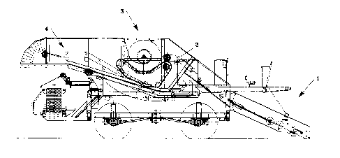
~ figure 1 schematically illustrates the side view of a tomato harvester in
accordance with the invention
~ figure 2 is an enlarged detail of figure 1, showing the devices that feed
the plants to the shaker
~ figure 3 is a view of a shaker with the plant feed devices
~ figures 4 and 5 illustrate a detail of a different form of embodiment of
the invention.
By reference to figure 1, a tomato harvester in accordance with the
invention is fitted at the front with a header assembly indicated as 1, which
cuts the plants and directs them onto a loading belt 2, which in turn
discharges them at shakers 3.
Here the tomatoes are separated from the plants; the tomatoes are
collected and automatically conveyed to fnal containers, while the plants
are discharged onto the ground by a belt 4. The structure of the harvester
is already known, and a detailed description of it is therefore not required
here.
In accordance with the invention (see figure 2), a feed belt 5 is fitted
immediately downstream of loading belt 2; feed belt 5 receives the plants
from belt 2 and conveys them to the shaker, follows the circular route
described by the ends of the shaker rods for a certain distance, and then
discharges the plants onto ejector belt 4.
Feed belt 5 basically consists of a conveyor belt with wide mesh 6, fitted to


CA 02307543 2000-OS-04
-4-
a drive roller 7 and a number of guide rollers and stop rollers 8.
A set of supports or arms 10 are fitted to rods 9 (see figure 3) which
constitute the structure of feed belt 5; the said supports project from the
belt, and a ring or the like 11 is fitted to their upper end.
Arms 10 are fitted to rods 9 in such a way that they are staggered in
relation to shaker rods 19.
A number of hoses 12 are fitted to belt 6; the said hoses are inserted
through rings 11 and therefore follow the route of belt 5, but remain at a
distance from belt 5 equal to the height of arms 10.
Loading belt 2 is fitted with several rows of fingers 13 which project
outwards and engage the cut plants to prevent them from sliding
backwards along the inclined belt when they are loaded into the harvester.
A roller 14, which turns in the immediate vicinity of feed belt 5, is fitted
to
the top end of loading belt 2.
In this way, arms 10 with rings 11 and hoses 12 are inserted between
fingers 14 of the loading belt, thus preventing some of the plants from
being dragged backwards by belt 2 when its route is reversed.
During the operation of the harvester the plants are cut by the header and
fall onto loading belt 2, which raises them and directs them into the
harvester. There, at the exit from belt 2, the plants fall onto feed belt 5
which conveys them to the shakers.
In this part of the route the plants are kept raised above belt 5, resting on
hoses 11 which follow the route of the belt; the set of hoses constitutes a
kind of grid which follows the route of the feed belt and keeps the plants
raised above it.


CA 02307543 2000-OS-04
-5-
In this section of the route the plants are subjected to energetic action by
the shakers which causes the tomatoes to be detached from the plants
and fall through the mesh of the belt onto the collector systems below. At
the exit from the shaking area, the plants are discharged from belt 5 onto
belt 4 which moves at a faster speed, with the result that the plants are
immediately carried away from belt 5 with no risk of their returning to the
processing cycle.
Various forms of embodiment are possible in the ambit of the same
concept. For example, arms 10 with hoses 12 could be replaced by a set
of rigid supports such as metal bars bent into an arch shape, semicircular
plates or the like, integral with rods 9, as shown in figures 4 and 5 and
indicated by number 20.
An expert in the field could devise numerous modifications and variations,
all of which should be deemed to fall within the scope of this invention.

Representative Drawing
A single figure which represents the drawing illustrating the invention.
Administrative Status

For a clearer understanding of the status of the application/patent presented on this page, the site Disclaimer , as well as the definitions for Patent , Administrative Status , Maintenance Fee  and Payment History  should be consulted.

Administrative Status

Title Date
Forecasted Issue Date Unavailable
(22) Filed 2000-05-04
(41) Open to Public Inspection 2001-11-04
Examination Requested 2005-03-14
Dead Application 2008-08-05

Abandonment History

Abandonment Date Reason Reinstatement Date
2007-08-06 R30(2) - Failure to Respond
2008-05-05 FAILURE TO PAY APPLICATION MAINTENANCE FEE

Payment History

Fee Type Anniversary Year Due Date Amount Paid Paid Date
Registration of a document - section 124 $100.00 2000-05-04
Application Fee $300.00 2000-05-04
Maintenance Fee - Application - New Act 2 2002-05-06 $100.00 2002-03-04
Maintenance Fee - Application - New Act 3 2003-05-05 $100.00 2003-02-03
Maintenance Fee - Application - New Act 4 2004-05-04 $100.00 2004-02-10
Request for Examination $800.00 2005-03-14
Maintenance Fee - Application - New Act 5 2005-05-04 $200.00 2005-03-24
Maintenance Fee - Application - New Act 6 2006-05-04 $200.00 2006-04-04
Maintenance Fee - Application - New Act 7 2007-05-04 $200.00 2007-02-02
Owners on Record

Note: Records showing the ownership history in alphabetical order.

Current Owners on Record
FMC TECHNOLOGIES ITALIA S.P.A.
Past Owners on Record
FMC ITALIA S.P.A.
SANDEI, LUIGI
Past Owners that do not appear in the "Owners on Record" listing will appear in other documentation within the application.
Documents

To view selected files, please enter reCAPTCHA code :


To view images, click a link in the Document Description column. To download the documents, select one or more checkboxes in the first column and then click the "Download Selected in PDF format (Zip Archive)" or the "Download Selected as Single PDF" button.

List of published and non-published patent-specific documents on the CPD .

If you have any difficulty accessing content, you can call the Client Service Centre at 1-866-997-1936 or send them an e-mail at CIPO Client Service Centre.


Document
Description 
Date
(yyyy-mm-dd) 
Number of pages   Size of Image (KB) 
Abstract 2000-05-04 1 24
Description 2000-05-04 5 183
Representative Drawing 2001-11-02 1 18
Cover Page 2001-11-02 1 50
Claims 2000-05-04 3 98
Drawings 2000-05-04 3 84
Assignment 2003-09-02 11 534
Assignment 2000-05-04 4 123
Fees 2003-02-03 1 30
Fees 2002-03-04 1 30
Fees 2004-02-10 1 29
Prosecution-Amendment 2005-03-14 1 26
Fees 2005-03-24 1 28
Fees 2006-04-04 1 34
Prosecution-Amendment 2007-02-05 2 49
Fees 2007-02-02 1 43