Note: Descriptions are shown in the official language in which they were submitted.
CA 02307916 2000-02-11
AMENDED PAGE.
Eu 97 586 PCT
Shaped Bodies
The invention relates to shaped bodies, which can, be employed in many
technical
fields. They may, for example, be used in backrests of seat furniture, in
order to
permit, for example, the individual adaptation of the backrest curvature to
the
persons sitting on the furniture at that time.
From DE 33 24 655 A1 a seat including a lumbar support is known, comprising an
adjustable spring rnetai sheet acting on the back rest upholstery, having
different
deformation rigidities in the upper and lower region.
From WO 94/08492 an adjustable back support including a panel is known,
adjustable by means of an upper and a lower tensioning element, adapted to be
adjusted individually.
The shaped bodies can.also be used in building for supports of differently
shaped
building components, during assemblies serving as supports for securing
packagings, for the prevention of damage to goods, in the medico-technical
field,
e.g. for couches, orthopaedic shoes etc. and in all fields, where certain
space
configurations should be capable of being modified for optical, technical,
medical
reasons, e.g. also adaptable supports.
It is an object of the invention to provide three-dimensionally shaped bodies
with an
integrated convexity, which are able to adopt in a simple and easy manner
different
space configurations, deviating from the original shape andlor which are
adaptable
to afford also, e.g., adequate support functions.
This object is attained by a shaped body, comprising at least one shaped body
(1),
whose unloaded three-dimensional inherent volume configuration includes at
least
one one-sided integrated convexity, displaceable by means of at least one
flexible
active element (5) connected along the convexity with the shaped body (1), by
way
of applying a variable compressive and/or tensile force onto the flexible
active
/"'_
~~~~Ur~l~ ~l~hi',
CA 02307916 2000-02-11
2
element (5) and/or wholly or partly convertible into a different three-
dimensional
volume configuration by means displacement into itself.
Advantageous embodiments of the invention are apparent from the subsidiary
claims.
The invention permits that a shaped body, the unloaded three-dimensional
inherent
configuration of which comprises at least one integrated convexity, e.g. any
desired
triangular cross-sectional shape, can convert wholly or partly into a shaped
body
with a different inherent configuration by applying force, in which case this
applied
force and as a result the spatial transformation can take place continuously
or
incrementally. Maximum ~ deformation is attained by maximum permissible force
application; when reducing the force application the deformation is reduced
until the
original inherent shape is attained again when completely unloaded.
For example, a wire, ribbon, cord, belt or a strip of plaited synthetic or
natural fibres
or even metal threads, a round or profiled rod of plastics or metal, a sheet
metal
strip or the like may be used as the active element, in which context merely
an
adequately flexible resilience and resistance force sufficient for the forces
to be
applied must be present, at least in the direction of attack and transmission
of a
force. It is also possible to provide e.g. a tensile or pressure element in
the direction
of tension or pressure with different elasticities, e.g. by using spring
elements, for
example for damping and/or to subdivide it, in which case any suitable device
may
be inGuded between the parts for applying forces to the active elements.
The shape-variable shaped body, may e.g. be a spatial tiody, consisting of one
or
more parts, suitable to absorb suppor5ng forces on the one hand and to
transmit
these to the active elements or vice versa. It may be made of plastics, in
particular
foam plastics, it may take the form of a cushion body and may also include non-
deformabie parts. The shaped body may be composed of individual elements,
which
in tum form shaped bodies, which individually or in a flexible envelope is
possible; the latter may even be elastic. The deformable parts of the shaped
body
may also be provided on top of or on a non-deformable part, e.g. a core of
wood,
CA 02307916 2000-02-11
WO 99/08570 3 PCTIEP98105157
metal or plastics or they may be composed of a plurality of rigid parts
movable in
relation to one another. Rests, seats, couches, optical and other advertising
means,
stage sets, camouflage devices, tools, tool apparatus, support structures and
all
types of frames, a mattress part, a bed frame, a packing container or a
container,
shoes and many more may, for example, serves as support means or carrier. A
shaped body may likewise be composed of individual rigid segments, which are
connected loosely next to one another or in an articulate manner to an active
element, a support, holding means or the like. The latter may consist of one
part, it
may e.g. be made of plastics.
Any device, capable of exerting force on the shaped bodylbodies by way of the
active element, may serve for the modification of the forces to be applied, in
which
case the active elements may in the process be both stressed and unstressed.
An
arrangement permitting the application of pressure onto the shaped body/bodies
is
likewise possible. The device may be driven mechanically or by a motor and may
be
operated directly or by remote control, e. g. by means of a Bowden cable or
rods or
even pneumatically, hydraulically, electrically or by wireless means.
The connection between the shaped bodies and the active elements) may be
effected in any desired way, e.g. by adhesives, welding, riveting etc., in
individual
cases also by mere friction, e.g. if the shaped body is arranged in a closed
envelope.
In what follows the invention will be elucidated in more detail according to
and by
way of working examples. There is shown in
Fig. 1 an embodiment of a shape-variable shaped body in three positions in a
diagrammatic view;
Fig. 2 a section of a backrest with a shape-variable shaped bpdy in cross-
section;
Fig. 3 a different backrest with a shape-variable shaped body in cross-
section;
Fig. 4 two further embodiments of backrests as a fitted module and as a loose
cushion in cross-section;
msusecslmarinavtrlesze112000.doc
CA 02307916 2000-02-11 ..
WO 99108370 4 PCT/EP98/05157
Fig. 5 a shoe with a shape-variable shaped body in cross-section;
Fig. 6 a mattress with two shape-variable shaped bodies in cross-section;
Fig. 7 a bed with three shape-variable shaped bodies in cross-section;
Fig. 8 a longitudinal section (A) and two cross-sections (8, C) of a seat
backrest
including a shaped body extending in longitudinal, vertical and transverse
direction, on which the active elements engage in vertical as well as in
transverse direction;
Fig. 9 a transport container including two variable shaped bodies arranged
therein
for stabilising a great variety of transport goods;
Fig. 10 a shape body, whereon at two staggered localities active elements
attack in
order to displace and change the shape and the vertex;
Fig. 11 a shaped body, adapted to stretch in longitudinal direction and rigid
and
pressure-resistant in transverse direction;
Fig. 12 a shaped body including spaced apart segments, the body configuration
and
volume of which is variable;
Fig. 13 a second embodiment of a shaped body comprising spaced apart segments;
Fig. 14 a third embodiment of a shaped body comprising spaced apart segments,
the body configuration and volume of which are variable; .
Fig. 15 a shaped body comprising segments, arranged one against the other in a
sleeve;
Fig. 16 shaped body comprising segments arranged in a fishbone-like pattern,
the
body configuration and volume of which are variable;
a~~~rt~~zeu2ooo.ao~
CA 02307916 2000-02-11
WO 99108570 5 PCTIEP98J05157
Fig. 17 a fourth embodiment of a shaped body comprising spaced apart segments,
the body configuration and volume of which are variable;
Fig. 18 a fifth embodiment of a shaped body comprising spaced apart segments,
the
body configuration and volume of which are variable.
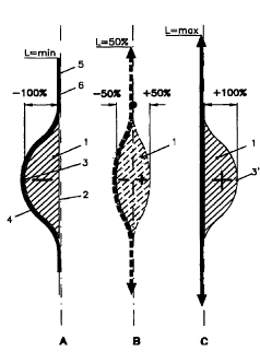
In Figure 1 a basic concept of the invention is shown by way of a shape-
variable
shaped body 1 in three different shapes. The shaped body 1 is shown in Fig. 1A
in
its position of rest, i.e. in its inherent configuration, consisting in the
embodiment of
a level base 2 and a convexity 3, designed in crass-section in the embodiment
symmetrically as a rounded isosceles triangle, but which may also be
asymmetrical.
Along the convexity 3 an active element 5 of optional type, e.g. in the form
of a
flexible tensile strip 6, is fitted by a connecting means 4, which may, for
example be
a resilient adhesive. The shape-variable and resilient shaped body 1 is
designed
slightly stretchable in longitudinal direction ( from top to bottom in Fig. 1
A), whereas
it is nearly pressure resistant in transverse direction. If a tensile force is
applied to
the tensile strip 6 on one end, the other end behind the shaped body 1 then
being
fixed in position, or if a tensile force is applied to both ends (see arrows
in Fig. 1 B),
the tensile strip 6 begins to stretch, pressing the shaped body 1 forward,
elastically
deforming it, until it reaches the final position shown in Fig. 1 C, in which
the shaped
body 1 has a mirror image configuration in relation to the original position,
i.e. the
convexity 3' then faces the side opposite the original position. If the
tensile forces
are slowly or spontaneously reduced and ultimately cancelled, the shaped body
1
returns from the configuration shown in Fig. 1C to that shown in Fig. 1A under
its
inherent tension/inherent resilience. By adjusting the tensile force from zero
to a
value, at which the tensile strip 6 is completely stretched,' any desired
position, i.e.
convexity of the shaped body 1 can be set between the two original positions.
The embodiment shown in Fig. 2 in two positions, shows a seat backrest with a
support structure 7, e.g. in the form of a shell, comprising a trough-shaped
concavity
8. Above the concavity 8 an active element 5 in the form of a tension belt 9
is fitted,
designed in such a manner as to be able to rest non-stressed in the concavity
8. In
the end region or underneath the concavity 8 a device 10 is fixed to the
shell, by
means of which forces are transmitted onto the tension belt 9. The device 10
may
for example be a coiling apparatus for a tension strip 6 or a tension belt 9
or even a
msusers~narinaurlelzel12000.doc
CA 02307916 2000-02-11 ....__ ....,.. _ ..
WO 99/08570 6 PCTIEP98/05157
rope or a cloth strip. Inside the shell a shaped body 1 in the form of a back
support
is provided, in which context the back support has a convexity 3,
corresponding in
its form to the concavity 8 or vice versa. In particular the parts of the back
support
without convexity, situated in the upper and lower portion outside the
concavity 8 of
the shell, may be releasably or permanently fitted. A releasable connection
can be
brought about e.g. by Velcro fasteners or by snap fasteners. A conceivable
fixation
of the tension belt 9 in the region of the convexity 3 is not required in the
present
case, as frictional contact exists with the shaped body 1. In the original
position
inherent to the back support, the convexity 3 abuts against the shell in the
concavity
8, just like the tension belt 9. Should an individual adaptation of the shaped
body 1,
serving as a lumbar support, to the concrete shape of the person using the
back
rest, be performed now; 'the tension belt 9 is coiled up by the device 10, in
the form
of a coiling device, causing it to become tensioned and assuming in the final
stage
the linearly stretched position shown in Fig. 2B. During coiling the convexity
3 is
moved continuously from the concavity 8 and is displaced outwardly until the
shaped body 1 in its final stage assumes the convexity 3', now directed
outwardly
as shown in Fig. 2B. If the tension belt 9 is uncoiled again by the coiling
device, the
convexity of the backrest returns again into the originally specified original
shape
and position due to its inherent resilience or the force of tensioning etc. By
means of
a locking device, not shown, or a self-locking tensioning. device coiling and,
as a
result, the tensile force applied to the tension belt 9, can be stopped in any
position,
so that the individual adaptation can be retained.
A simple embodiment, not illustrated, consists of a shaped body as described
in Fig.
1, the convexity of which is connected to a web, e. g of fabric, serving as
the active
element. The upper free end of the web of fabric is fixed, e.g. on a cross
beam
while a coiling device is fixed in its position underneath the shaped body, by
means
of which coiling and uncoiling of the fabric web and thus its tensioning and,
as a
result, also the modification of shape of the shaped body becomes possible.
The back including the head rest shown in Fig. 3 consists of a support
structure T in
the form of a rigid foam back part, on which a head rest is provided in the ~
upper
region, comprising a cavity 11, serving inter olio for the accommodation of
the
shape-variable shaped body 1. In this case the device .10 for the application
of
forces is self-locking and connected to a Bowden cable arrangement 12, in
which
mwserslmarinalule~ze112000.doc
CA 02307916 2000-02-11
WO 99108570 7 PCT/EP98/05157
context a portion of the cable arrangement 13 is connected to the convexity 3
of the
shaped body 1. The cable arrangement 13 is guided around two deflecting points
14, 14'. The Bowden cable arrangement 12 may be provided with any device 10
for
applying forces, in the present case for shortening and lengthening the cable
arrangement 13, by which the desired deformation of the shaped body 1 is
brought
about, as described above. On that side against which the user is leaning, a
flexible
cover 15 covering the cavity 11 and the shaped body 1 is provided on the
sturdy
back part, which may likewise serve as upholstery or for absorption and which
abuts
loosely against the shaped body 1 or may also be connected to the latter.
A further modification of the embodiment resides in that either at the upper
or the
lower end or even at both ends the tension strips or belts are deflected at
the
holding means and are passed to the rear side. Because of the two deflection
points 14, 14' it is possible to arrange the device 10 for applying the active
forces in
the rearward, i.e. hidden, region. Preferably, the friction, increased by the
deflection, may be reduced by suitable measures, such as for example rolling
bodies provided on axles. If, as shown in Fig. 3, deflection takes place at
the top
and at the bottom, it is also possible, while adhering to the modified shape
of the
shaped body 1, set in each particular case, to move the latter up and down.
This
may be done, for example, in that one of the deflection points 14 or 14' is
designed
for the cable arrangement 13 as a rotary bearing (not shown), e.g. by using a
rotatable bush, around which the cable arrangement 13 is guided, optionally
with a
complete wrap. By turning the bush, optionally by means of suitable
expedients, the
up and down adjustment of the shaped body 1 can be performed, in the course of
which the device 10 for the application of forces must not impair this
movement. The
device 10 for the application of forces may itself be designed to move up and
down,
so that by its up and down movement the level adjustment can be performed in
each particular case. .
Fig. 4 shows two embodiments of a backrest. The embodiment shown in Fig. 4A
represents an independent module, which can, for example, be locked, e.g.
hinged,
as a whole in a seat frame without any tool. The embodiment illustrated in
Fig. 48 is
designed as a mobile, transportable backrest. The shaped body 1 of the
backrests
correspond with regard to configuration and function to the above described
shaped
bodies, so that in the following deviations only will be pointed out. In both
examples
~~rswle~u2ooo.ao~
CA 02307916 2000-02-11
WO 99/08570 $ PCT/EP98105157
an active element 5 in the form of a tensile element 6 is likewise provided,
fitted to
the upper end of an upper end piece 16 (Fig. 4A), which takes the form of a
hook in
the present example. The hook-shaped end piece 16 is adapted to be hooked, for
example, to a transverse rod 17, forming part, for example, of a seat frame
(support
structure 7). The lower end of the tensile element 6 communicates with the
device
for applying forces, which may be designed as a coiling device including an
eccentric means. By means of an eccentric means the adjustment characteristics
may be modified, e.g. first rapidly with little force and then slowly with
increasing
force. The hook-shaped end piece 16 may be connected to a back panel T or may
form an integral part of it. At the lower end of the back panel T or on the
seat frame,
respectively, hooks 18, clamps, eyelets or the like are provided by means of
which
the module can be fitted to the seat frame, preferably without any tools. The
module
may have any desired support structure, even without a back panel.
In the embodiment shown in Fig. 4B a closed, but in any event U-shaped frame
19
with a back panel T and a base 20, e.g. a skid or the like is provided. The
frame 19
may also be designed as a shell, into which a concavity 8 is integrated. At
the upper
end the active element 5, e.g. a fabric web, is fitted to a support rod 21,
adapted to
be inserted into a tube 22 having a gap 23 in order to introduce 'the fabric
web into
the frame 19. The active element 5 may also be composed of a plurality of
tension
belts, arranged side-by-side, in which context their attachment, e.g. to a
coiling
device may be effected on axle journals having different outer diameters, so
that
during rotation of the jointly shared axle the tension belts can be rolled up
at
different speed, which also permits exercising a certain effect in transverse
direction
on the shaped bodies 1, e.g. lateral support. It is also possible to provide a
plurality
of coiling devices, which can be activated individually or by any desired
interconnection. Active elements can, of course, also attack in transverse
direction,
in order to act on the backrest cross-section.
It stands to reason that in all described embodiments the device 10 for
applying
forces, such as e. g. coiling or tensioning devices, may also be arranged at
the
upper end of the backrest and that actuation may also be performed from a
distance, e.g. by a Bowden cable arrangement. A motor-driven means, driven
electrically, hydraulically or pneumatically can also be employed. By making
use of
endless screws, threads, eccentric means etc., the coiling or tensioning
device may
rt~susecsunarina~trlo~zett2ooo.doc
CA 02307916 2000-02-11
WO 99108570 9 PCTIEP98105157
also have self-locking properties, which automatically ensure locking in any
desired
position by an adjustment by means of a handwheel or a lever, without having
to
employ locking means, which have to be actuated specifically, or releasable
latching
devices.
Fig. 5 shows a shoe including an orthopaedic support by means of a shape-
variable
shaped body 1. In this case the adjustment of the active element 5, e.g. in
the form
of a tensioning cord 24, may be performed by a reeling device 25 (Fig. 58),
adapted
to be shifted and locked or by a Bowden cable arrangement including a screw
spindle 26. The shaped body 1 is covered by a flexible shoe sole 27.
Fig. 6 shows a mattress,' comprising two shape-variable shaped bodies 1 and 1'
in
longitudinal direction, one in the head region and one in the lumbar region.
In this
case frame elements are provided, to which the active elements 5 andlor the
devices 10 for applying forces can be fitted, in which context deflections and
supports may be provided, if required. The mattress further comprises a body,
e.g. a
foam body, in which concavities 8, 8' and/or gaps for the shaped bodies 1 and
1'
are provided, as well as a closed cover 15.
Fig. 7 shows an application of the invention within a bed frame, where three
shape-
variable shaped bodies 1, 1', 1" are provided in longitudinal direction,
permitting an
action similar to that of a slatted bed frame.
Fig. 8 shows a vertical section through the back of a seat (Fig. SA), in which
a
shaped body 1 is illustrated, adapted to vary its shape in vertical and
transverse
direction, associated further with transversely directed active elements 5 in
the form
of tension strips 6, 6", in order to attain a deformation also over the cross-
section
(see Fig. 8B and C), in which case it is also possible to provide merely one
active
element or further such active elements in transverse direction.
Fig. 9 shows a cross-section through a packaging container 28 including two
boomerang-shaped, shape-variable shaped bodies 1, 1', the wings of which abut
in
each case against the adjacent walls of the packaging container 28 (inherent
shape). On the surfaces of the shaped bodies 1, 1' bearing against the walls,
tension belts 6, 6' are provided to serve as active elements 5, fitted to one
end,
a~~wle~eu2ooo.a~
CA 02307916 2000-02-11
WO 99108570 1 ~ PCT/EP98/05157
close to one of the comers 29, 29' (Fig. 9A) of the packaging container 28, in
which
the two shaped bodies 1 and 1' meet, and inserted at the other end into a self-
locking tensioning or coiling device serving as the device 10 for applying
forces. In
one or both shaped bodies 1, 1' incisions 30 andlor wedge-like openings may be
provided, permitting better adaptation of the variable shaped bodies 1, 1' to
the
prevailing shapes of transport goods 31 or even facilitating a modification of
shape.
In Fig. 9B transport protection is shown on three different goods 31 by means
of the
shape-variable shaped bodies 1, 1'. It stands to reason that for specific
purposes
the use of only one or a larger number of shaped bodies 1 is possible for a
packaging container 28 of any desired shape. The original shape as well of the
variable shaped bodies 1, 1' may be adapted in advance to any desired goods 31
to
be packed. '
For the majority of embodiments described up to now the modification of a pre-
determined variable shaped body takes place only until it reaches its negative
or
mirror image shape, i.e. the deformation is virtually a displacement in
itself.
Examples will still be set. out hereafter, where an additional modification or
additional modifications is/are provided by superimposed force application(s).
Fig. 10 shows the influence of forces at two spaced apart locations 32 and 33
on
the active element 5, connected to a shaped body 1, permitting in the
embodiment a
vertex displacement of a convexity 3 from S1 to S2 and back, depending on the
predetermined original shape, in which case at the two spaced apart locations
32
and 33 tensile forces of any desired combination, as the case may be, even
compressive forces, may be applied onto or reduced from~the active element 5
with
varying intensity. This causes a broad variation of the modification of the
shaped
body 1, which can be further modified by modifying the position andlor the
number
of the points of engagement 32, 33. It is also possible to provide further
active
elements 5, which permit the transmission of forces in any further direction,
so that
the shaped body 1 can be subjected to further deformations, in which case
further
main and side effects, such as e.g. vibration and/or massage movements, can be
attained.
Fig. 11 shows a shaped body 34 in the form of a resilient body, stretchable in
longitudinal direction, consisting in transverse direction of rigid,
approximately
m~~rsurl~~uu2ooo.do~
CA 02307916 2000-02-11
~°,
WO 99108570 1 1 PCT/EP98/05157
parallel folds with an increasing and then decreasing fold height, i.e. in its
original
shape it has a linear base 2 and a convexity 3. In the embodiment shown, the
active
element 5, a tension strip 6, associated with the shaped body 34 is guided
around
two deflection points 14, 14', the two ends 6a and 6b of the tension strip 6
{see Fig.
11C and D) being interconnected by means of a device 35, adjusting the spacing
of
the ends 6a and 6b from one another. In addition, one of the deflection points
14 or
14' is arranged in a distance-adjustable manner in relation to the other. If
the two
deflection points 14, 14', as shown in Fig. 11A, are positioned as closely
together as
possible, the tension strip 6 is unstressed and the shaped body 34 is present
in its
predetermined original state. In this case the respective terminal fold may be
anchored on the active element 5. By varying the spacing in the sense of
moving
the deflection points 14; v14' away from one another, e.g. by shifting the
axis of a
deflection roll forming the deflection point, the active element 5 expands and
stretches the shaped body 34, displacing it at the same time. The displacement
may
be effected additionally or also solely in that, as described above, the
spacing
between the strip ends 6a and 6b is adjusted. Two possible modifications are
illustrated in Fig. 11 C and Fig. 11 D, both comprising an adjustment
mechanism
including a Bowden cable arrangement. If one of the two deflection rolls is
turned
about its own axis, a displacement of the vertex of the opposite convexity 3'
is
caused.
Fig. 12 illustrates a further modification of a device for modifying a shaped
body and
for the additional displaceability of the vertex of the displaced convexity 3'
of a
shaped body 36. In this case the shaped body 36 is composed of segments 37,
fitted to any desired flexible support 38 in an articulate manner in spaced
apart
relationship, their other ends being likewise fitted in an articulate manner
to a
flexible active element 5. In this case the segments 37 are disposed at an
angle in
relation to the horizontal line. In the embodiment shown, the heights of the
individual
segments 37 in relation to the horizontal line are so selected that their
vertexes
describe a curve, i.e. a convexity 3. If the active element 5 is fitted to one
end and if
tension is applied on the other end until it is completely stretched, then not
only a
convexity 3' is attained in the opposite direction, but also a vertex
displacement,
depending on the angle setting and the displacement of the active element 5
from
the concavity 8 into the stretched position (see Fig. 12B). If the setting of
the fixing
msusers~marinaltrle~ze112000.doc
CA 02307916 2000-02-11
CVO 99/08570 12 PCTlEP98105157
point and the direction of tension are changed on the active element 5, a
vertex
displacement takes place in the opposite direction (see Fig. 12C).
The embodiment illustrated in Fig. 13 shows a structure, similar to the one
described in Fig. 12; in this case, however, a shaped body 39 is provided, in
which,
symmetrically to the central line the individual segments 3T of the right
side, as
opposed to those of the left side, are disposed symmetrically but at opposed
angles
to the horizontal line and are connected in an articulate manner to the active
element 5 or the support 38. A uniform convexity is attained in that from both
ends
an even tension is applied to the active element 5. If the tension is applied
unevenly
from both ends, a displacement of the vertex can again be brought about within
certain limits. '
In the embodiment illustrated in Fig. 14 the shaped body~39' has the
configuration
described in Fig. 13. In this case, however, the active element 5 is fixed to
both
ends and is separated in the centre between the two segments 3T having an
opposed angle arrangement and provided with a device 35' for the adjustment of
the spacing between the separated ends. If the ends touch, i.e: if the spacing
becomes zero, the curved position of the shaped body 39 is attained, as shown
in
Fig..14B.
Fig. 15 shows an embodiment of a shaped body 40, composed of individual
segments 37", which, freely movable in relation to one another, but deriving
support
from one another, form a shaped body 40 having a downwardly directed convexity
3. Underneath the shaped body 40 an active element 5 is provided in a
concavity 8,
corresponding to the convexity 3 while a flexible cover 15 is disposed above
the
shaped body 40. In this embodiment, forming an enclosed shaped body 40, due to
the cover 15 and the active element 5, no connection is required, neither to
the
active element 5 nor to the cover 15, since the individual segments 37" are
disposed
side-by-side, supporting one another and are held from below by the active
element
5. In this embodiment, the tensile farce is preferably applied to both ends.
In Fig.
15B a convexity element 40 modified by stretching of the active element 5 is
shown,
the new convexity 3' of which points into the direction opposite the original
position.
a~~w~~emooo.a~
CA 02307916 2000-02-11
WO 99/08570 13 PCT/EP98105157
Fig. 16 shows an embodiment of a shaped body 41, in which the individual
segments 37"' are arranged in a fishbone-like pattern, the active element 5
being
disposed in each case connected to them in an articulate manner between the
upper and the lower segments 37"', where applicable even with a longitudinal
slip.
The free ends of the segments 37"' are mounted in an articulate manner in a
flexible envelope 42, sun-ounding the shaped body 41. If a force is applied to
the
active element 5, rigidly connected in an articulate manner at one end to the
last
pair of segments with a slip, the shaped body 41, which in its original
position, see
Fig. 16A and C, is extremely flat, can be converted into a balloon-shaped
body, see
Fig. 16 B and D. Provided there is no concavity or gap and the shaped body 41
is
arranged on a surface, e.g. a level surface and a tensile force is applied to
one side,
the shaped body 41 out' of the original position shown in Fig. 16C experiences
a
maximum balloon-shaped deformation as illustrated in Fig. 16D. In this process
the
active element 5 no longer farms a straight line but a curve.
Figs. 17 and 18 show embodiments of a shape-variable shaped body 43,
functioning e.g. on a plane or even on curved surtaces of any design, i.e.
without a
real concavity being present, into which the shaped body can be introduced or
in
which it is originally disposed. Fig. 17 shows a plate 44, on which the shaped
body
43 is provided, composed of segments 37 of different height, fitted in an
articulate
manner to the plate 44 in spaced apart relationship, the free ends of which
are
connected to an active element 5 in an articulate manner, and on which, as the
case may be, a cover 15 may be provided. In the position~of rest shown in Fig.
17A
the shaped body 43 adopts its flattest shape, i.e. its starting position. With
the
application of a tensile force onto the active element 5 in the direction of
the arrow
according to Fig. 178 the segments 37 rise and the shaped body 43 becomes
curved. If the segments 37 are vertical in relation to the plate 44, the
convexity
attains the maximum vertex height. For the possible attainment of the vertex
height
a restoring force, e.g. in the form of a spring or shearing force, must be
provided for
pivoting the segments 37.
The embodiment of a shaped body 45 illustrated in Fig. 18 is structured in a
way
similar to the one described in Fig. 17. In this case the segments 37 are
fitted in an
articulate manner in spaced apart relationship on a preferably rigid active
means 50
serving as the active element 5 instead of directly on the plate 44 as in the
~~~~~emooo.ao~
CA 02307916 2000-02-11 -
WO 99/08570 14 PCT/EP98/05157
embodiment according to Fig. 17. In the present case the plate 44 serves as a
support and/or guide means for the active element 5, e.g. a tension rod 46.
The free
ends of the segments 37 are in the present case fitted to a cover 15 in an
articulate
manner. If a tensile force is applied in the direction of the arrow in Fig.
20B, the
segments 37 are raised and a curved shaped body comes about according to their
longitudinal dimensions and their disposition. In the event of the use of a
dimensionally rigid active element 5, a reduction of the convexity can again
be
attained, in the case of further movement of the active element 5, up to a
position,
where the segments 37 are once again lying side-by-side, however in a
direction
opposite to the position shown in Fig. 18A. If the cover 15 has an inherent
elasticity,
i.e. is able to apply a force on the segments 37, the active element 5 may
also
consist of any flexible, tension-resistant material, as the return of the
segments 37
into the starting position can then be effected by the resilience and the
tension force
of~the cover 15, provided possible self-locking is excluded by appropriate
measures.
By means of the embodiments shown in Figs. 16 to 18, the deformation of a
shaped
body can be performed, enlarging its volume.
The individual components described as well as functionally similar components
may be utilised in any desired combination for the manufacture of shaped
bodies,
just as the described individual shaped bodies may likewise be combined into
units
in any desired way.
mausecstmarina~le~ze112000.doc