Note: Descriptions are shown in the official language in which they were submitted.
CA 02308213 2000-04-20
WO 99/Z1122 PCT/US98/22392
VOICE-OUTPUT READING SYSTEM WITH GESTURE-BASED NAVIGATION
Cross-Reference To Related Patent Applications
This application is related to and claims priority from United States
Provisional Patent Application No.
60/063,135. filed October 22. 1997. titled "Voice-Output Reading System with
Gesture-Based Navigation;' and
from United States Provisional Patent Application No. 601068.713. filed
December 29, 1997. titled "Voice-Output
Reading System with Gesture-Based Navigation," the contents of each which are
incorporated herein by reference.
Technical Field
The present invention relates to an electronic reading system for converting
text to synthesized speech that
may be used by low-vision and blind people. as well as others that have
difficulty reading printed text. and more
particularly relates to an electronic reading system that includes improved
functionality for allowing the user to
navigate within the text.
Background Art
Our daily lives are filled with the need for reading printed material at any
time and in any place. Utility
I i bills and mail at home. food labels at the supermarket. clothes labels at
the department store. textbooks at school,
manuals and reports at work. and menus at restaurants are but a few examples.
Nearly 10 million people in the
United States have visual impairments which prevent them from reading books or
the newspaper, even with the
assistance of reading glasses. contacts or ma~nitiers, and millions more have
mental and learning disabilities that
severely limit their reading. To these people. their inability to read these
materials in the places they are
'_0 encountered puts them at a severe disadvantage.
Electronic reading machines using computer-based optical character recognition
(OCR) have been used
since the late 1980's to assist these reading-impaired people. in general,
electronic reading machines have
comprised personal computers outtitted with computer scanners. optical
character recognition software, and
computerized text-to-voice hardware or software. Currently, machines are sold
by a variety of companies,
?5 including Telesensotw of Mountain View. California. Arkenstone of
Sunnyvale. California. and Kurzweil
Educational Systems of Waltham. Massachusetts. In general, the operation of
these systems involves placing text
on a scanner and obtaining a pixel bitmap of the page to be read. converting
that image to text using an OCR
program in the personal computer to which the scanner is attached. and
generating speech output of the interpreted
text using a text-to-speech software program. In order to navigate through the
text on the page, the user either
30 presses keys on the computer keyboard or keys on a special keypad in order
to skip forward or backward by word.
sentence or paragraph. repeat a section. or otherwise move through the
formatted text.
These reading machine systems, unfortunately. suffer from a variety of
operational insufficiencies that limit
their effectiveness. For instance. before the reading machine can begin to
read a page, the user must typically wait
CA 02308213 2000-04-20
WO 99/21122 PCT/US98/22392
over a minute. This delay is due primarily to three causes. Firstly, scanning
a page is a mechanical action that
takes time to move the electro-optical components over the page. Secondly, the
large amounts of information in
the scanned image require time to be transmitted to the computer. Thirdly,
optical character recognition of an
entire page can take considerable time. Thus, if a user wanted to scan through
a newspaper or a magazine,
considerable time would be needed simply to wait for the each page or scanned
sections of text to process to the
extent that it could begin audibly reading the text.
Another insufficiency of conventional reading machines is that scanners are
limited in the size of page they
can process. and reading a newspaper page would require multiple passes
through the scanner. Furthermore, the
keypad navigation of current reading machines requires that the user move
through the text in the same order in
which the computer organizes the data. At best. the user can skip over some
paragraphs quickly, but the way in
which the user is forced to apprehend the data is in the same linear fashion
that the computer stores the
information. This difficulty is less important in most books, in which the
information is largely along a single
narrative track, but can be quite limiting with highly formatted text such as
newspapers, magazines, scientific
journals, bus schedules. utility bills, and advertisements.
The majority of vision-impaired individuals have some residual vision, and
many of these people use
electronic magnifiers instead of OCR-based electronic reading machines. These
magnifying systems generally
consist of an electronic video capture system (usually with a CCD camera)
connected to a video display. The book
to be read is placed on a mechanical tracking mechanism beneath the video
capture system. and assists the user in
moving the book horizontally so as to keep the current line of text within the
field of view of the camera. Means
are generally provided to the user to adjust the contrast of the image, invert
the colors of the image, and adjust the
focus through manual controls on the face of the magnifying systems.
Because people with residual vision feel empowered using their remaining
vision, and because they can use
the magnifying systems to see information that is outside the scope of reading
machines (e.g. seeing graphics on a
page), and because they are generally less expensive than electronic reading
machines, magnifying systems
?5 currently enjoy a far larger market than electronic reading machines. The
are a large number of such magnifying
systems currently available, including ones from Telesensory of Mountain View,
CA, Magnisight of Colorado
Springs, CO. and Opteiec of Westford, MA. However, conventional magnifying
systems suffer from a number of
problems.
For example, the mechanisms for tracking lines of text are often difficult to
use, since they are manually-
guided mechanical systems that require relatively precise and steady hand
movements to guide the movement.
This requirement is difficult for certain people, especially the elderly who
have fine motor problems, but also
because it involves cognitive feedback control at the same time that
considerable effort is being devoted to
interpreting the images on the screen. Furthermore, when short columns of text
are being read, the user must
engage in frequent control of both vertical and horizontal mechanical guiding
systems. Also, because of the small
field of view of the camera and the limited movement of the mechanical system,
the page must often be re-
positioned on the mechanical guides. Because of the small field of view of
these systems, it is difficult for the user
to understand the overall structure of text and graphics on a complexly
formatted page. In addition. the system
depends entirely on the user's vision, even though this vision may be adequate
only for very slow reading. Yet
furthermore. the image manipulations afforded by these systems (e.g. contrast,
brightness, zoom and focus) are
-2-
CA 02308213 2000-04-20
WO 99/21122 PCTNS98/22392
generally limited. since they depend on mechanical systems and analog
electronics. rather than the much greater
range of possible effects of a digital system.
It was our intention to solve the problems of the prior art, both with regards
to OCR-based electronic
reading machines as well as electronic magnifying systems, that gave rise to
the current invention.
Summary of the Invention
It is an object of this invention to provide a system to permit users to
designate text to be read and to
specify control system parameters through manual gestures.
It is also an object of the present invention to provide a system with both
magnification and reading
capabilities.
It is in addition an object of the present invention to provide a system that
is affordable.
It is another object of the present invention to provide a system that allows
a user to easily and rapidly
select for reading text sequences that are distributed across widely separated
regions of the current page.
It is additionally an object of the present invention to provide a system that
allows a user to read from
highly formatted pages of text.
It is still another object of the present invention to provide a system that
reads text very shortly after the text
is placed in the view of the system.
It is further an object of the present invention to provide a system that can
be easily used from a seated
position.
It is also an object of the present invention to provide a system that allows
a user to read text from a large
page. such as that a newspaper.
It is still further an object of the present invention to provide a system
that is easy to learn to operate.
It is vet another object of the present invention to provide a system that can
be used by people with
difficulties in fine motor control.
It is additionally an object of the present invention to provide a system that
can read text printed in a wide
'_'~ variety of formats on a wide variety of substrates. including medicine
bottles. food packaging. and informative
siens, as well as paper.
It is a yet further object of the invention to provide a device that can have
many applications in daily life.
including enabling reading-disabled people to read. helping children learn to
read, and as a data input device for
home and office.
Additional objects. advantages and novel features of this invention shall be
set forth in part in the
description that follows. and will become apparent to those skilled in the art
upon examination of the following
specification or may be learned through the practice of the invention. The
objects and advantages of the invention
may be realized and attained by means of the instrumentalities. combinations.
and methods particularly pointed
out in the appended claims.
3s To achieve the foregoing and other objects and in accordance with the
purposes of the present invention, as
embodied and broadly described therein. the present invention is directed to a
method for electronically reading
text under interactive control by a user. The method includes obtaining a
digital image that includes text to be
read, performing symbology recognition on the digital image, determining a
command signal from a sequence of
- j -
CA 02308213 2000-04-20
WO 99/21122 PCT/US98/22392
user-generated spatial configurations of at least one pointer, choosing a
subset of the recognized svmbology to
read on the basis of the determined command signals, and converting the chosen
subset of recognized symbology
into a humanly perceptible version.
The present invention is also directed to an electronic reading apparatus for
convening text to spoken
words for a user. The apparatus includes a digital imaging device that
converts text to a digital imaging signal,
and a character recognizer receptive of the digital imaging signal, the
recognizer generating a recognized character
signal comprising the symbolic identity of the recognized text and the
location of the recognized text relative to
the digital imaging signal. The apparatus also includes a pointer that is
operated by the user to indicate
commands, wherein commands are encoded in the location and movement of the
pointer, and a pointer tracker
receptive of the pointer location and movement. the tracker generating a
pointer location and movement signal.
The apparatus further includes a command interpreter receptive of the pointer
location and movement signal and
the recognized character signal. the interpreter generating a command signal.
and a controller receptive of the
command signal and the recognized character signal. the controller generating
an output signal representative of at
least portions of the text recognized. In addition. the apparatus includes a
transducer receptive of the output signal
I ~ for converting the output signal to a humanly-perceptible form.
Brief Description of the Drawin>ss
Fig. la is a perspective view of a device incorporating the frst embodiment of
the present invention.
Fig. t b is a perspective view from below of the camera mount depicted in Fig.
la.
Fig. ? is a flow diagram of the steps of information processing of the device
of Fig. la.
Fib. 3 is a perspective view of a device incorporating the second embodiment
of the present invention.
Fig. :1 is a perspective view of a device incorporating the third embodiment
of the present invention.
Fig. ~a is a side view of a device incorporating the fourth embodiment of the
present invention.
Fi;. ~b is a side view of the device of Fi~~. ~a. with the fin2er in a
different configuration.
Fie. ~c is a front view of the device of Fi_. ~a.
'_'~ Fie. ~d is a side view of a variation of the device of Fig. aa, with a
cut-away view of the lens system.
Fig. 6 is a tlow diagram of the steps of pointer tracking. as used in the flow
diagram of Fig. 2.
Best Mode for CarrVInQ-Out the Invention
Overview ofthe First Preferred Embodiment
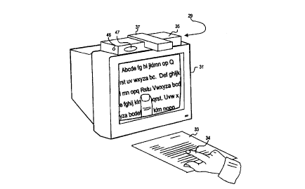
Fig. I a is a perspective diagram of the first preferred embodiment of the
present invention. The electronic
reading machine 29 is mounted on top of a video monitor 31 with the field of
view onto the surface below on
which printed material 33 is placed. The printed material 33 can be text in a
variety of formats on a variety of
substrates, including books. magazines. newspapers, food packaging, medicine
bottles, bus schedules. utility bills,
or CD-ROM labels. The electronic reading machine 29 comprises a main system
35, from which a camera mount
33 protrudes. The camera mount 37 comprises one or more electronic imaging
devices (such as CCD or CMOS
cameras).
-4-
CA 02308213 2000-04-20
WO 99/21122 PCT/US98/ZZ392
A view of the camera mount 37 from the underside is shown in Fig. lb. a
perspective diagram. A camera
39, which may comprise a CCD or CMOS imaging sensor 41 along with an attached
lens 43. is angled away from
the main system 35, so that it is directed towards the printed material 33.
Optionally, the camera mount 37 may incorporate one or more illumination
sources, so as to provide
constant illumination over the field of view. In Fig. 1 b. such illumination
is provided by two rows of illumination
sources 45 along the lateral edges of the mount 37. These illumination sources
45 may comprise rows of LEDs,
thin fluorescent sources I uch as T1 lamps often used as illumination for
backlit displays on portable computers),
or inay be other sources including incandescent sources. Optionally, these
illumination sources 45 may be
combined with reflectors behind the source and may also be optionally combined
with focusing lenses, which may
comprise Fresnel optics or lenses, to provide relatively even illumination on
the surface of the printed material 33.
Additionally, diffusine means may be optionally included, in order to provide
for even illumination on the paper.
It should be appreciated that the arraneement of illumination sources need not
be in rows, as shown in Fig. lb, but
may also comprise point sources or sources located in varied arrangements
around the camera 39. In general, it is
convenient to juxtapose the illumination source and camera, so that any
shadows thus formed by the illumination
source will be minimized or absent in the image formed by the camera assembly.
The image or images obtained by the camera 39 are transmitted to an electronic
computing device located
within the main system 35. The device may comprise either a general-purpose
personal computer, or an
embedded computer optimized for use in the reading system. The computing
device processes the images in order
to optimize the contrast and brightness of the image, and then further
processes the image in order to extract
textual information (e.g. by optical character recognition (OCR)) or to
interpret graphical information.
Fig. 2 is a flow diagram that depicts the use of the system described in Figs.
la and lb for reading text on
the printed material 33. The user places printed information into the field of
view of the camera assembly,
comprising the image sensor 41 and lens 43. During an image capture step St,
the image is read by the image
sensor 41, and is then converted to a digital signal and processed during
video digitizing 53. The output digital
?S image, consisting of a two-dimensional array of pixel values (generally
either 8-bit gray-scale or 24-bit color) is
then sent to a digital computer where the image is analyzed in at least two
modes. In the first mode. the image is
convened into its text representation in an optical character recognition step
55, whereas in the second mode, the
image is analyzed for the presence. orientation and movement of a pointer
object (e.g. a finger 34, shown in Fig.
1 ) which is under the influence of the user and which is located on top of
the printed material 33, in a pointer
tracking step 57. It should be understood that the pointer that is being
tracked in the tracking step 57 may
alternatively comprise an object attached to a finger or hand, such as a
colored dot or a blinking light, or may be
an object held by the user, such as a wooden, plastic or metal rod, which may
have passive or active markings to
make it more easily tracked.
The combined results of optical character recognition SS and pointer tracking
57 is both a text
representation of the printer material 33, as well as an indication of the
text to be read from the pointer tracker 57.
As to be described below, the user indicates the text to be read through
pointer gestures, that might include
presenting his finger 34 in a particular orientation, forming a distinctive
shape with two or more fingers 34.
waving his finger 3d back and forth, or tapping his finger 34 at a location.
During pointer tracking S7, the
movements of the pointer are interpreted, and the text that is indicated to be
read is determined.
-5-
CA 02308213 2000-04-20
WO 99/21122 PCT/US98/22392
This text to be read is converted to speech during speech synthesis 63. In
general there will be a prior or
concurrent step of speech rate adjustment 61. during which time the rate of
speech will be adjusted according
parameters such as pointer movements detected during pointer tracking 57, user
preferences, the difference in the
location of the pointer and the location of the text currently being read, and
other parameters.
In addition to determining the text to be read, pointer tracking 57 also
supplies input to a step of feedback
generation 65 through a step of feedback transduction 69, which is used to
indicate to the user information other
than the vocalized text on the page supplied through the steps of text
selection 59, speech rate adjustment 61, and
speech synthesis 63. This feedback comes in a variety of different forms. For
instance, sounds could be used to
indicate whether the printed material 33 was oriented properly, whether the
paper 33 needed to be moved in order
to place additional text within the field of view of the image sensor 41, or
the manner in which the pointer 34 is
aligned with respect to existing text (e.g. whether it is pointing at text or
not).
Many users of the system will have residual vision that can be used to
supplement the synthetic speech
output from speech synthesis 63 and feedback transduction 69. The images
captured during image capture 51 are
fed through image enhancement 73, which can improve image readability using
analog or digital enhancement
t ~ techniques such as increasing contrast, changing the image brightness.
emphasizing edges, inverting color polarity
(e.g. from black on white to white on black). changing the bit-depth (e.g.
from gray-scale to black and white
through binarization). or the like. This image may be combined in a step of
video mixing 67 with an overlay of
feedback information, which could include placing a box around the text
currently being vocalized. The
combined signals are presented then to the user in a step of video display 71.
Detailed Description of the First Preferred Embodiment
The step of image capture 51 can involve either color or black and white
images. The advantage of color
images is balanced by the higher data throughput required to transmit the
image to the computing device present
within the main system 35. Either CMOS or CCD sensors may be used for the
image sensor 41, and are selected
on the basis of cost, pixel density, noise and other variables. The image
sensor may communicate through various
means with the main system 35 computer, including parallel, universal serial
bus (USB), IEEE 1394, or 16-bit
(PCMCIA) or 32-bit (CardBus) connections. or through a special frame grabber
which integrates directly with the
system bus. preferably with a direct memory access (DMA) interface (e.g.
Matrox Meteor cards from Matrox,
Montreal, Canada). The choice of communications interface is made on the basis
of cost. throughput, and DMA
capabilities.
The main system 35 computer should be of sufficient power to perform the
remaining steps of the process.
In general, any Intel Pentium or compatible chip of 150 MHz speed will be
sufficient, although a faster speed will
provide improved results. In addition, other non-Intel processors, such as
those that are used in Windows CE
systems, will suffice if they are of a similar performance. While Windows 98
and Windows NT 4.0 operating
systems are suitable for system operation, other operating systems such as
Windows CE are also suitable, if
support programs for functions such as optical character recognition and
speech synthesis are available.
It should be understood that the computer of the main system 35 may be part of
a separate system, such as
an office or home desktop computer. The use of such a general purpose computer
greatly reduces the cost of a
system of the present invention. Thus, only the imaging system and certain
feedback output systems to be
-6-
CA 02308213 2000-04-20
WO 99/21122 PCT/US98/22392
discussed later need to be provided to the user. and the main computing
functions of the desktop computer
(processor, power supply, motherboard functions, etc.), as well as input from
microphones and output from
speakers and video displays integrated with the computer can be used.
The number of pixels to be obtained during image capture 51 is determined by
the size of the area to be
read, and the requirements of the optical character recognition (OCR) program.
In general, the higher the pixel
density, the better the accuracy of the OCR. It is preferred to have a pixel
density of 125 pixels per inch (dpi),
which is slightly less than most facsimile (FAX) machines, although pixel
densities of 300 dpi or better provide
even better OCR accuracy. In order to reach this pixel density, the image
sensor 41 must have a sufficient number
of pixels, and the optics of the lens 43 must allow a small FOV at short
operating distances.
The DVC-323 digital camera from Kodak (Rochester, NY) has minimal but
sufficient operating
characteristics for the present invention. The camera operates in ''still"
mode, capturing images of 640 by 480
pixels with a "macro" image size of 4.7 by 3.5 inches. translating to about
140 dpi with the standard lens. The
camera transfers the image to the host computer via a USB connection. It
should also be noted, and will be
discussed later. that the DVC-323 may also be operated in a video mode wherein
the pixel density is lowered to
1 ~ 320 by 240 pixels, or less, in order to facilitate faster transfer of
images through the USB connection.
Video digitizing ~3 includes analog-to-digital conversion. if it is not an
integral pan of the image sensor 41
(many CMOS sensors include integral analog-to-digital converters). Once the
image is transferred to the main
system 35, it can be digitally manipulated to make the input more appropriate
for subsequent interpretation. For
example, the signal may be converted from a color image to a gray-scale or
binarized black-and-white image,
since many OCR programs operate most effectively on such images. In addition,
the image may be gain adjusted,
despeckled, and otherwise manipulated to improve the image for subsequent
processing.
The optical character recognition step 55 is carried out in the main system 35
using standard OCR
algorithms. such as those employed by the Tiger program of Cognitive
Technology of Corte Madera. CA. These
programs not only convert the image to its text representation. but also
identify the location of particular letters,
the font sizes and styles used, and basic text formatting such as indenting
and paragraph margins.
The pointer tracking step ~7 operates using commonly used tracking algorithms.
While many pointers may
be used, it is most convenient for the pointer object to be pan of the users
hand, since it is always available. it is
easily placed in the vicinity of the printer material 33, and fingers and
hands are naturally used to point at objects,
and have ranges of both large scale and small scale motion appropriate for
that task. More specifically, for
purposes of this description, the use of one or more fingers of the user's
hand will be used as illustration of pointer
tracking and basic gesture-based navigational commands, as shown using the
finger 34 of Fig. 1.
Since. for the most part, the printed material will be roughly stationary,
changes in the image will be linked
to movement of the finger 34. These changes can be easily identified using
means of comparing without the finger
34. and with the finger 34 present. In general. as the printed material 33 is
placed under the camera mount 37. the
3~ printed material 33 can be seen free from the presence of the finger 34. To
assist in this, the user may be verbally
instructed to keep their fingers and hands from the area under the camera
mount 37 until an identifying sound (e.g.
a "beep" emitted from a speaker 47 on the main system 35) indicates that they
may place their hands within the
field of view of the image sensor 41. Then, when a new image is subtracted
from the original image of the printed
material 33, most of the difference image will be blank, except for the
presence of the finger 34.
_7_
CA 02308213 2000-04-20
WO 99/21122 PCT/US98/22392
Fig. 6 is a flow diagram of the steps of an alternative method of pointer
tracking 57, in this case for tracking
a finger. The input to a step of edge detection 161 is the digitized video
image from video digitizing 53. Edge
detection Fnds large positional changes in pixel value, which may be performed
by convolving the image using
multipoint edge enhancement operators, or by simpler arithmetic manipulation
of adjacent pixels. This edge
enhanced image is then subtracted from a similarly edge enhanced image of the
sheet without the finger, taken
before the finger is placed into the field of view, in a step of image
subtraction 163. This image should have small
amounts of noise due to changes in illumination and movement of the printed
material 33 that occurs between the
time that the two images were taken. Therefore noise, determined by both the
magnitude of the residual pixel
information. as well as its degree of localization. is removed in a
thresholding and signal extraction step 165. In
addition, the continuous values present until this point are converted into
binary (black versus white) values
through thresholding. Individual pixels are now grouped together into lines in
an edge chaining step 167, using an
algorithm that looks for increasing variance of points around a line, until
the variance exceeds a predetermined
threshold. This groups all of the pixels into a smaller number of discreet
lines, which are easier to handle in later
steps. Because thicker lines are resolved by edge detection 161 into parallel
lines along each edge, an edge
thinning step i 69 looks for such parallel and closely spaced lines, and
resolves them into a single line, generally at
the midpoint.
Now the image has been reduced to lines representing the current position of
the pointer, and in a step 177,
these lines can be compared with biometric information 177, which indicates
norms for finger length, width, and
the like. From these comparisons. finger position and orientation can be
established. The current finger
information is stored in a finger database 175. sorted on the basis of time.
In particular, while the index finger 34
may be inserted to varying degrees within the field of view of the image
sensor 41. its width should be roughly
between 12 and 25 mm in width, whereas two fingers 34 should be between 30 and
50 mm in width (it should be
noted that these widths ranges do not overlap). Thus, it is possible to easily
distinguish between one and two
fingers 34 placed on the printed material 33. and by extension. between two
fingers 34 and an entire flat hand on
35 the page.
The current fineer information is then compared with past finger position and
orientation in a finger motion
detection step 173, in order to determine the motion of the finger over time.
For example, if the finger travels first
in one direction and then the other direction over a period of one-half a
second. a wagging motion of 2 hertz
would be returned.
If a color camera 39 is employed, the finger 34 could be identified on the
basis of its color in distinction
with the color of the background-printed material 33. This would still require
an initial detection of the finger in
order to determine the skin color for later use, but this could happen in a
calibration stage where the finger 34 is
brought in front of a white background. In operation, the pointer tracking 57
could look for colors with the known
hue of the finger, and use this to determine the location of the finger 34.
It should be appreciated that there are many algorithms that may be employed
for the detection of the
presence. location, orientation and movement of the finger 34, and the
algorithm of Fig. 6 is only an indication of
a method that will provide the necessary information. Other algorithms may be
more accurate or consume less
computing resources or have other advantages over the method given.
_g_
CA 02308213 2000-04-20
WO 99/21122 PCT/US98/22392
Tapping motions by fingers 34 can be readily detected by a variety of means.
For instance, the apparent
width of the finger 34 slightly increases as it is raised, and then decreases
as it is lowered. In a subtraction of
successive images, this is seen as an outline difference of the forger 34,
especially since the finger 34 will not be
moving in general directly in the direction of the image sensor 41. In
addition or alternatively, as the finger 34 is
raised. depending on the orientation of illumination sources. it casts a
shadow on the paper that is visible as a
darkened area. Also, in addition or alternatively. as the finger 34 is raised
and lowered, while the overall shape of
the finger 34 is retained. the detailed distribution of skin features and nail
position will move a large amount
relative to their size making it easy to see.
On anv sheet or object containing textual information, there is considerable
content to be read. The user
selects the textual components to be read by the system by pointing with his
hand at the text to be read. The
position and movement of the pointer finger 34 is combined with the location
and presence of the text on the
printed material 33 in order to select specific text to be read in the text
selector step 59. The finger 34 locator
defines a "reading window" comprising text that is contextually related. For
instance, text within a paragraph is
more closely related than text in a prior or succeeding paragraph. Text in the
same column generally has (except
I s for tables) a closer relationship than text in adjacent columns.
When the user points to text, the text within the reading window. determined
by the text selector 59 through
input from the OCR step 55 and the pointer tracking step 57, comprises that
text to be immediately read. and is
linked to text to be successively read. The user indicates through gestural
movements the manner in which the text
is to be read. For example, text may he read continuously, either at a fast or
slow rate, single lines or paragraphs
?0 of text may be read. words may be spelled out. paragraphs may be skipped,
etc. The gestural movements
interpreted by the text selector 59 allows the user fine control over the
reading behavior.
For example, moving one finger 34 back and forth sideways over text may
indicate that the text should be
read continuously. Tapping on the text may indicate that only a single line of
text should be read. Curling the
finger up (bringing the fingernail vertically under the hand) could indicate
that a paragraph of text should be
35 skipped. The placement of two fingers on the page without movement could
indicate that reading should
temporarily halt.
It may be useful to read individual text elements, such as words or numbers,
when the user cannot
understand these elements as spoken by the reading system, when the user
wishes to repetitively vocalize cettain
speech. or when the user wishes to vocalize individual text elements (such as
page numbers). In such cases, the
30 user may make a short horizontal stroke rightward along the text underneath
the element to be vocalized. The lack
of continuous horizontal or vertical motion would indicate to the system that
an individual element is to be
vocalized.
It should be understood that the gestural movements could be used not only to
select the text to be read, but
also the manner in which the text output should be generated, or other
parameters of the electronic reading
35 process. For instance, the speed with which the single finger 34 moves back
and forth across the page, as
described above. could be used to determine the rate at which synthesized
speed is read. Alternatively, or in
addition to this speech rate control, the user could move his finger 34 down
the page through the text, and the
system would adjust speech rate in order that the current speech output would
be approximately at the text which
-9-
CA 02308213 2000-04-20
WO 99/21122 PC'T/US98/22392
is in front of the finger 34. Spreading two fingers apart (e.g. the index
finger and thumb) could be used to set the
auditory volume of speech output. A closed fist could be used to direct the
electronic reader to shut itself off.
Using gestural methods such as these, the step of speech rate adjustment 6l
sets a rate of speech output. In
addition to the gestural inputs described above, the system will also use
other information, such as a
predetermined default rate, generally chosen from the range of 80-160 words
per minute, which may be user
selected, as well as range limits beyond which speech recognition by the user
will be challenging.
A set of gestural movements along with the command interpretations constitutes
a gestural user interface.
One such interface would comprise the following gestures and commands. One or
more fingers moving back and
forth would constitute a clear command, stopping any current reading. To read
the whole page, 4 fingers would be
laid on the primed material 33 until reading begins, where such reading could
be stopped with the clear command
as described above. To magnify a section of text. the user would put his thumb
and index finger together to form a
"C". The section between the fingers defines the location and field of view of
the image obtained by the camera
39. Moving a single finger horizontally across a page reads the text in the
line above the finger at a rate such that
the vocalized texts keeps pace with the movement of the finger; moving the
finger vertically reads the single word
in each line closest to the finger as the line is passed by the finger. Moving
a double finger (two fingers extended
side-by-side] vertically through the text reads the text at a rate whose speed
is roughly proportional to the speed of
the hand. but which has lower and higher predetermined rates which may not be
exceeded. Moving a triple finger
(three fingers extended side-by-side) vertically through the text reads the
text at a rate "without limits'', reading at
the speed that the fingers move. If the speech synthesis cannot keep up with
the rate of finger movement, words or
lines are skipped and replaced by short beeps or clicks to indicate that
information was skipped.
In the preceding discussion. we have described a number of gestural movements
that can be distinguished
by processing of visual images by a computer (e.g. one, two or more fingers
placed flat, wiggling one or more
fingers left to right, tapping a finger, curling a finger inwards, making a
fist. etc.), as well as commands which the
user wishes to make with these gestures (e.g. read the text above the finger,
move to the next block of text, read
?5 the text faster. read more loudly, stop reading. remember this text). The
particular linka2e of a gesture with a
command may be coenitively linked - e.g. a flat hand, like a "stop" motion,
may be used to stop reading.
However. many different gestures may be linked with different commands within
the spirit of the present
invention. Furthermore. the gesture-based commands may be supplemented with
physical controls (such as
buttons, knobs, sliders and keyboards) to allow other modes of input.
In step 63, the speech selected in text selection 59 will be synthesized at a
rate determined by speech rate
adjustment 61. The means of synthesizing speech may include both software and
hardware components. A
preferred method of speech generation would use software programs such as
Lernhout & Hauspie's Text-to-
Speech (Burlington, MA). The output speech is encoded by the speech synthesis
software in an appropriate
format, such as 16-bit linear PCM encoding, and then output through a speaker
47 (see Fig. 1 ) located on the main
system 35. If the user wishes for more privacy when operating the system, a
jack 46 is provided into which
headphones may be inserted.
It is important for the user to know where text is located on the page. This
not only allows the user to
knowledgeably select which text to be read, but in addition, by perceiving the
spatial layout of textual information,
thereby gain information about the type of textual content on the page. For
example, listings, tables, graphics,
- 10-
CA 02308213 2000-04-20
WO 99/21122 PCT/US98/22392
utility bills, restaurant menus. and other textual information commonly
encountered in daily living have
characteristic layouts with important encoded information.
The locational information is provided to the user by way of feedback means,
which may comprise tactile,
audio and visual feedback, or a combination of these different modalities.
Tactile - The tactile feedback mechanism may comprise a worn, held or sub-
surface (below the printed
material 33) transducer that vibrates in response to the presence of textual
information within the reading window.
In the case of a worn transducer. the transducer may be attached or clipped to
the tip of the finger. Vibrating pins
or rotating eccentrics would generate the skin deflection associated with a
tactile feeling. The held transducer may
be cupped or grasped ~~ithin the user's hand that is directing the reading
process (i.e. on which the finger locator is
based), and includes similar vibration means as for the worn device described
above. The sub-surface transducer
comprises one or more vibratory transducers which is located beneath the
surface of the textual information. For
instance. a raised reading platform could be placed within the field of view,
delimiting the extent of the field of
view. and additionally incorporate tactile feedback means that transmits
tactile feedback through the reading
material. The tactile feedback means incorporates movement transducers that
may be cam-based, eccentric-based,
I 5 magnetic-based. electro-rheologically based, or other such mechanisms that
can provide different vibration vectors
(e.g. shear vibrations in different directions, pressure vibrations or
physical displacement).
Information is provided by the tactile means through the presence or absence
of vibration, the intensity of
vibration. the frequency of vibration, the periodic timing of vibrations, and
the direction of vibration.
Combinations and variations of the vibrational characteristics can thereby
convey information about the density of
text (e.g. lines per inch). the size of the text font. closeness of the
locator finger to the text. direction of the closest
text outside of the reading window. alignment of the text relative to the
horizontal of the camera assembly image,
and other such information as is useful to navigate through textual
information. For instance, if there is no text
within the reading window, a characteristic pulsing vibration would indicate
nearby text, and the frequency and
intensity of this pulsing vibration would guide the user to the text. In
addition. characteristic vibratory patterns
"'S can indicate when the reading window is positioned over graphics. The use
of tactile information to guide the user
in reading is also described in PCT patent application PCTlUS97/02079 to
Sears. titled "Tactilely-Guided. Voice-
Output Reading Device." which is incorporated herein by reference.
Alternatively. or in addition to tactile feedback through vibration, a finger-
mounted tactile unit may
produce displacement of a movable member underneath the tip of the finger
locator, giving the perception to the
user that their finger is moving over a topologically elevated text. Thus. as
the finger moved over a line, the
member would push up on the finger from below, raising the finger, and giving
the impression that the line of text
was raised relative to the surrounding surface. 'Thus. by moving their finger
over the entire surface, the user would
receive rapid. intuitive and spatially encoded information about the
distribution of text element over the page. In
addition to encoding text location by perceived elevation only, the mechanical
actuator may also provide physical
tilt to the perceived elevated component. For example, the physical actuator
may have two vertical actuator
elements beneath an inflexible, relatively horizontal cross-member. As the
height of the two vertical actuator
elements changes. the slope of the joining cross-member will change, resulting
in the perception of slope. This
reinforces the perception described previously in this paragraph of traversing
up and over an elevated line of text,
which in actuality is flat.
CA 02308213 2000-04-20
WO 99/21122 PCT/US98/22392
If a tactile feedback mechanism is attached to the user's finger 34, this
provides a convenient platform for
means to locate and track the finger. For example, a blinking LED facing
upwards towards the image sensor 41
may be placed on the tactile transducer housing, wherein the blinking is
synchronized with image capture 51 such
that during successive image captures. the LED is on and then off. By
comparing the two successive images, the
location of the finger can be easily tracked.
Audible - The audible feedback means includes the generation of sounds of
various volumes, frequencies,
timbres, repetition frequency and directional source location (with the use of
multiple speakers and techniques to
produce three-dimensional holographic sound, such as that provided from SRS 3D
Sound from SRS Labs of Santa
Ana. CA.) that conveys information such as that described for tactile feedback
means. For instance, if there is no
t 0 textual information within the reading window. the frequency and/or
intensity of a sound can increase as the finger
locator is brought closer to readable text. In addition, spoken information
may be used to guide or inform the
user. For example. the word "graphic" can be enunciated to indicate the
presence of graphical information.
Simultaneously, perceptually distinctive background sounds can indicate the
density of graphical information (e.g.
keyed to the spatial frequencies within the graphic or the distribution of
color densities).
1 ~ Visual - Many potential users of this system have complete vision, yet
have trouble reading (e.g. the
learning disabled. dyslexic. or alexic). or have low vision where acuity is
insufficient for reading common printed
text sizes. in such cases. the residual vision may be well employed to guide
the user through the text information.
In such cases. the system would incorporate either a monitor (such as a
computer display or television screen) or
alternatively. a visual display that might comprise a bank of LEDs. a liquid
crystal display or scanned laser beams
20 projected onto the printed material 33.
In the case of a high-resolution monitor. the image of the printed material is
presented to the user. This
image may be enhanced by affecting the brightness and contrast of the image.
In addition, a magnified view of the
image around the reading window may be called upon through a signal input by
the user. This signal may be input
either by a pressure-sensitive button attached under the tip of the finger
locator, or alternatively, may be a visual
'_s gestural cue interpretable by the computer. For instance, the thumb and
index finger may be spread apart to
indicate the desired horizontal or diagonal extent of the field of view in the
magnified image. In the case of
closely spaced text. that text which is currently within the reading window
may be indicated through changing the
text color or by highlighting the text which comprises the reading window. The
image displayed on the screen
need not be real-time captured by the camera assembly, including the finger
locator, but may be derived from a
30 previously captured image in which the finger is not present. so that a
clean image of just the source reading
material is displayed. Alternatively, the image of the user's finger may be
replaced with an icon representing the
finger locator. a box representing the reading window, or a muted image of the
finger locator that allows viewing
of the image beneath the finger.
If the visual feedback means is a visual display that does not directly
project pixel images from the camera
input, then that display may be located on the directing finger or hand, or
may be at a fixed location, such as being
incorporated into the camera assembly housing. Location on the directing hand
allows the user to simultaneously
view the material being read, as well as the visual feedback information. A
preferred embodiment of this form of
visual feedback means would be a pair of rows of LEDs, operating similarly to
the tactile display pins and lights
described in PCT patent application PCT/US97/02079 to Sears titled "Tactilely-
guided voice-output reading
- 12-
CA 02308213 2000-04-20
WO 99/21122 PCT/US98/22392
apparatus." However. instead of the LEDs being pointed back towards the user,
as in the patent application
referenced above. the lights would preferably by pointing forwards,
illuminating the text currently in the field of
view that is to be vocalized.
Control for this feedback is provided in a feedback generation step 65, which
accepts input from pointer
tracking 57 and text selection 59, which contain information about the
position and movement of the finger 34, as
well as the location of text elements on the printed material 33 and the text
elements being read. The feedback so
generated is provided through feedback transduction 69, via either tactile,
audible or visual signals as previously
described. In addition. output may be through a step of video display 7l, in
forms of visual feedback as
previously described, such as the highlighting of certain text. In general,
this video feedback is performed in
conjunction with display of images from the step of image capture 51, and thus
may require a step of video mixing
67 of the original video images with the images of feedback generation 65.
Alternatively, the digitized video
images from the digitizing 53 may be digitally altered in the feedback
generation 65, and then provided as digital
images for video display 71.
It should be noted that an imponant and challenging feedback is to allow the
user to follow a single line of
text. That is, if the finger locator were to move diagonally across the page,
and the reading window were to follow
closely, a single contiguous line of text would not be read. Thus, it is
important to either give feedback
information to the user. to allow their finger locator to track a contiguous
line of text, or to incorporate user input
that directs the reading system to automatically track text parsed into
sentences and paragraphs. This is
accomplished according to the present invention in two different ways.
Firstly, the feedback device. whether tactile, audible or visual, or a
combination of these, can direct the user
how to move their finger locator along the text line of which the current
reading window is a part, which we will
call here the "track line." With such means, feedback is given to the user to
indicate when the finger locator is
moving off of the track line. For instance, the intensity and/or frequency of
tactile or audible feedback can peak
when the finger locator is located precisely below the track line, and drop
off in intensity andlor frequency in
35 rough perceptual proportion to the distance from the current track line.
With a visual feedback means. the icon
representing the finger locator may change in color, size or intensity
depending on the distance of the finger
locator from the track line. In these ways. the user can be directed to
maintain the same track line as their finger
traverses horizontally, instead of skipping to a new line.
Alternatively. or in addition to the feedback described in the preceding
paragraph, the user may direct the
reading system to read according to parsed textual content. That is, that the
reading system will read blocks of
contiguous text at a preset rate until some selection delimiter is reached.
This selection delimiter may either be
intrinsic to the text (such as the end of a paragraph), or it may be bounded
by a cue provided by the user. For
instance. the user may direct the system to provide continuous speech through
the use of two fingers instead of
one, and stroke the fingers vertically along the section of the text to be
read. When the reading system reaches the
end of the delimited section, an audible cue (such as a beep) indicates that
the user should further instruct the
system as to the next selection.
In addition to the hand-position and movement signals mentioned above, there
are numerous input signals
that may be required from the user. For example, as mentioned above, input
from the user may be obtained from
pressure-sensitive buttons located beneath the tip of the locator finger.
Alternatively, or in addition. buttons may
-13-
CA 02308213 2000-04-20
WO 99/21122 PC'T/US98/22392
be available in a unit accessible to the free hand on which the finger locator
is not located. This keyboard may
include positional navigation keys (such as arrow keys), contextual navigation
keys (e.g. "next word" or "previous
paragraph" keys) or mode selection keys (e.g. "read continuously" or "check
spelling" keys). Alternatively, or in
addition, a microphone on the main system 35 may be positioned so as to
receive vocal input from the user, which
allows the user to select different modes of action or to navigate through the
computer interpreted text using
spoken commands.
It should be noted that electronic cameras have limited resolution, set by the
number of pixel capture
elements and by the communications bandwidth for transmitting images from the
image sensor 41 to the main
system 35. Because of the large area of most pages of text, the resolution of
the imaging device may be less than
optimal for interpretation of the image by a conventional optical character
recognition software program. There
are other limitations of these OCR programs and images input to these
programs, including lighting, contrast,
tilted text, page distortion (e.g. page buckling as the user runs their hand
over the page), smudges on the text,
colored text or background, and more. It is useful for multiple images of the
reading material to be obtained and
interpreted by the OCR program. For instance. images can be obtained under
different exposures. which alter the
l5 thickness of lines in the text. In addition. given the distance of the
image sensor 41 from the text. vibrations on the
surface on which the reading machines or the printed material 33 are placed
will cause very slight changes in the
placement of text within the pixel image, which will generate different OCR
solutions. Such multiple images
allow the OCR program to sample the text under slightly different conditions,
some of which will aid in improving
the accuracy of text interpretation by the OCR program of at least some subset
of the text. Letters interpreted
from different images of the same text selection may be compared on the basis
of confidence factors generated by
the OCR program, by spelling programs, or by context analysis (e.g.
grammatical checkers). Successive analyses
using these factors can be incorporated into increasingly accurate
interpretations of every portion of the reading
material in the field of view, even before it is called on by the user to be
vocalized. This allows the reading
system to operate with camera resolutions and inadequacies in reading material
quality that would otherwise not
be able to be tolerated.
In order to provide systems with large fields of view. using inexpensive
cameras of small size, multiple
cameras with partial overlap may be used. For example, with the DVC-323 camera
previously mentioned, the
field of view in macro mode is 4.7 by 3.5 inches, providing a resolution near
the lowest possible for optical
character recognition. Four cameras arranged in a rectangular arrangement with
minimal 0.2 inch overlap in their
fields of view would provide a composite field of view of 9.0 by 6.6 inches,
which is adequate to cover a standard
8.5 by I 1 page with 1 inch margins. Additional cameras or cameras with higher
pixel counts could cover even
larger fields of view.
It is understood that this invention could also be used for machine
translation of text from one language to
another. Thus, when presented with a book in a foreign language, the apparatus
and methods of the present
invention would allow a person to hear the text in their native language.
Language translation would occur after
the OCR program interpretation of the captured image into text input. Because
the entire image from the reading
material is input prior to vocalization, the computer may correct for syntax
and other language construction
differences in order to create proper speech in the native language of the
user (this is opposed, for instance. to
word-by-word translation, which would be a separate option). In addition, or
alternatively, the text and images
-14-
CA 02308213 2000-04-20
WO 99/21122 PCT/US98/22392
captured by the system of the present invention can be used to input the text
and images for storage and use on the
main system 35 computer. This might be used, for instance. as a low-resolution
scanner and text input mechanism
for general application by users who may or may not have a disability.
For example, home or business users can make manual gestures to copy portions
of letters, bills, and
advertisements into computer storage files the designate. The advantages over
existing scanner systems such as
PaperPort system produced by Visioneer (Freemont, CA) is that localized
portions of pages may be classified
independently, that valuable desktop surface is not consumed with a bulky
scanner, the system of the present
invention may be used while sitting at a work desk, and that the time required
for scanning is not required. The
user. for example, can open the letter, visually scan it for pettinent data,
manually gesture for the data to keep,
speak into a computer voice recognition system to indicate the disposition of
the data. and then dispose of the
letter.
Furthermore, for a portable system of the present invention. to be described
later, a user in a warehouse
could point to a bar code to read. The system. using a digital image instead
of a conventional laser scanning bar
code reader to obtain printed information, would then read the one-dimensional
or two-dimensional bar code, and
I 5 enter it into the system. Because the user would not need to hold a bar
code scanner in his hand. this would permit
more efficient two-handed movement in the inventory system. and thereby permit
increased speeds of data input.
An Alternative Embodiment of the Present Invention
Fig. 3 is a perspective diagram of a reading machine that incorporates two
cameras. A multiplicity of legs
83 supports a platform 85 over the printed material 33 to be read. A low-
magnification wide-angle FOV camera
87 is used to track command gestures. This camera 87 may be fixed in its
orientation, provided that the field of
view is sufficiently large to capture images from the entire printed material
of interest. In order to provide a
sufficient FOV, the camera 87 may be outtitted with a wide-angle lens that may
have a constant non-linear
distortion (e.g. a barrel or fish-eye effect). In this case, software within
the computer would be required to remove
this constant distortion. In the figure, the extent of the field of view of
the fixed wide-angle camera encompasses
3~ the entire printed material 33. This range may be large enough to allow an
entire unfolded page of newspaper to
be read without repositioning of the paper.
In this embodiment, a pan-tilt camera 89 is provided with a generally smaller
FOV than the wide-angle
camera 87 previously mentioned. This camera 89 may or may not be outfitted
with zoom capability, and if the
camera 89 does have zoom capability, the range of magnifications needed will
be more limited than in a single
camera embodiment, since many low-magnification requirements are satisfied by
the low-magnification wide-
angle FOV camera used to track command gestures. In the figure, the extent of
the field of view of the pan-tilt
camera is shown by the area 91 on the printed material 33. This area is of
such a size that the pixel density on the
imaging sensor of the camera 89 allows for accurate optical character
recognition of text in the field of view.
Optionally, a laser scanning mechanism 95 can be mounted in such a way as to
be able to illuminate small
sections of all printed material to be read. The purpose of the laser scanner
95 is to highlight the words being read
and spoken, providing feedback to partially-sighted users as to what is
currently being read. The scanning
mechanism 95 is controlled to produce an illuminated box 93 around or fully
including the current word being
read. In this way, the user can ensure that the process is detecting the
proper words for reading. In order that the
-15-
CA 02308213 2000-04-20
WO 99/21122 PCT/US98/22392
scanning illumination not interfere with optical character recognition. the
laser scanning may be timed so as not to
overlap in time with the exposure of the cameras 87 and 89. It should be
understood that instead of highlighting
single words, larger sections of text representing sentences or paragraphs may
alternatively be highlighted. In
addition. the word or words of interest may be shown on a display screen, as
described previously for other
embodiments of the present invention, in order to provide feedback to users.
It should be understood that this
laser scanning mechanism 95 could also be used other reading systems such as
that of Fig. 1.
Furthermore, the laser scanner 95 may have the additional function of
highlighting text that is searched for
under direction from the user. For example, the user may direct the system to
search for a specific word such as
"pay" or for classes of words or text. such as those dealing with currency
{e.g. text preceded by a currency symbol
such as '$', which involves a number with two decimal digits, or which
contains the word ''dollars", or
alternatively to scan for non-text symbology such as a bar code or location
encoded data such as the page number,
which is located in generally predictable locations on a page). When the
system successfully detects the search
text. then the text could be illuminated by the laser scanning mechanism 95.
In order to limit the range of motion or illumination required by the laser
scanner 95. it may be affixed to
the pan-tilt mechanism of the high-resolution camera 89, so that the laser is
always pointing roughly in the
direction of the camera 89 field of view. In this way, the laser scanner 95
will need a smaller range of motion.
Additional illumination of the text to be read is provided by a wide-field
illuminator 97, which is mounted
on the platform 85 near to the location of the cameras. and pointed in such a
direction as to illuminate text beneath
the platform 85. The range of the illuminator 97 is such as to provide light
that is incident on the widest physical
range accessible by both the wide-field and pan-tilt cameras 87 and 89. In
Fig. 3, the wide-field illuminator 97 is
a fluorescent lamp with reflector and optics to spread the light roughly
evenly over the largest field of view of the
wide-field camera 87.
The pan-tilt mechanism of the camera 89 should preferably be oriented so that
movement along either the
pan or the tilt axis scans horizontally across the printed material, roughly
following a text line, while movement in
the other axis scans roughly vertically across the page. While this
orientation of the camera 89 is not required. it
will generally reduce the amount of complex combined pan-tilt movement as text
in a line is read. It should also be
understood that the mechanism pointing the camera may be served by gimbal
mechanisms different from pan-tilt
mechanisms. as long as accurate control in two-dimensions is available, and
that a sufficient range of motion is
provided. Instead of moving the camera 89, it is also within the spirit of the
present invention to rotate one or
more minors. while the camera 89 remains fixed in location and orientation.
It should be emphasized that the two cameras 87 and 89 may be replaced by a
single camera with zoom
capabilities. In reading text newly placed under the camera, the camera may be
in low magnification zoom, where
large areas of the page can be observed within a frame. In this low
magnification mode, the camera can scan the
observed page for control signals in the form of user hand signals or motion.
During this time before the user has
indicated a command. the camera may scan both horizontally and vertically over
the area of the page looking for
the presence of the user's hand.
Once the user's hand.or finger is identified using algorithms previously
described, the hand can be tracked
until a command is received, either through hand movement, finger orientation
or position, or other input
modality. At this point, the magnification of the camera is increased to an
extent that allows the text to be reliably
-16-
CA 02308213 2000-04-20
WO 99/21122 PCT/US98/22392
interpreted by the OCR program. Thus, the zoom mechanism will magnify large
font headline text to a lesser
extent than small fonts. for example in a footnote.
As the magnification of the camera increased, the amount of light reaching the
image sensor 41 will be
decreased. A light mounted on the camera assembly, which is oriented in the
direction of the camera field of
s view. may provide additional illumination whose intensity can be variably
increased as the magnification of the
zoom element of the camera increases. The actual control of the illumination
source intensity is through feedback
involving analysis of the images captured by the camera. Alternatively, the
exposure time of the camera can be
increased in response to changes in the magnification in order to compensate
for the available light at different
maenifications.
.lt should be noted that the coordinated action of the cameras 87 and 89, as
well as the laser scanner 95 are
preferably controiled by the computer located in the main system 3S that is
engaged in the analysis of images from
the camera. Thus, all of these elements are generally. though not necessarily,
connected electronically to the main
system 3S, which may be located on the platform 8S. Additionally, instead of
being separately mounted to the
platform 85, as shown in the figure, the elements will likely be placed within
a common housing.
The zoom camera is particularly valuable if the image captured by the camera
is projected on a computer
screen. since the hardware zoom can present a magnification with full pixel
information to the user, without need
for variable software magnification, which may be of lower quality due to the
use of smaller numbers of pixels.
It should be noted that the operation of the system with multiple cameras
could admit many different
sequences of optical character recognition (OCR) 55 and pointer tracking 57.
For example, when printed material
33 is placed within the field of view of the image capture 51 means, OCR 55
may begin immediately, before
gestural input from the user has begun. Image capture 51, video digitizing 53
and OCR 55 may proceed
opportunistically given text within the field of view, and if the gestural
command directs the system to read text
already interpreted. vocalization of the text through speech synthesis 63 can
begin almost immediately. If the text
to be read is not among that already interpreted, then image capture 51 of the
indicated text using high pixel
densities suitable for OCR 55 can begin. This mixing of optical character
recognition 55 and pointer tracking 57
can be performed by a single camera with zoom capabilities, changing rapidly
from narrow to wide field in order
to both capture text and gestural commands. but the use of two cameras allows
high resolution text capture to
occur simultaneous with low resolution, wide field image capture 51.
In addition. because images of the text to be read may be already captured
before gestural commands are
interpreted. the reading system can read text that is obscured by the user's
hand during gestural commands. For
instance, if the system has begun reading a passage, and the user
inadvertently covers some of the text to be read
with his hand. the information under his hand may already be stored. Thus, not
only can text vocalization
continue, but also images of the text where the user's hand is currently
placed can be shown in video display 71.
even though current unobscured images of the text are not available.
Optionally, the user may view the text on a video display, similar to that
used in the first embodiment. Fig.
3 shows the use of a touch-screen video display 32, which may be alternatively
used. With the touch screen
display 32. instead of making the gesture-based navigational commands within
the field of view of the imaging
system, the commands are placed directly via finger 34 movements on a touch-
sensitive surface 50 of the touch-
screen video display 32. The touch-sensitive surface 50 can use capacitive,
resistive, surface acoustic wave or
_ 17_
CA 02308213 2000-04-20
WO 99/21122 PCT/US98/22392
other techniques to determine the presence and motion of fingers on the
screen, such as resistive digital touch
screens manufactured by Jayco of Orange, California. While these surfaces 50
generally allow feedback of a
single point, and are therefore generally incapable of interpreting the
differences between a single finger and
multiple fingers used gesture-based commands, even the use of a single point
allows the system to distinguish left-
s right versus up-down motion, tapping motions, and even back-and-forth
motions from moving, lifting, returning,
and moving motions. This provides a vocabulary of motions that can be used in
commanding the system. Instead
of having to interpret images for gesture-based commands. the system must
interpret only the presence or absence
of touch contact. and the motion of this point of contact. In the future, when
touch screens are able to completely
describe multiple points of contact, then the use of more complex gesture-
based commands involving multiple
l0 fingers and even the orientation of repose may be used with such a system.
When using the touch-screen display 32. the text within the system field of
view is presented on the touch
screen 32, and the user indicates by gesture-based commands not only the text
to read, but the manner and speed
of reading, as well. Because the user interacts with an image, rather than the
actual printed material 33, only a
single view is permitted at a time. This encourages the use of a single camera
with pan, tilt and zoom capabilities,
15 rather than the multiple cameras shown in Fig. 3. The user can control the
pan and tilt by appropriate command
gestures on the touch screen 32 (e.g. dragging a finger in the direction of
panning, or "drawing'' a circle of smaller
or larger radius io increase or decrease the zoom). or the system can
automatically track lines of text through
OCR-based motion control. It should be noted that the image shown on the
screen need not necessarily be the
current field of view of the currently active camera, but may be instead a
stored image, allowing the cameras 87
20 and 89 to be capturing images of the printed material 33 for later reading.
Using a touch screen display 32. the user may interact with text that is
modified in the step of image
enhancement 73, which may render it more visible to users with residual vision
than the printed material 33 from
which the text comes. This enhancement may include. as previously discussed,
contrast and brightness control,
and the image may be further modified by highlighting certain text (such as
the text or text line currently being
25 read).
It should be noted that operation using a touch screen display 32 even allows
for the use of a flat-bed
scanner to obtain images of the printed material 33, with the user providing
gesture-based commands through the
touch screen display 32. This mode of operation has the virtue of using
inexpensive flatbed scanners. but suffers
from the difficulty of using scanners described in the background section
above. Most importantly, scanners
30 require up to a minute or more to scan a standard page of text, whereas
image capture using digital cameras
supports near immediate reading once the printed material 33 is placed in the
field of view of the system.
Another enhancement of this embodiment of the present invention is to import
images for optical character
reading directly from the screen image buffer of the computer of the main
system 35. Consider, for example, that
the computer of the main system 35 is connected to the World Wide Web graphic
interface to the Internet
35 (hereinafter referred to simply as the Web). Much of the text interface to
the Web is graphic in nature - that is, is
presented as pixel images of text, rather than as text which is displayed
through Hypertext Markup Language
(HTML) text primitives. Web interface software (e.g. Web browsers) typically
are unable to provide access to
this graphics based, non-HTML text to vision-impaired or blind users.
-18-
CA 02308213 2000-04-20
WO 99/Z1122 PCT/US98I22392
It is within the teachings of the present invention to access a screen image
buffer of the computer of the
main system 3~, which contains a pixel image of the screen, as the equivalent
of the digitized image output of
video digitizing 53, for use in optical character recognition 55. This allows
text to be read both from normal
HTML text primitives, as well as from graphics images downloaded from the Web,
making all text accessible to
S vision-impaired users in spoken form. In order to adjust the pixel density
of the images for use in OCR 55, the
settings of the video display in the graphics memory of the computer could be
variably set, using user-adjustable
controls such as is found in the Display settings of the Control Panel in the
Settings menu in the Windows 98
operating system from Microsoft Corporation of Redmond, Washington.
The system preferentially operates in hybrid mode, where text displayed in
HTML-code is directly
interpreted from the code. whereas text displayed as graphics is interpreted
through OCR 55 of the present
invention. The reason for this is to avoid the need to OCR-interpret text
whose symbology is already known to the
system.
The user could input gestures for navigating through this text in many ways.
One method would be to use a
touch screen display 3?. in which the position touched by the user is directly
mapped onto the pixels beneath the
user's finger. The effect then becomes directly comparable to that of the user
making gestural commands on
printed material 33. except that the text is present on a screen rather than
paper. An alternative method of
interfacing with the screen-based text is to use the cameras 87 and 89 to
record gestural movements made within
their field of view. without respect to material beneath the gestures. That
is, there may or may not be printed
material 33 within the field of view of the cameras 87 and 89. and what is
there is ignored by the system. Instead,
the system maps the position of the user's fingers within the field of view.
and maps the location of the hand and
fingers relative to the field of view to the relative positions of recognized
text from the screen image in the field of
view. Thus. if the user's index fingertip is about 12% from the left of the
field of view, and 47% from the top of
the field of view of the wide-angle camera 87. the system would treat it as if
it were on top of whatever text was
12% from the left of the screen and 47% from the top of the screen of the
displayed text, irrespective of the
'_'S printed material (if any) beneath the user's hand. This latter method has
the advantage of being able to interpret a
wider range of gestures (e.g. those involving multiple fingers. or the
orientation of fingers) than can be interpreted
by most conventional touch screen displays.
This embodiment of the present invention may also be used as a reading device
for children, both for its
entertainment effects as well as educational value. A child user who could not
currently read would bring their
favorite children's book to the system of the present invention, and place it
in the field of view of the system. The
system could not only read the book for the child, but also highlight words as
they are being spoken through use of
the laser scanner 95. thereby providing feedback to the child useful for
gaining the ability to read.
A Third Embodiment of the Present Invention
Smaller versions of this embodiment may be created to scan single book pages,
still within the spirit of the
present invention. A smaller reader would be particularly useful for a
portable version of the device. In this case,
the platform 85 may be supported on collapsible or hinged legs, or may even be
available in forms without leg
supports, and be worn by the user. For example, the cameras, illuminators and
scanners, or some subset of these,
may be worn on a head-mount, such as on a pair of glasses, telephone headset,
headphones. or cap.
- 19-
CA 02308213 2000-04-20
WO 99/21122 PCT/US98/22392
An example of such a worn reading machine is shown in Fig. 4, a perspective
diagram of an eyeglass
reading machine 100. An eyeglass frame 101 provides the basic platform for the
reading machine. A wide-field
camera 103 on one eyeglass earpiece provides functionality similar to that of
the wide-field camera 87 of Fig. 3,
and a narrower field camera 105 provides functionality similar to that of the
pan-tilt camera 89. Suitable cameras
for this embodiment of the present invention include the DXC-LS 1 lipstick
camera from Sony (Japan).
On each earpiece. more proximal to the ears, is a speaker 107 which provides
audible feedback to the user,
which may be stereo encoded. For instance, to direct the user to turn their
head to the right thereby repointing the
cameras 103 and 105 fields of view, a noise may be fed through the right
speaker. This audible feedback is
supplemented or replaced by tactile feedback transducer 109 that vibrates one
or more pins 1 l l on the inside
surface of the earpiece. against the bones above the ear. The power and
communications are brought to this
reading machine 100 through a pair of cords 113 that feed along the earpiece.
These cords can be incorporated
into an eyeglass support (not shown) that lies along the back of the user's
neck, preventing the eyeglass reading
apparatus from dropping. The cords 1 13 lead to a computer that may be carried
in various means, including
backpacks, hip packs, shoulder bags or an article of clothing such as a vest.
The major functional difference between this embodiment and that described in
Fig. 3 above is that the
narrow-field camera 105 does not require a pan or tilt capability, and thus
the user must point the camera at the
proper area on the page in order for the field of view of the camera to be
properly placed. This requires
continuous and rapid feedback from the system, either through audible feedback
from the speakers 107, or tactile
feedback through the tactile transducers 109. Optionally, these feedback means
may be supplemented by a laser
pointer on the eyeglass oriented so that its light falls near to or directly
on the center of the field of view of the
narrow field camera 10~. This will allow users with residual vision to
identify the field of view of this camera
105. and thus track lines of text. If combined with a pan and tilt mechanism,
this laser could also be used to
highlight text on the page in the manner of the laser scanner 95 in Fig. 3
above.
It should be noted that this embodiment of the present invention leaves the
hands of the user free to hold
and manipulate the text, and also to perform the gestural commands described
above. Also, because of the
portability of the device of Fig. 4, it may also be used to interpret text not
located on printed material brought to
the system. but rather may also include text on public signage, computer
screens. directions affixed to a wall, or
book covers on a libran~ shelf, to which the reading apparatus has been
brought. The ability to read such text will
be conditioned by either a variable focussing means or through use of a camera
with a very great depth of field
(e.g. a "pinhole" camera), so that text at various distances can be read.
A Fourth Embodiment of the Present Invention
An ahemative embodiment of the present invention is to have the camera
assembly mounted on the user's
hand. as in a portable system. In the previous embodiments of the present
invention, the camera or cameras
capturing the images of text to be read are either at a fixed location. or
located relatively distantly from the text
(e.g. mounted on the user's head or chest). Furthermore, in these embodiments,
the camera received commands, at
least in part, from hand and finger gestures of the user that were captured by
the camera or cameras.
Fig. ~a and Fig. Sb presents side views of a fourth embodiment of the present
invention, and Fig. Sc
presents a frontal view of the device. In this embodiment, a camera is mounted
directly on the user's fingertip 121
-20-
CA 02308213 2000-04-20
WO 99/21122 PCT/US98/22392
in a finger housing 123. When the finger 121 is pointed at text to be read,
the camera in the finger housing 123 is
naturally pointing in the same direction. Images are then transferred by a
cable 125 connecting the finger housing
to a general-purpose or special purpose computer, such as contained in the
main system 35, as in the previous
embodiments. The following paragraphs describe the structure and function of
the finger housing 123, as well as
the special algorithms used to interpret images and commands from this
embodiment of the present invention.
The finger housing 123 is snapped onto the user's index finger 121 with two
straps, a medial strap 127
encircling the middle segment of the index finger, and a distal strap l29
which encircles the distal segment of the
index finger. The medial strap 127 is longer in the longitudinal finger
direction, and is the primary structural
stabilizer of the finger housing 123 on the index finger 121. The medial strap
127 is conveniently fabricated from
fabric or plastic. The finger-housing 123 rests on top of the finger 121, with
a lens 131 above the distal-most
segment, and points along the axis of the finger 121. roughly in the same
direction as the user perceives the finger
to point. The camera that is part of the finger-housing E23 does not
necessarily point directly in the same direction
as the finger tip, but may be inclined so that the image taken by the camera
is directed more vertically (i.e. with the
lens pointing somewhat downward). Optionally, a supposing member 139, made of
a less flexible material,
connects the medial and distal straps 137 and 139. so as to provide support
for the distal strap 129, as well as to
maintain a fixed distance between the two straps. In order to aid in slipping
the device over the finger. as well as
provide a more stylish exterior, a Spandex or other fabric sheath may be
placed around the finger housing 123 and
associated straps 127 and l29 and supporting member 139.
Illumination is provided for the camera by illuminators 133 around the
periphery of the camera, pointing
the same direction as the camera. as can be seen in Fig. Sc. The illuminators
133 are conveniently light-emitting
diodes (LEDs). and may be of different colors to aid in the discrimination of
different colored text, or text on
different colored backgrounds. In the case of different colored LEDs, the LEDs
133 would be turned on in
sequence or in combination to provide illumination with the greatest contrast
of text to its background. One such
arrangement of LEDs is shown in Fig. ~c, although a smaller number or
different topological arrangement of
LEDs is within the spirit of the present invention. Depending on the aperture
of the camera lens 131, the
sensitivity of the camera. and the amount of ambient light expected, ambient
illumination may be sufficient to
provide images of the text without additional illumination from the device.
The user's finger 121 will generally be inclined to the page at an angle of
greater than 45 degrees, as shown
in Fig. Sa. However. because the camera is angled to the text, the captured
image will not be square and will
appear distorted if compensation is not made either in the optical hardware,
the camera positioning or image
capture software. Thus, the optical path within the finger housing 123 may
include either tilted mirrors or prisms
to remove some or most of the optical distortion caused by the non-orthogonal
camera angle. However, these
methods cannot entirely remove the non-orthogonal image, since the angle with
which the user positions the
camera cannot be entirely controlled or predicted, and small amounts of
distortion may remain.
This final distortion may be somewhat compensated for by image processing
software within the computer,
which may detect the angle of the camera position by assessing various
features of the image. For example, in
general, the lighting from the illuminators, described above, can be known and
calibrated for a vertical camera
arrangement. If the camera is angled, that portion of the image that is
divergent will generally also have less
reflected light, since the incident light from the illuminators is spread over
a larger area. Thus, the variation in
-21 -
CA 02308213 2000-04-20
WO 99/21122 PCT/US98/22392
illumination intensity can be used to detect spreading of the image, and
provide the information necessary to
remove the distortion. In order to assist in the compensation for camera tilt.
a miniature tilt sensor, such as those
that use a fluid sensing device, may be used to detect camera tilt. With
knowledge of the tilt, the image processing
software within the computer may remove the effects of tilt. Alternatively, or
in conjunction with the means
S described above, a circular beam of light of known spread may be projected
during certain image captures, and the
tilt and distance of the surface can be unambiguously determined from the size
and shape of the beam captured in
the images. Using this method, the illumination spread angle must be different
and preferably smaller than the
camera field-of view in order to distinguish distance.
Other means of determining the angle of camera tilt can include looking at the
divergence of angle in
l0 vertical parts of letters. such as the vertical bars on "h", "1", "b", "K",
and many other letters. If the camera is not
orthogonal to the text. the angle of the vertical bars will vary within
different pans of the image.
For larger text. the user may want to pull the camera away from the printed
text in order to increase the
field of view of the camera. Because the lens system of the camera will
generally operate with a very short focal
length, it is generally hard to allow the lens to accommodate a very large
range of focal depth. In part. this can be
I S accomplished by usine a very small lens aperture, creating a pinhole
camera with large depth of field. This
strategy, however. is limited by the reduced light capturing of such a pinhole
lens system, and the need to
compensate for this effect with higher illumination than may be available.
Alternatively, the camera can be outfitted with a movable lens system. which
provides variable focus. One
example of such an apparatus can be seen Figs. ~a through Sc, where the user
changes the camera focus naturally
20 by flexing his finger away from the text. As mentioned above, the finger
housing 123 is primarily positioned and
stabilized on the middle segment of the index finger 121 by the medial strap
127. As the hand is pulled away from
the page and the finger !21 flexes, curling the finger into the hand, the
strap 129 on the distal segment pulls a stiff
actuator 135 which is attached tangentially to the camera lens l31. and thus
rotates the lens 131 which is attached
to the camera by a screw mechanism. Thus, the distance from the lens 131 to
the camera is adjusted, thereby
25 changing the focal point of the camera assembly.
It should be noted that a number of different mechanisms for varvine the focus
of the camera lens 131 are
allowed within the present invention. For instance. an actuator may extend
from the bottom of the lens 131 and
rest on the distal finger 121 segment under the influence of spring pressure.
As the finger 121 flexes. the actuator
would move downward to rest on the new position of the finger 121. changing
the focus.
30 Unlike the previous embodiments of the present invention, the camera does
not capture images containing
the user's finger or hand, and so images of user hand or finger gestures
cannot be used directly to communicate
commands to the computer. Instead, three different methods, used in isolation
or in combination. are used to
allow the user to issue hand-based commands to the computer. In the first
case, a small button 137 may be placed
on the distal strap 129 on the finger housing 123. located in such a way that
when the user taps his finger 121 on
35 the surface of the printed material, the button 137 is actuated. The
electrical connections for this button may be
transmitted through wires placed within the distal and medial straps 127 and
129, and the support member 139.
The button 137 permits both single and double "clicking" as command inputs.
For example, the user may click
once to activate reading, and a second click would stop reading. Double
clicking could command activation of
voice input, change lighting, or indicate another function.
-22-
CA 02308213 2000-04-20
WO 99121122 PCT/US98/22392
Alternatively, the sequences of images from the camera can indicate special
finger gestures as command
inputs. For example, by analyzing images captured from the camera, the camera
can detect changes in
illumination, and by detecting offsets of common image elements from frame to
frame, determine direction and
speed of finger movement. For example, if the user's finger 121 is above the
page, and then brought down rapidly
in a tapping motion, the illumination intensity on the page from the LEDs 133
will increase rapidly, as the lights
are brought closer to the paper. Then, as the finger 121 is brought into
contact with the surface of the reading
material, the increase in illumination will abruptly stop.
Sideways motion can be detected by comparing contiguous image frames,
comparing the locations of like
elements within the frames. and then by computing the offset, compute the
linear motion and direction across the
page. Complex gestures could be interpreted from sequences of different finger
moves. For example, consider a
double-click followed by rapid movement in one direction followed by a slow
return movement. If the rapid
motion were in the direction of text lines. this could command the device to
increase the rate of speech, whereas
rapid movement in the opposite direction could command the device to decrease
the rate of speech.
Accelerometers located within or on the fineer housins 123 can detect and
communicate the direction and
1 S magnitude of acceleration. Thus a tapping motion down would be detected as
a moderate acceleration
downwards. followed by a very sharp, impulsive upwards acceleration as the
finger strikes the page surface and
stops. Such accelerometer devices are widely available in piezoelectric,
piezoresistive and variable capacitor form
from companies such as Endevco of San Juan Capistrano, CA. The use of the
button. of image analysis, and of
accelerometer information, or other methods of determining tinger position and
movement, may all be used to
determine and interpret finger gestures for user input of commands to the
system.
In many instances. it is useful to have an accurate method for determining the
distance from the lens 131 to
the printed material. in the direction of camera pointing. As mentioned above,
this information may be used to
determine the location and movement of the hand, for interpreting hand
gestural commands to the computer.
Additionally. this information might be used for an automatic focusing
mechanism, in which either the camera or
?5 the lens were moved according to the dictates of the object distance. By
varying the distance from the lens to the
camera imaging sensor, different focal points may be accommodated.
A convenient method for determining the distance from the camera face to the
reading material is the
common triangulation technique used in industrial photoelectric sensors and
handheld cameras. In this method, a
roughly collimated beam that is co-aligned with the camera line of sight, but
offset by a small distance, is
projected onto the printed material. Depending on the object distance, the
location of the beam contact with the
printed material within the camera image will vary predictably. By measuring
the location of the projected beam
within the image, the distance from the camera to the printed material may be
computed. In order to reliably
detect the beam within a relatively complex image, the beam may be switched on
and off between successive
camera frames, and through the process of image subtraction, the location of
the beam within the image will be
easily identified.
In order to conveniently create a collimated beam, two methods are preferred.
In the first, a diode laser
with a collimating lens is placed within the finger housing. Alternatively, a
narrow-output beam LED can be
placed within a hole in the fnger housing, such that a roughly collimated beam
emerges from the hole. The diode
- 23 -
CA 02308213 2000-04-20
WO 99/21122 PCT/US98/22392
laser has the advantage of a longer working distance, although the LED system
has the advantage of cost and size
in its favor.
It should be noted that multiple beams measuring distance, the beams being
located at different radial
offsets form the line of sight, can be used to additionally determine tilt and
curvature of the images surface.
S It should be noted that other means of communicating commands to the
computer are useful, most notably
verbal commands that are input to the computer using a microphone and
interpreted by a voice recognition
program. This microphone will generally be integrated near, on, or in the
computer system to which the system is
connected by cord 125. Other input may be available through one or more
buttons 141 located on the exterior of
the finger housing 123. These buttons may be used to "wake up" the system,
when the system is in a sleep or
IO power-saving mode. turn the system off, alert the system that audible input
from the microphone is to be entered
by the user, or other such commands.
This embodiment of the present invention allows most or all of the audible.
visual and tactile feedback
modalities described above in reference to the embodiments of the present
invention described previously. Thus,
for example. a tactile interface 143 could be included in the forger housing
for this embodiment, and the audible
15 and visual feedbacks can be handled by the computer in the same manner as
the previous embodiments. The
tactile feedback stimulators 143 on the device may be located at a number of
positions within the spirit of the
present invention. For example, one or more stimulators 143 may be located on
the inside surface of the straps
127 and 129 used to attached the finger housing to the user's index finger.
Alternatively, the tactile stimulators
143 may be located on the underside of the finger housing 123, against the
dorsal surface of the finger 121. it
20 should be understood that the sensitivity of the finger 121 varies
substantially with position, and the highest
sensitivity occurs on the ventral surface of the distal segment of the finger,
which is the optimal location for the
positioning of the tactile sensors, although other locations may suffice. For
users with full or residual vision,
colored LEDs on the rear surface of the finger housing may also provide
feedback information to the user.
It should be appreciated that the feedback mechanisms described here are very
similar to those described
25 for tactile feedback of the first embodiment of the present invention.
Thus. the mechanisms for tactile feedback
described here can be used for the first embodiment, and visa versa. For
example. the function of the laser scanner
95 can be replaced with a laser scanner mounted on the finger housing 123, and
highlight the words being spoken
in a manner similar to that of other embodiments of the present invention.
While the finger housing 123 in Fig. Sa through Fig. Sc is shown resting
primarily on the dorsal surface of
30 the finger 121, it is within the spirit of the present invention for the
finger housing 123 to be both more substantial
in size, as well as encompass a wider range of circumference around the finger
121. In this case, the user's finger
would insert in a hole in the device, and electronics would be placed around
the finger 121. Tactile stimulators
143 would face in through the radial dimension of this device to contact the
user's finger 121.
Furthermore, within the spirit of the present invention, the finger housing
123 may be located on any
35 segment of the finger, and may be conveniently located not on the middle
segment, as shown in Fig. S 1 through
Sc, but rather on the proximal segment, closer to the knuckle, with the finger
121 held in an orientation similar to
that of Fig. Sa. Fig. ~d presents a side view of this embodiment of the
present invention, in which the optics of the
camera are presented in schematic cross-section. The finger housing 123 is
located on the proximal finger 121
segment, secured to the finger via a housing snap 145. In the optical path of
the camera located within the
-24-
CA 02308213 2000-04-20
WO 99/21122 PCT/US98I22392
housing 123 is a bellows atrattgement I51 (shown in cross-section) which holds
a prism 147 and a lens 149. The
prism 147 redirects the light from a field of view 155 near the tip of the
finger to the input path to the finger
housing 123. The bellows is secured to the medial strap 127 by a bellows
attachment 153, so that as the finger
121 flexes. it extends and wraps the bellows 151 around the finger, rotating
the lens 149 and the prism l47 so as
to maintain the light path to the finger housing 123. It should be noted that
the prism 147 may alternatively be a
fluid-filled prism. so that as the finger 121 moves, instead of moving the
prism 147, it changes the relative angle of
the faces of the prism. thereby adjusting the optics in the required manner.
The placement of elements shown in Fig. Sd has a number of advantages,
including a larger field of view,
given the larger distance to the printed material, a larger depth of field,
greater comfort (since the weight of the
device is closer to the point of rotation at the knuckle, and therefore
presents less torque around the knuckle), and
some of the weight of the device may be carried not on the finger but over the
knuckle.
Benefits and Advantages of the Present Invention
In light of these and other examples of prior art, the present invention
provides a number of advantages
relative to magnifying and electronic reading devices practiced in the prior
art, including:
~ The systems may be used with general-purpose computers, which are becoming
ubiquitous in office and home
environments. These computer systems provide both the computing power
necessary, as well as ancillary
input and output devices, including video displays and audio feedback. Thus,
the price of the system for the
end-user who already has a suitable computer will be very inexpensive.
Furthermore, as the power of these
consumer and business computers rises, the performance of the reading systems
will correspondingly
improve.
~ The systems use natural gestures to control the reading machine. For
instance, when children are first
learning, it is natural for them to use their fingers to follow the text, and
this is the same movement used in
Braille text reading. The use of finger pointing and hand movements, being so
common and natural, makes
learning to use the system rapid. This contrasts with current reading devices,
which require the user to learn
and become comfortable with specialized keypads of keyboard sequences. These
control gestures make the
system particularly useful for teaching young children to read, since it uses
gestures that are naturally used by
children.
~ The use of pointing allows very fine control by the user of the text to be
read, and allows reading of highly
formatted text, such as in bills, menus, technical literature, and more.
Current magnification devices require
physically moving text into the field of view of the camera. This is both
physically challenging to some users,
and further may be difficult to do when the user can see only a small amount
of the formatted text. Because
the computer of the main system is generally high perfotTrtance, this allows
considerable "intelligence" to
reside in the software program for tracking text. rather than requiring the
user to track it manually.
~ Because the system does not need to read in an entire page before OCR and
speech synthesis, as are required
by current systems, text reading can begin before the system is able to obtain
high density pixel images of the
entire field of view. Instead, low resolution. wide field images are used to
interpret gestural commands,
indicating the text to be read, and the system then needs only to maintain
image capture and OCR rates faster
than the text can be spoken, which is generally available with systems of even
relatively modest performance
-25-
CA 02308213 2000-04-20
WO 99/21122 PCT/US98/22392
(for example, a 166 MHz Pentium MMX system will generally meet this
criterion). Thus, instead of waiting
60 or more seconds before the first line of text can be read, as is found with
most current electronic reading
systems, the present invention can begin reading almost as soon as the page is
placed in front of the device.
Consider, for example, trying to find a particular page in a book or
newspaper. With the current device, the
page can be placed in front of the system. and almost instantly, the user can
point to the place where the page
number is always located, and know the number of the page.
~ The system of the present invention can be used from a sitting position, as
the printed material need be placed
only on the desktop, rather than in a raised scanner of current reading
machines. In addition, the third
(eyeglass) and fourth (fingertip) embodiments of the present invention are
easily made portable, so that
I 0 reading can be performed wherever and whenever printed material is
encountered, whether at school, at work,
at the store or at a restaurant.
~ Current reading machines are limited to conventional scanners, which often
can scan legal-sized paper.
Larger printed material, such as both pages of an opened magazine or a single
newspaper page, can not be
read without repeated and complex repositioning. This is particularly annoying
to many users, since
15 frequently. the entire contents of a page must be scanned when only a
single article is to be read. The present
invention. on the other hand, can accommodate large pieces of paper, and only
that text which needs to be
read is scanned. Even for systems of the present invention with a smaller
field of view, in order to bring text
into the field of view, it simply must be slipped into the field of view, and
may be nearly instantly read.
~ Systems of the present invention have both magnification and reading
capabilities. Because the images are
20 dealt with digitally. as opposed to current magnification systems that
generally deal with only analog signals.
the signals may be enhanced and sent directly to the video display of the
attached computer. Thus, for users
with residual vision, they can have for prices similar or less than current
magnification systems, systems that
provide both magnification and electronic reading. Furthermore, the
possibilities of digital enhancement of
the image are far greater than the enhancement currently available with analog
magnification devices.
It should be apparent to one skilled in the art that the above-mentioned
embodiments are merely
illustrations of a few of the many possible specific embodiments of the
present invention. Numerous and varied
other arrangements can be readily devised by those skilled in the art without
departing from the spirit and scope of
the invention.
-26-