Note: Descriptions are shown in the official language in which they were submitted.
CA 02308293 2006-02-22
WO 99R4085 PGT/US98R3868
DEVICE AHD MBTHOD FOR SIMOLTANEOUSLY DELIVERING
BSNSFICIAL AGENTS TO BOTH CBRVICAL AND VAGINBL
LOlM SIDES OF A VAGINA
BACKGROUND OF THE INI7ENTION
1. FIELD OF THE INVENTION
The present invention discloses a device, a kit
and a method for simultaneously delivering at least
one beneficial agent to both the cervical and
vaginal lumen sides of a vagina. The device is made
of a flexible circular rim and a flexible dome. The
device can exist in either a relaxed state or in a
compressed state. In the compressed state, multiple
pouches are formed for carrying and delivering the
beneficial agent to both the cervical and vaginal
lumen sides of the vagina.
2. DESCRIPTION OF THE RELATED ART
Beneficial agents are defined herein as a
medicinal component or components to be delivered to
the female genital tract. Such beneficial agents
include spermicides, bactericides, viricides,
fungicides, anti-protozoal agents, hormones, nucleic
acids, proteins, enzymes, vaccinogens, antibodies or
CA 02308293 2000-04-28
WO 99/24085 PCT/US98/23868
cytokines, peptides, metal chelators, buffers and
the like. Thus, beneficial agents as used herein
include protective agents and treating agents and
are sometimes referred to herein simply as the agent
or agents.
There is a need for a vaginal device that can
deliver substantial volumes of a beneficial agent in
the form of a gel, cream, lotion, powder or other
form, and distribute the agent(s) to all regions of
the female genital tract, including the introitus,
vagina and cervix, while providing a mechanical
barrier that covers the cervix (see Figure 1).
Current devices are not well suited for this task.
Contraceptive diaphragms, for example, the
Ortho ALL-FLEX diaphragm, and related devices
easily contain on their concave surface, and deliver
to the cervical region of the vagina, substantial
volumes (up to 10 ml) of contraceptive spermicides
(see Figures 1 and 2). An agent applied to this
concave surface is not wiped off during insertion
into the vagina since compression of the diaphragm
in preparation for insertion surrounds the
spermicide fully in an enclosed pouch in the
interior of the compressed diaphragm.
However, contraceptive diaphragms and related
devices are poorly suited for delivering spermicides
and other beneficial agents to the rest of the
- 2 -
CA 02308293 2000-04-28
WO 99/24085 PCT/US98/23868
vagina, the vaginal lumen side of the device, the
region directly exposed to ejaculated semen. If an
agent is applied to the diaphragm's convex surface,
much of the agent is "wiped off" by the vaginal
introitus as the diaphragm is being inserted (see
Figures 1 and 2). The tone of the circumvaginal
muscle located just inside the introitus enhances
this wiping off action by constricting the vaginal
barrel. Also, since this circumvaginal muscle tone
is highly variable between individual women, it not
only limits delivery of an agent on this side of a
diaphragm, but causes potentially wide variations of
the dose of a beneficial agent actually delivered to
the non-cervical region of the vagina.
Cervical caps suffer limitations similar to
those of diaphragms. Vaginal sponges can prevent
the wipe-off problem, but do not form secure
cervical barriers, and sponges may be felt,
particularly by the male partner during intercourse
as obstructions of the vaginal barrel. A device
known as FemCapTM allows better delivery of agent on
both sides than most of these other devices.
However, FemCapTM sequesters a large portion of the
agent applied to the non-cervical side of the vagina
in a rather inaccessible crevice, limiting the
agent's distribution to the vaginal mucosa.
Moreover, unlike the present invention, FemCapTM does
- 3 -
CA 02308293 2000-04-28
WO 99/24095 PCT/US98/23868
not extend upon insertion to distribute the agent
over a wide area.
The need to deliver beneficial agents to the
cervical side of the vagina is obvious when the goal
is contraception, holding a spermicide near the
cervix places the spermicide in excellent position
to prevent sperm from ascending the cervical os
(opening). Although previously not widely
recognized, delivering an agent to the non-cervical
regions of the vagina (in addition to the cervical
region) is also important. When the goal is
contraception, spermicide delivered on the vaginal
side of a cervical barrier device will be positioned
at the site where semen is deposited during
intercourse. Thus, the semen will be directly
exposed to and mixed with the spermicide. This
result will speed the inactivation of sperm. The
increased speed of sperm inactivation will provide
mc-re reliable contraception and might also allow the
user the convenience of being able to remove the
device sooner after intercourse.
When the goal is the prevention of sexually
transmitted diseases (STD), adequate delivery and
distribution of the agent, e.g., a microbicide, to
the non-cervical region of the vagina is even more
beneficial. While some STD pathogens must contact
or ascend the cervix to cause disease, many others
- 4 -
CA 02308293 2000-04-28
WO 99/24085 PCT/US98/23868
can directly infect the cells of the entire vaginal
surface, for example, Herpes Simplex Virus,
Haemophilus ducreyi, Treponema pallidum, Human
Papillomavirus and Human Immunodeficiency Virus.
Reliable prevention of these infections requires
coating the mucosa of the entire vagina with the
protective agent, not just delivering the agent to
the cervical region covered by the barrier device.
Finally, when the goal is treatment of an
established condition, it is again beneficial to
coat all regions of the vagina with the treating
agent.
These considerations are even more important
when it is necessary or desirable to deliver a
relatively large volume of agent to all regions of
the vagina. One reason that this may be necessary
or beneficial is the need to assure wide
distribution and complete coverage of all regions of
the vagina in order to provide effective treatment
or prevention to.all areas. The surface of the
vagina has many small folds (rugae) and increasing
the delivered volume aids in assuring coverage of
all these folded surfaces. A second reason is to
deliver an agent with limited potency, which
requires that the device deliver a large volume to
achieve an effective dose. Moreover, if a large
volume is employed, it is advantageous to have a
- 5 -
CA 02308293 2000-04-28
WO 99/24085 PCT/US98/23868
means of removing this large volume after its use in
order to avoid absorption or discharge of the agent
from the vaginal introitus.
The present invention is a vaginal device that
can be preloaded with an agent and sealed in a
package specifically designed to be used with the
device. The invention also provides a means to
deliver and distribute a substantial volume of an
agent to all regions of the vagina. It also
provides an efficient means of removing most of the
agent along with the device when it is removed from
the vagina after use.
SUMMARY OF THE INVENTION
The present invention discloses a device, a kit
and a method for simultaneously delivering at least
one beneficial agent to both the cervical and
vaginal lumen sides of a vagina. The device is
made of a) a flexible circular rim having an inner
rim surface, an outer rim surface and a cross-
sectional profile with a rim height greater than the
rim width and b) a flexible dome having a multiply-
folded surface (akin to a hat such as a sombrero).
The device exists in either a relaxed state or in a
laterally compressed state. In the compressed
state, the multiple folds in the dome form at least
one pouch above the rim and at least two pouches
below the rim.
- 6 -
CA 02308293 2000-04-28
WO 99l24085 PCT/US98/23868
In a preferred embodiment, the cross-sectional
profile of the rim is greater than about 1.5:1
(height:width). In a more preferred embodiment, the
cross-sectional profile of the rim is less than 12
mm in height. In a most preferred embodiment, the
cross-sectional profile of the rim is less than or
equal to 8 mm in height.
In another preferred embodiment, the inner rim
surface is shaped to facilitate stable contact with
an opposing inner rim surface when pressure is
applied laterally to compress the rim. In a more
preferred embodiment, a pressure of between about
300 and 1000 grams compressive-force is required to
be applied to the opposing outer rim surfaces to
form a stable contact with the opposing inner rim
surfaces. In another preferred embodiment, the
outer rim surface comprises at least one groove that
reduces the tendency of the compressed device to
slip between the fingers and that enhances the seal
between the outer rim surface and the vaginal wall.
The kit for simultaneously delivering at least
one beneficial agent to both cervical and vaginal
lumen sides of a vagina is made of a) a device
having a flexible circular rim having an inner rim
surface, an outer rim surface and a cross-sectional
profile with a rim height greater than the rim width
and a flexible dome having a multiply folded
- 7 -
CA 02308293 2000-04-28
WO 99/24095 Pcr/vs98r23868
"sombrero" shape, b) a package having a flat bottom
for holding the device and the beneficial agent and
space for elongation of the device that occurs when
the rim is compressed, and at least one beneficial
agent. The device exists in either a relaxed state
or in a compressed state. When the rim is
compressed laterally, the dome forms a single pouch
above the rim and two pouches below the rim.
In a preferred embodiment, the cross-sectional
profile of the rim is greater than about 1.5:1
(height:width). In a more preferred embodiment, the
cross-sectional profile of the rim is less than 12
mm in height. In a most preferred embodiment, the
cross-sectional profile of the rim i.s less than or
equal to 8 mm in height.
In another preferred embodiment, the inner rim
surface is shaped to facilitate stable contact with
an opposing inner rim surface when pressure is
aFplied to opposing outer rim surfaces. In a more
preferred embodiment, a pressure of between about
300 and 1000 grams compressive-force is required to
be applied to the opposing outer rim surfaces to
form a stable contact with the opposing inner rim
surfaces. In another preferred embodiment, the
outer rim surface comprises at least one groove that
reduces the tendency of the compressed device to
slip between the fingers and that enhances the seal
- 8 -
CA 02308293 2000-04-28
WO 99/24085 PCT/US98153868
between the outer rim surface and the vaginal wall.
In another preferred embodiment of the kit, the
beneficial agent is selected from the group
consisting of spermicides, bactericides, viricides,
fungicides, protozoacides, hormones, nucleic acids,
proteins, enzymes, vaccinogens, antibodies or
cytokines, peptides, metal chelators and buffers.
The method for simultaneously delivering at
least one beneficial agent to both cervical and
vaginal lumen sides of a vagina, comprising
inserting a device into a vagina. The device is
made of a flexible circular rim having an inner rim
surface, an outer rim surface and a cross-sectional
profile with a rim height greater than the rim width
and a flexible dome having a multiply-folded surface
(akin to a hat such as a sombrero). The device
exists in either a relaxed (circular) state or in a
compressed state. In the compressed state, the
multiple folds in the dome form one pouch above the
rim and two pouches below the rim. The pouches
contain at least one beneficial agent.
In a preferred embodiment, the cross-sectional
profile of the rim is greater than about 1.5:1
(height:width). In a more preferred embodiment, the
cross-sectional profile of the rim is less than 12
mm in height. In a most preferred embodiment, the
cross-sectional profile of the rim is less than or
- 9 -
CA 02308293 2006-02-22
WO 99/24085 PCTNS98123868
equal to 8 mm in height.
In another preferred embodiment, the inner rim
surface is shaped to facilitate stable contact with
an opposing inner rim surface when pressure is
applied to opposing outer rim surfaces. In a more
preferred embodiment, a pressure of between about
300 and 1000 grams compressive-force is required to
be applied to the opposing outer rim surfaces to
form a stable contact with the opposing inner rim
surfaces. In another preferred embodiment, the
outer rim surface comprises at least one groove that
reduces the tendency of the compressed device to
slip between the fingers and that enhances the seal
between the outer rim surface and the vaginal wall.
in another preferred embodiment of the method,
the beneficial agent is selected from the group
consisting of spermicides, bactericides, viricides,
fungicides, protozoacides, hormones, nucleic acids,
proteins, enzymes, vaccinogens., antibodies or
cytokines, peptides, metal chelators and buffers.
- 10 -
CA 02308293 2006-02-22
BRIEF DESCRIPTION OF THE DRAWINGS
Figure 1 is a cross-sectional view of a
conventional contraceptive diaphragm in place in the upper
vagina;
Figure 2 is a perspective view of a conventional
contraceptive diaphragm;
Figure 3A is a cross sectional view of the device
according to the present invention in an open or relaxed
configuration;
Figure 3B is a cross sectional view of the device
of Figure 3A in a compressed configuration;
Figure 4A is a partial cross sectional view of a
rim shape of a device in accordance with the present
invention;
Figure 4B is a partial cross sectional view of a
rim shape of a device in accordance with the present
invention;
Figure 4C is a partial cross sectional view of a
rim shape of a device in accordance with the present
invention;
Figure 4D is a partial cross sectional view of a
rim shape of a device in accordance with the present
invention;
Figure 5A is a partial cross sectional view of an
alternative shape of the outer surface of a rim shape in
accordance with the present invention;
Figure 5B is a partial cross sectional view of an
I OA
CA 02308293 2006-02-22
alternative shape of the outer surface of a rim shape in
accordance with the present invention;
Figure 6A is a top view of the device of the
present invention shown in a package which holds the device
without lateral compression;
Figure 6B is a cross sectional view of the device
of figure 6A.
Figure 6C is a top view of the device of the
present invention shown in a package which holds the device
in lateral compression;
Figure 6D is a cross sectional view of the device
of figure 6C.
Figure 7A is a side view of a device according to
the present invention held above a package tray; and,
Figure 7B is a side view of a device according to
the present invention held above a package tray and
subjected to a downward pressure.
Figure 1 is a cross-sectional view of a conventional
contraceptive diaphragm (10) in place in upper vagina (92),
residing anteriorly on the "ledge" (80) formed by the pubic
bone (82) and extending posteriorly well into the vaginal
formix (90). The vaginal lumen (92), vaginal wall (93),
10B
CA 02308293 2000-04-28
WO 99/24085 PCT/US98/23868
uterine cervix (94), uterus (96) and uterine cavity
(98) are also shown in this cross-sectional view.
The cervical (84) and non-cervical sides (86) of the
diaphragm (10) are also shown.
Figure 2 shows a conventional contraceptive
diaphragm (10) having a thin and flexible dome (20)
attached at its margin to a flexible circular rim
(30). The inner or concave surface (40) and outer
or convex surface (50) of the dome (20) are also
shown.
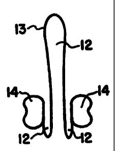
Figures 3A and 3B show the device (11) of the
present invention in the open or relaxed (Figure 3A)
and in the compressed forms (Figure 3B), thereby
revealing the formation of pouches (12) of dome (13)
material formed and held above and below the plane
of the rim (14) by lateral compression of the rim
(14).
Figures 4A-D show partial cross-sectional views
of rim shapes that form a stable contact when the
rim (14) is compressed.
Figures 5A and 5B show partial cross-sectional
views of alternative shapes of the outer surface of
the rim (14).
Figures 6A-D shows top-down (Figures 6A and 6C)
and cross-sectional views (Figures 6B and 6D) of the
device (11) of the present invention in its package
(15), thereby revealing the device (11) held without
- 11 -
CA 02308293 2000-04-28
WO 99/24085 PCT/US98/23868
lateral compression (Figures 6A and 6B) and an
alternative package shape that holds the device (11)
in partial compression (Figures 6C and 6D).
Figures 7A shows a side view of compressed rim
(14) held above package tray (16) to reveal that
lateral compression induces a slight downward arcing
of the rim (14) due to the elastic constraints of
the dome. Figure 7B shows that the rim (14) is then
pressed downward, forcing the arced-rim flat against
the flat bottom of the tray (16). The downward
arcing of the ends increases the downward force at
these ends, thus equalizing the force along the
entire rim and more efficiently removing agent from
the tray bottom.
DETAILED DESCRIPTION OF THE PREFERRED EMBODIMENT
The present invention discloses a device, a kit
and a method for simultaneously delivering at least
one beneficial agent to both the cervical and
vaginal lumen sides of a vagina. The device is made
of a flexible circular rim and a flexible dome. The
device can exist in either a relaxed state or in a
compressed state. In the compressed state, three
pouches are formed for carrying and delivering of
the beneficial agent to both the cervical and
vaginal lumen sides of the vagina.
DEVICE: The device (11) comprises a flexible
- 12 -
CA 02308293 2000-04-28
WO 99/24085 PCT/US98/23868
circular rim (14) with a flexible dome (13) attached
at its margin to the rim. A beneficial agent is
applied to both surfaces of the dome. The device
delivers a large volume of agent to all regions of
the vagina by preventing wipe-off of the agent from
both sides of the device during insertion.
Prevention of wipe-off at the vaginal introitus is
achieved by shaping and positioning the dome so that
it forms pouches by folding above and below the rim
as the rim is compressed in preparation for vaginal
insertion (see Figures 3A and 3B). The agent
sequestered in these pouches is not wiped off during
insertion regardless of the tone of the
circumvaginal sphincter. Not only does this assure
delivery of the desired dose, it reduces the waste
and resulting messiness of agent accumulating at the
introitus and on the fingers. Finally, the device
not only prevents wipe-off of the agent during
insertion but since the rim expands when the device
is inside the vagina, the design spreads the agent
to both cervical and non-cervical regions of the
vagina. Since the rim expands upon being inserted,
the agent is not permanently sequestered in an
inaccessible fold or cul-de-sac.
When the device is removed, it is advantageous
if the device will remove as much of the "spent" or
used up agent as possible, so that it will not be
- 13 -
CA 02308293 2000-04-28
WO 99/24085 PCT/US98/23868
absorbed or exit the vagina as a vaginal discharge.
With a contraceptive product, it is also useful if
the device can remove as much semen as possible from
the vagina when the device is removed postcoitally.
This again reduces vaginal discharge and can reduce
the risk of conception or transmission of STD
pathogens contained in the semen. This desirable
effect can be enhanced by employing a rim cross-
sectional profile with an elongated aspect ratio,
that is, one with a height greater than its width
(see Figures 3A-3B, 4A-4D and 5A-5B). The elongated
aspect ratio of the rim provides a spatula or
squeegee-like effect which gently wipes the agent
and semen from the vaginal mucosa as the device is
withdrawn.
Another advantage of elongating the cross-
sectional profile in the vertical dimension is to
reduce the tendency of the rim to arc (downward from
the plane of the rim) during compression. 0-rings
and similarly many contraceptive diaphragms with
rims that have a circular cross-sectional profile,
arc dramatically when compressed laterally along a
diameter of their ring shape. This extreme arcing
makes them poorly suited for use with the package
described below. An elongated profile, greater than
about 1.5:1 (height:width) shows a reduced tendency
to arc in comparison with a circular cross-sectional
- 14 -
CA 02308293 2000-04-28
WO 99/24085 PCT/US98/23868
profile. To avoid excessive arcing, it is also
necessary to shape the attached dome with sufficient
slack to prevent stretching of the dome from
inducing the rim to arc.
It is advantageous to shape the inner rim
surface so that the opposing rim surfaces that come
together as the device is compressed form a stable
contact, unlike the unstable configuration that
occurs when compressing a rim with a circular cross-
section. Several shapes that will achieve a stable
contact are illustrated in Figures 4A-4D. These
configurations prevent the rim from twisting into a
"figure-8" shape and allow a more secure grip on the
device. The height of this cross-sectional profile
should not exceed 12 mm, preferably not exceed 8 mm,
since otherwise, the device protrudes excessively
into the vaginal barrel and is more likely to
obstruct and be felt by the penis during
intercourse.
The outer rim surface should be shaped to avoid
any sharp edges. However, it may be advantageous to
provide one or more shallow grooves (17) in the
outer surface of the rim (14), as shown in the
examples drawn in Figures 5A and 5B. This provides
a more secure grip to the fingers as the device is
lifted out of the package. This gentle texturing
also helps to hold the anterior edge of the device
- 15 -
CA 02308293 2000-04-28
WO 99/24085 PCT/US98/23868
from slipping down from its stable position in the
vagina at the "pubic ledge" (see Figure 1).
The entire device can be fabricated by
injection molding using methods obvious to those
skilled in the art. A metal spring can be
incorporated into the rim during molding, as in
conventional diaphragms. Alternatively, the metal
spring can be omitted and the intrinsic resilience
of the material forming the rim can be relied on to
provide the requisite degree of stiffness to allow
insertion into and retention by the vagina. Or, the
rim can be injection molded separately and the
flexible dome attached by thermal, ultrasonic or
radio-frequency welding to the rim. A pre-shaped
dome can be thus attached or a flat film can be
attached and subsequently shaped by vacuum
thermoforming by methods well known in the art. The
device has the beneficial attribute that it will
deliver large quantities of an agent to all regions
of the vagina even if it is mistakingly inserted
upside down.
The materials for the rim and dome can be
chosen from many materials obvious to those skilled
in the art. These materials include but are not
limited to polyurethane, silicone, polyethylene,
styrene-ethylene-butylene-styrene block copolymer
(Krayton ) or ethylene vinyl acetate. These and
- 16 -
CA 02308293 2000-04-28
WO 99/24085 PCT/US98/23868
other materials can be used alone or in combination
and as multilayer laminates or as mixtures. The
stiffness required can be adjusted, by choice of
materials and material dimensions, according to
factors such as ease of insertion, comfort and
reliable retention within the vagina during wear
before and during intercourse, and ease of removal.
Experience with contraceptive diaphragms suggests
that the stiffness should be between 300 and 1000
grams compressive-force required to compress the rim
sides together.
PACKAGE: The package (15) used with the device
(11) is shaped to allow efficient retention of the
agent by both sides of the device as the device is
compressed and lifted from the package (see Figures
6A and 6B). Crucial elements for the package are a
substantially flat bottom to allow the agent to be
scooped up by the "squeegee action" of the device
rim and sufficient room for the elongation of the
device that occurs when the rim is compressed. This
allows the device to be compressed before lifting it
from the package. This in turn is also advantageous
in trapping the dome in the folded configuration
that prevents wipe-off of agent from both sides of
the dome.
The package holds the agent in place during
shipment and storage in the proper locations that
- 17 -
CA 02308293 2000-04-28
WO 99/24085 PCT/US98/23868
will allow efficient vaginal delivery. The package
also prevents the agent from coating the outer
portion of the rim contacted by the fingers. The
presence of agent on the rim might interfere with
the handling of the device by making it slippery.
Finally, the package is configured in a way that
guides the user in compressing the device and
picking it up in a orientation that allows for easy
and efficient vaginal insertion. For example,
finger detentes on the package can be used to guide
the user to compress the device at the intended
place. Figures 6A and 6B show the device (11) in
its package (15).
When used, the preloaded device-package
combination is opened by removing the top, for
example, by stripping back a foil-laminate film, to
expose the device (11) laying in the lower tray-like
packaging piece (16). The index finger and thumb
are placed in the detentes. The rim is pushed
downward to keep it in close contact with the bottom
of the tray and then the two opposing sides of the
rim are compressed inward. As the rim is
compressed, its bottom edge wipes up most of the
agent from the bottom of the tray.
A small amount of arcing of the rim during
compression (toward the lower edge of the rim that
presses against the lower tray-like packaging piece)
- 18 -
CA 02308293 2000-04-28
WO 99/24085 PCT/US98/23868
aids the process of loading agent into the device
from the package (see Figures 7A). Mild arcing in
this direction increases the force with which the
ends of the compressed rim press against the bottom
of the package tray. This improves the force
distribution along the bottom of the rim, making it
more nearly equal from the center (where the fingers
are pressing it down) out toward the tips (see
Figure 7B). This is analogous to the way camber in
alpine skis (arcing downward toward each end) is
used to apply more force to the tips and tails of
the skis than if the skis were flat. The result in
both cases is a more even force distribution along
the entire length of the bottom of the compressed
device.
Pressing the rim downward before and during the
rim compression also ensures that the central
upward-projecting portion of the dome will be
trapped (Figure 3B) within the opposed sides of the
rim brought together by the lateral compressing
movement. This holds this portion of the dome in
the upper pouch that will prevent wipe-off of the
agent from the inner surface of this upper pouch
during vaginal insertion.
The cavity in the package tray element can be
shaped in an oval that will hold the device
partially compressed. This has the advantage of
- 19 -
CA 02308293 2000-04-28
WO 99/24085 PCT/US98/23868
reducing the overall volume of the package since
less empty space is enclosed by the package (see
Figure 6B). This reduces the amount of dead-space
inside the package. (Dead-space increases the
amount of air sealed in the package and may reduce
the shelf-life of the beneficial agent.) Using a
more narrow oval tray cavity also reduces the span
over which the flexible top packaging piece must be
stretched and thus can reduce the thickness of
material that must be employed for this piece.
Finally, the narrower oval improves the visual
appeal and handling ease of the package since
bulkiness is reduced, and the positions at which to
laterally compress (squeeze) the device are more
obvious.
Most of any agent that is adherent to the top
member of the package can be transferred downward
onto the device by the following maneuver. The
bottom of the package is struck forcefully against a
hard surface or against ones other hand before
opening the package. The sudden deceleration of the
package and its contents causes most of any agent
adherent to the top member to move downward onto the
device.
Thus, this device-package combination provides
a simple and efficient means of transferring most of
any agent adherent to either the top or the bottom
- 20 -
CA 02308293 2000-04-28
WO 99/24085 PCT/US98/23868
package component to the device in preparation for
insertion into the vagina. This not only minimizes
waste but improves reproducibility in applying a
specific chosen dose of the agent.
The following examples are intended to
illustrate the present invention more practically
but not to limit it in any way.
$%A14PLE 1
Example 1 tests the ability of a preferred
embodiment of the present invention (designated
RPTcup, with a rim height of 8 mm, rim width of 4
mm, and a dome shape as illustrated in Figure 3) to
deliver a beneficial agent (BufferGelTM, an aqueous
vaginal contraceptive and microbicidal gel, U.S.
Patent 5,617,877) after preloading the agent on the
vaginal lumen side of the device. The agent was
loaded into the large pod projecting through the
plane of the rim, the rim was compressed around the
agent, and the compressed device was inserted into
an artificial vagina.
The artificial vagina was designed to mimic the
human vagina's internal pressure, and the
constriction at the opening of the vagina provided
by the introital sphincter. It consists of a water-
filled tank with a 1.25 inch inside diameter hollow
cylinder mounted horizontally in a hole on one side
of the tank to mimic the vaginal introitus. A
- 21 -
CA 02308293 2000-04-28
WO 99/24085 rcr/US99/23968
female condom (Reality , Female Health Company) was
attached to the cylinder, projecting into the tank,
mimicking the vagina with its flexible wall. To
serve as a constriction that mimics the introital
(circumvaginal) sphincter, an elastic band was
placed around the female condom near the attachment
site on the cylinder. The tank was filled with
water to a depth 4 cm above the center of the
cylinder. The water pressure mimics compression on
the vaginal walls caused by the woman's
intrabdominal pressure.
The amount of gel delivered was determined by
collecting and weighing all gel that failed to enter
the artificial vagina (gel left on the inserting
fingers, and at the opening of the artificial
vagina). The weight of this non-inserted gel was
subtracted from the weight of gel that had been
loaded on the device to calculate the amount of gel
delivered to the interior. The data in Table 1 were
generated as described above, and each value shown
is the mean value of three replicate determinations.
TABLE 1
Device Used Gel Loaded Gel Delivered Gel
Wasted
RPTcup 7.2 grams 6.8 grams 0.4
grams
- 22 -
CA 02308293 2000-04-28
WO 99/24085 PCT/US98/23868
Thus, Table 1 shows that when loaded with 7.2
grams of gel on the vaginal lumen side, RPTcup
delivers 6.8 grams, and wastes (fails to deliver)
only 0.4 grams.
EXAMPLE 2
Example 2 tests the ability of RPTcup to
deliver gel loaded simultaneously on both its
vaginal lumen side and cervical side. Equal
quantities of BufferGelTM were loaded on each side of
the device, either approximately 5 grams or
approximately 7 grams on a side. Delivery to the
artificial vagina was tested as described in Example
1. The data in Table 2 were generated as described
above and each value shown is the mean value of
three replicate determinations.
TABLE 2
Device Used Gel Loaded Gel Delivered Gel Wasted
RPTcup 10.04 grams 9.90 grams 0.14
grams
RPTcup 14.05 grams 13.95 grams 0.10
grams
Thus, Table 2 shows that RPTcup efficiently
delivers gel loaded on both sides, with minimal
waste.
- 23 -
CA 02308293 2000-04-28
WO 99/24085 PCTIUS98/23868
EXAMPLE 3
Example 3 tests the ability of the combination
of RPTcup and its package (15) to make it possible
to deliver a beneficial agent (BufferGelTM) on the
vaginal lumen side when using a preloaded-device
supplied in a package. The agent was loaded onto
the vaginal lumen side of the device as in Example
1, and now both device and agent loaded into the
package (15).
The device rim was pushed downward to keep it
in close contact with the bottom of the tray, and
then the rim was compressed laterally inward. As
the rim was compressed, its bottom edge wiped up the
agent from the bottom of the tray. The device and
the agent it contained were lifted free of the
package (15), and inserted into an artificial vagina
as in Example 1.
The amount of gel delivered was determined by
collecting and weighing all gel that failed to enter
the artificial vagina (gel left on the package, on
the inserting fingers, and at the opening of the
artificial vagina). The weight of this non-inserted
gel was subtracted from the weight of gel that had
been loaded on the device to calculate the amount of
gel delivered to the interior of the artificial
vagina.
Two other contraceptive diaphragms (Ortho ALL-
- 24 -
CA 02308293 2000-04-28
WO 99/24085 PCT/US98/23868
FLEX -70, Ortho Pharmaceutical, and Semina-70,
Semina Industria e Comercio Ltda.) were tested in
the same fashion for their ability to deliver gel on
their vaginal lumen (convex) side when loaded with
.gel into the package (15). The data in Table 3 were
generated as described above, and each value shown
is the mean value of three replicate determinations.
TABLE 3
Device Used Gel Loaded Gel Delivered Gel
Wasted
Ortho ALL FLEX-70 7.1 grams 2.9 grams 4.2
grams
Semina (70 mm) 7.0 grams 4.0 grams 3.0
grams
RPTcup 7.1 grams 6.0 grams 1.1
grams
Table 3 thus shows that when loaded with 7.1
grams of gel, RPTcup as packaged in the kit delivers
6 grams of gel, and wastes only 1.1 grams of the
gel. In contrast, conventional diaphragms (that do
not allow efficient "squeegee action" to remove gel
from the bottom of the package) deliver
substantially less gel, and waste substantially
more.
While the invention has been described in
connection with what is presently considered to be
the most practical and preferred embodiments, it is
to be understood that the invention is not limited
- 25 -
CA 02308293 2006-02-22
WO 99/24085 PCT/US98123868
to the disclosed embodiments, but on the contrary is
intended to cover various modifications and
equivalent arrangements included within the spirit
and scope of the appended claims.
Thus, it is to be understood that variations in
the present invention can be made without departing
from the novel aspects of this invention as defined
in the claims.
-26-