Note: Descriptions are shown in the official language in which they were submitted.
CA 02308383 2000-04-27
WO 99/Z2806 PCT/AU97/00737
PACKAGING AND COATING FOR BIO-ELECTRICAL STIMULATION
AND RECORDING ELECTRODES
Background of the Invention
A. Meld of Invention
This invention relates to packaging for a bioelectrical electrode array,
which can be used for stimulation, recording, or both, and more specifically,
to a
packaging system which includes a conductive liquid for ensuring electrical
contact with the electrode that is bathed in the liquid.
B. Description of the Prior Art
A cochlear device is generally understood to be some type of implantable
hearing aid which helps a specific class of patients for which conventional
hearing aids are inadequate. As is well known, a cochlear device includes an
electrode array of one or more electrodes which must perform appropriately for
the device to function.
Typically, the electrode or electrodes of a cochlear device may need to be
remotely tested for open circuits after packaging. It is believed that one
prior art
packaging included a sealed compartment of saline solution. The sealed
compartment, however, could only be ruptured once in order to enable
electrical
contact between electrodes, and thereby enable testing for open circuit
electrodes. In particular, in such a package the water content will evaporate
after
the compartment is ruptured -- the test is thus essentially a "once only" test
for
open circuits. In other words, it cannot be conducted both immediately after
packaging and immediately prior to implantation if the intervening time has
been
sufficient to allow water evaporation.
Additionally, prior art packaging is known which includes a coating
material made of polyvinyl alcohol. The polyvinyl alcohol is used to protect
the
electrode material. However, polyvinyl alcohol is not conductive, making
electrode testing even more difficult. Moreover, polyvinyl alcohol increases
the
stiffness of the electrode material and makes its insertion more difficult.
U.S. Patent No. 5,237,991 discloses a means for testing an electrical Lead
within its sterile package. The described device requires a dummy load to be
connected to the electrodes within the sterile package by means of posts and
CA 02308383 2000-04-27
WO 99/22806 PCT/AU97/00737
2
setscrews. However such hardware adds complexity and expense to the device.
Furthermore there is a risk of damage to the electrodes and inconvenience in
that the dummy load must be removed before making use of the lead.
Accordingly, it is desirable to provide a packaging system that overcomes
the above disadvantages. Furthermore, multiple electrodes are used in
biomedical applications apart from cochlear implants and so it is desirable to
provide a packaging which is also suitable for use with these other types of
electrodes.
Summary of the Ir~yention
Generally speaking, in accordance with the invention, a packaging
system for a bioelectrical stimulating and recording electrode is provided.
The
system includes a protective container, preferably semi-porous, in which the
electrode is housed. A conductive biocompatible and bioresorbable liquid
partially or wholly fills the container in order for the electrode housed
therein to
be coated by the liquid. While the preferred conductive liquid is a solution
of 1
by weight sodium chloride in glycerol, other liquids may be chosen for
practicing
the invention.
It is therefore an object of the invention to provide an improved packaging
system for a bioelectrical stimulating and recording electrode array.
Still another object of the invention is to provide electrical contact
between the electrodes of an array such that electrical contact will remain
after a
cochlear device has been packaged.
Yet a further object of the invention is to provide a method for testing the
operability of an electrode of a cochlear device.
Still other objects and advantages of the invention will in part be obvious,
and will in part be apparent from the following description.
An advantage of the invention is that glycerol is a lubricative liquid which
is currently used to allow deeper insertion of electrode arrays into the
cochlear.
The invention accordingly comprises a product and system possessing the
features, properties and relation of components which will be exemplified in
the
product and system hereinafter described, and the scope of the invention will
be
indicated in the claims.
CA 02308383 2000-04-27
wo ~na~o~ rcTiAU9~roms~
3
Brief DescriQtign of the Drawings
For a fuller understanding of the invention, reference is made to the
following description, taken in connection with the accompanying drawings, in
which:
Fig. 1 is a cross-sectional view showing a bioelectrical stimulation and
recording electrode contained in a packaging system made in accordance with
the invention;
Fig. 2 shows an enlarged view of the electrode array.
Fig. 3 is an electrical schematic view.
Detailed Description of the Preferred Embodiment
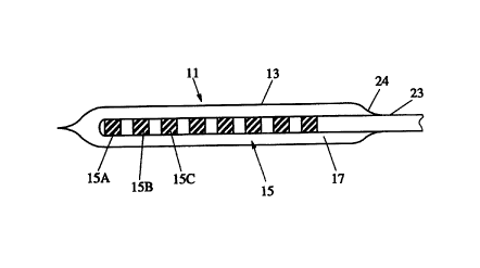
Referring first to Fig. 1, a packaging system generally indicated at 11 and
made in accordance with the invention is now described. Packaging system 11
includes a protective container 13 in which a bioelectrical stimulating and
recording electrode 15 is housed. The container 13 may constitute the whole
package or it may form a separate compartment within a larger package.
Container 13 may have a substantially tubular configuration and is made from
silicone, or other similar material. Preferably, container or tube 13 is made
of a
semi-porous material which is substantially permeable to a sterilizing media
such as ETO/steam. Preferably container 13 takes the form of a tear-away
sheath.
Packaging system 11 further includes a conductive biocompatible and
bioresorbable liquid 17 for at least partially filling container 13. As can be
appreciated, liquid 17 coats or otherwise bathes electrode array 15, including
electrodes 15A-15C and others, as it is situated in container 13.
Preferably, liquid 17 should have a boiling point significantly greater than
that of water and a vapor pressure at storage temperature significantly less
than
that of water. Such properties reduce the likelihood of evaporation during
storing
of packaging system 11.
Liquid 17 is held within the container by a seal 24 around the electrode
array body 23 which is impermeable to the liquid. Alternatively, a larger
container may be used for housing the complete electrode assembly. Of most
importance is for liquid 17 to be conductive so that electrode array 15 can be
CA 02308383 2000-04-27
WO 99/Z2806 PGT/AU97/00737
4
tested for open circuits after packaging within system 11 as described below.
The preferred liquid 17 is saline-doped glycerol, i.e., a solution of 1%
sodium
chloride in glycerol, since it is substantially conductive and is more pliable
than
polyvinyl alcohol. Although saline-doped glycerol is the preferred liquid 17,
other
suitable high-boiling point biocompatible solvents include polyethylene
glycol,
propylene glycol, hyaluronic acid, and hydroxypropyl methyicellulose.
Alternatively, a liquid containing biocompatible salts, such as potassium
chloride, sulfates, nitrites and phosphates, may be used.
As can be well appreciated, mixtures of more than one of these suitable
liquids may be used, and some water may be added, or even small amounts of
polyvinyl alcohol may be added.
An important feature of the inventive system is that it enables remote
testing of packaged bioelectrical stimulating and recording electrodes. This
is
because the liquid which bathes the electrodes in the packaging of the
invention
is both conductive and pliable.
Referring to Fig. 2, a typical array 15 includes a plurality of electrodes
15A, 15B, etc. disposed near a distal end. Each electrode is connected to a
corresponding wire 21 A, 21 B, etc. extending through a sleeve 23 and being
exposed at end 25.
Since all the electrodes are bathed in the liquid 17, they are effectively
shorted to each other. Therefore, the electrodes can be easily tested for
continuity. For example, a shown in Fig. 3, each electrode and its conductor
can
be tested by checking the continuity between 21 A, 21 B ... and 21 D, which
may
be considered a common return. Typically a limited current source and ammeter
or continuity tester 19 are used to test for electrical continuity.
If the array has only a single electrode, it may be tested by using liquid 17
for the return path. For example, a method for testing the electrical
integrity of an
implantable electrode array might consist of the following steps. Firstly the
electrode bearing portion of the array is housed in a protective container
containing an electrically conductive liquid. The array, container and liquid
are
arranged so that the electrodes are in electrical contact with the liquid
while the
electrode leads are allowed to protrude with the electrically conductive
liquid
CA 02308383 2000-04-27
wo ~nzso6 pcriAU9~roo~a~
being substantially sealed within the container as shown in Fig 1 for example.
The next step is that for each electrode a current is passed between the lead
connecting to that electrode and one of the other electrode leads. If current
flows
through the circuit, as might be detected with a conventional ammeter for
5 example, then it can be deduced that the leads are intact and electrically
connected to the electrodes, otherwise a problem is detected and the electrode
array can be either disposed of or repaired. Packaged arrays which have tested
satisfactorily are then stored until such time as they are required.
Prior to implantation the packaged electrode arrays can be re-tested,
once again by connecting a current source between the various electrode leads
and monitoring for current flow as before. On the basis of the monitoring it
can be
decided if the electrode array is suitable for implantation.
It will thus be seen that the objects set forth above, among those made
apparent from the preceding description, are efficiently obtained and, since
certain changes may be made in the above system without departing from the
spirit and scope of the invention, it is intended that all matter contained in
this
description and shown in the accompanying drawings shall be interpreted as
illustrative and not in a limiting sense.
!t is also to be understood that the following claims are intended to cover
all of the generic and specific features of the invention herein described,
and all
statements of the scope of the invention which, as a matter of language, might
be
said to fall therebetween.