Note: Descriptions are shown in the official language in which they were submitted.
CA 02308427 2000-OS-10
.~'~."' O ~ ~-~7~'-k00
TITLE OF THE INVENTION
OPTICAL OUTPUT ADJUSTMENT APPARATUS AND OPTICAL OUTPUT
ADJUSTMENT METHOD
BACKGROUND OF THE INVENTION
Field of the Invention
The present invention relates to an optical output adjustment apparatus and
an optical output adjustment method for adjusting an optical output level of a
reproducing laser used for reproducing a record mark recorded on a magneto-
optical recording medium.
Description of Related Art
In recent years, attention has been paid to a magneto-optical disk as a high-
density recording medium which enables rewriting of information signals. For
example, the Japanese Patent Application KOKAI Publication No. 6-290496
(hereinafter called a reference 1) discloses a magneto-optical reproducing
method
which utilizes a point that a magneto-optical disk including at least three
layers of a
displacement layer, a switching layer, and a memory layer as magnetic layers
are
used so that the size of magnetic sectors recorded on the memory layer is
substantially magnified on the moving layer. For example, the magneto-optical
reproducing method is a so-called DWDD (Domain Wall Displacement Detection)
in which a reproducing laser beam is irradiated during reproducing such that
an
area in the switching layer is set to a curie temperature or more, and
magnetic
CA 02308427 2000-OS-10
connection between the memory layer and the displacement layer, which
corresponds to the area, is disconnected to detect a magnetic wall which moves
within the area of the moving layer corresponding to an area where the
magnetic
connection is disconnected. In this manner, the size of the magnetic sectors
recorded on the memory layer is substantially magnified on the displacement
layer
to enlarge the reproducing carrier signal.
In the magneto-optical reproducing method based on this DWDD, i.e., in a
so-called magnetic wall displacement detection reproducing method (hereinafter
called a DWDD reproducing method), it is possible to reproduce a very large
information signal even fi om an optical limit resolution of a reproducing
laser, so
the recording density can be heightened without changing the wavelength of the
reproducing laser beam and the numerical aperture NA of the objective leans.
Meanwhile, in the DWDD reproducing method, the output level of the
reproducing laser beam must be set to a certain level which causes magnetic
displacement. However, no optimal output level for the reproducing laser beam
has
been known. This is because the optimal output level differs depending on the
conditions such as a peripheral temperature change, variants of sensitivity of
between magneto-optical disks, and the like. However, if the optimal value of
the
output level of the reproducing laser beam cannot be grasped and the output
level
of the reproducing laser beam is too large, record marks recorded on adjacent
recording tacks may be deteriorated.
2
CA 02308427 2000-OS-10
BRIEF SUMMARY OF THE INVENTION
Hence, the present invention has been made in view of the above situation
and has an object of providing an optical output adjustment apparatus and an
optical output adjustment method which are capable of adjusting a reproducing
the
reproducing laser beam to an optimal output level.
To achieve the above object, an optical output adjustment apparatus
according to the present invention is constructed as an apparatus for
adjusting an
output level of a reproducing laser beam, in a signal reproducing device which
adopts a magnetic wall movement detection reproducing method, irradiates the
reproducing laser beam onto a magneto-optical information recording medium on
which data is recorded by recording marks having different recording lengths
according to a predetermined modulation method, and magnifies a magnetic
sector
by magnetic wall movement, thereby to perform reproducing of the data.
The oprical output adjustment apparatus comprises: a light source for
emitting the reproducing laser beam; reproducing signal detector means for
detecting a shortest recording mark reproducing signal corresponding to a
component of a shortest recording mark in a reproducing signal obtained by
reproducing the magneto-optical information recording medium; signal amplitude
level detector means for detecting an amplitude level of the shortest
recording mark
reproducing signal; comparator means for comparing the amplitude level with a
predetermined threshold value; and optical output control means for adjusting
the
3
CA 02308427 2000-OS-10
reproducing laser beam to an output level which makes the amplitude level
equal to
or higher-than the predetermined threshold value.
In the optical output adjusrinent apparatus having the structure as described
above, based on a comparison result between a predetermined threshold value
and
an amplitude level of a shortest recording mark reproducing signal
corresponding to
a component of a shortest recording mark in a reproducing signal obtained by
reproducing the magneto-optical information recording medium, the reproducing
laser beam is adjusted to an output level which makes the amplitude level
equal to
or higher than the predetennined threshold value.
By the reproducing laser beam whose output level is thus controlled, it is
possible to obtain a reproducing signal with a lowered fitter. '
Also, to achieve the above object, an optical output adjustment method
according to the present invention is a method for adjusting an output level
of a
reproducing laser beam, in a signal reproducing device which adopts a magnetic
wall movement detection reproducing method, irradiates the reproducing laser
beam onto a magneto-optical information recording medium on which data is
recorded by recording marks having different recording lengths according to a
predetermined modulation method, and magnifies a magnetic sector by magnetic
wall movement, thereby to perform reproducing of the data, characterized in
that,
based on a comparison result between a predetermined threshold value and an
amplitude level of a shortest recording mark reproducing signal corresponding
to a
4
CA 02308427 2000-OS-10
component of a shortest recording mark in a reproducing signal obtained by
reproducing the magneto-optical information recording medium, the reproducing
laser beam is adjusted to an output level which makes the amplitude level
equal to
or higher than the predetermined threshold value.
By the reproducing laser beam whose output level is thus controlled, it is
possible to obtain a reproducing signal with a lowered fitter.
Also, to achieve the above object, an optical output adjustment apparatus
according to the present invention is constructed as an apparatus for
adjusting an
output level of a reproducing laser beam, in a signal reproducing device which
adopts a magnetic wall movement detection reproducing method, irradiates the
reproducing laser beam onto a magneto-optical information recording medium on
which data is recorded by recording marks having different rccording lengths
according to a predetermined modulation method, and magnifies a magnetic
sector
by magnetic wall movement, thereby to perform reproducing of the data.
The optical output adjustment apparatus comprises: a light source for
emitting the reproducing laser beam; first reproducing signal detector means
for
detecting a first recording mark reproducing signal corresponding to a
component
of a first recording mark in a reproducing signal obtained by reproducing the
magneto-optical information recording medium; second reproducing signal
detector
means for detecting a second recording mark reproducing signal corresponding
to a
component of a second recording mark in a reproducing signal obtained by
CA 02308427 2000-OS-10
reproducing the magneto-optical information recording medium; first signal
amplitude level detector means for detecting a first amplitude level of the
first
recording mark reproducing signal; second signal amplitude level detector
means
for detecting a second amplitude level of the second recording mark
reproducing
signal; difference value calculator means for calculating a difference value
between
the first and second amplitude levels; comparator means for comparing the
amplitude level with a predetermined threshold value; and optical output
control
means for adjusting the reproducing laser beam to an output level which makes
the
amplitude level equal to or lower than the predetermined threshold value.
In the optical output adjustment apparatus having the structure as described
above, based on a comparison result between a threshold value and a difference
value between first and second amplitude Ievels of first and second recording
mark
reproducing signals corresponding to components of first and second recording
marks having lengths different from each other in a reproducing signal
obtained by
reproducing the magneto-optical information recording medium, the reproducing
laser beam is adjusted to an output level which makes the amplitude level
equal to
or lower than the predetermined threshold value.
By the reproducing laser beam whose output level is thus controlled, it is
possible to obtain a reproducing signal with a lowered fitter.
Also, to achieve the above object, an optical output adjustment method
according to the present invention is a method for adjusting an output level
of a
6
CA 02308427 2000-OS-10
reproducing laser beam, in a signal reproducing device which adopts a magnetic
wall movement detection reproducing method, irradiates the reproducing laser
beam onto a magneto-optical information recording medium on which data is
recorded by recording marks having different recording lengths according to a
predetermined modulation method, and magnifies a magnetic sector by magnetic
wall movement, thereby to perform reproducing of the data, characterized in
that,
based on a comparison result between a threshold value and a difference value
between first and second amplitude levels of first and second recording mark
reproducing signals corresponding to components of first and second recording
marks having lengths different from each other in a reproducing signal
obtained by
reproducing the magneto-optical infonnation recording medium, the reproducing
laser beam is adjusted to an output level which makes the amplitude level
equal to
or lower than the predetermined threshold value.
By the reproducing laser beam whose output level is thus controlled, it is
possible to obtain a reproducing signal with a lowered fitter.
Also, to achieve the above object, an optical output adjustment apparatus
according to the present invention is constructed as an apparatus for
adjusting an
output level of a reproducing laser beam, in a signal reproducing device which
adopts a magnetic wall movement detection reproducing method, irradiates the
reproducing laser beam onto a magneto-optical information recording medium on
which data is recorded by recording marks having different recording lengths
7
CA 02308427 2000-OS-10
according to a predeterniined modulation method, and magnifies a magnetic
sector
by magnetic wall movement, thereby to perform reproducing of the data.
The optical output adjustment apparatus comprises: a light source for
emitting the reproducing laser beam; reproducing signal detector means for
detecting a high-frequency reproducing signal consisting of a high-frequency
component in a reproducing signal obtained by reproducing the magneto-optical
information recording medium; signal amplitude level detector means for
detecting
an amplitude level of the high-frequency reproducing signal; comparator means
for
comparing the amplitude level with a predeterniined threshold value; and
optical
output control means for adjusting the reproducing laser beam to an output
level
which makes the amplitude level equal to or higher than the predetermined
threshold value.
In the optical output adjustment apparatus having the structure as described
above, based on a comparison result between a predetennined threshold value
and
an amplitude level of a high-frequency reproducing signal of a high-frequency
component in a reproducing signal obtained by reproducing the magneto-optical
information recording medium, the reproducing laser beam is adjusted to an
output
level which makes the amplitude level equal to or higher than the
predetermined
threshold value.
By the reproducing laser beam whose output level is thus controlled, it is
possible to obtain a reproducing signal with a lowered fitter.
CA 02308427 2000-OS-10
Also, an optical output adjustment method according to the present invention
is a method for adjusting an output level of a reproducing laser beam, in a
signal
reproducing device which adopts a magnetic wall movement detection reproducing
method, irradiates the reproducing laser beam onto a magneto-optical
infonnation
recording medium on 'which data is recorded by recording marks having
different
recording lengths according to a predetermined modulation method, and
magnifies
a magnetic sector by magnetic wall movement, thereby to perform reproducing of
the data, characterized in that, based on a comparison result between a
predetennined threshold value and an amplitude level of a high-frequency
reproducing signal of a high-frequency component in a reproducing signal
obtained
by reproducing the magneto-optical information recording medium, the
reproducing
laser beam is adjusted to an output level which makes the amplitude level
equal to
or higher than the predetennined threshold value.
By the reproducing laser beam whose output level is thus controlled, it is
possible to obtain a reproducing signal with a lowered fitter.
Alsd, to achieve the above object, an optical output adjustment apparatus
according to the present invention is constructed as an apparatus for
adjusting an
output level of a reproducing laser beam, in a signal reproducing device which
adopts a magnetic wall movement detection reproducing method, irradiates the
reproducing laser beam onto a magneto-optical information recording medium on
which data is recorded by recording marks having different recording lengths
9
CA 02308427 2000-OS-10
according to a predetermined modulation method, and magnifies a magnetic
sector
by magnetic wall movement, thereby to perform reproducing of the data.
The optical output adjustment apparatus comprises: a light source for
emitting the reproducing laser beam; differentiator means for differentiating
a
reproducing signal obtained by reproducing the magneto-optical information
recording medium, thereby to output a differential signal; signal amplitude
level
detector means for detecting an amplitude level of the differential signal;
comparator means for comparing the amplitude level with a predetermined
threshold value; and optical output control means for adjusting the
reproducing
laser beam to an output level which makes the amplitude level equal to or
higher
than the predetermined'threshold value.
In the optical output adjustment apparatus having the structure as described
above, based on a comparison result between a predetermined threshold value
and
an amplitude level of a differential signal obtained by differentiating a
reproducing
signal obtained by reproducing the magneto-optical information recording
medium,
the reproducing laser beam is adjusted to an output level which makes the
amplitude level equal to or higher than the predetermined threshold value.
By the reproducing laser beam whose output level is thus controlled, it is
possible to obtain a reproducing signal with a lowered fitter.
Also, an optical output adjustment method according to the present invention
is a method for adjusting an output level of a reproducing laser beam; in a
signal
CA 02308427 2000-OS-10
reproducing device which adopts a magnetic wall movement detection reproducing
method, irradiates the reproducing laser beam onto a magneto-optical
information
recording medium on which data is recorded by recording marks having different
recording lengths according to a predetermined modulation method, and
magnifies
a magnetic sector by magnetic wall movement, thereby to perform reproducing of
the data, characterized in that, based on a comparison result between a
predetermined threshold value and an amplitude level of a differential signal
obtained by differentiating a reproducing signal obtained by reproducing the
magneto-optical information recording medium, the reproducing laser beam is
adjusted to an output level which makes the amplitude level equal to or higher
than
the predetermined threshold value. '
By the reproducing laser beam whose output level is thus controlled, it is
possible to obtain a reproducing signal with a lowered fitter.
Also, to achieve the above object, an optical output adjustment apparatus
according to the present invention is constructed as a method for adjusting an
output level of a reproducing laser beam, in a signal reproducing device which
adopts a magnetic wall movement detection reproducing method, irradiates the
reproducing laser beam onto a magneto-optical information recording medium on
which data is recorded on a data area by recording marks having different
recording
lengths according to a predetermined modulation method and a reproducing power
adjustment repetitive pattern constructed only by shortest marks is written in
a
11
CA 02308427 2000-OS-10
reference area, and magnifies a magnetic sector by magnetic wall movement,
thereby to perform reproducing of the data.
The optical output adjustment apparatus comprises: a light source for
emitting the reproducing laser beam; reproducing signal detector means for
detecting a power adjustment reproducing signal obtained by reproducing the
reproducing power adjustment repetitive pattern; signal amplitude level
detector
means for detecting an amplitude level of the power adjustment reproducing
signal;
comparator means for comparing the amplitude level with a predetermined
threshold value; and optical output control means for adjusting the
reproducing
laser beam to an output level which makes the amplitude level equal to or
higher
than the predetermined threshold value.
In the optical output adjustment apparatus having the structure as described
above, based on a comparison result between a predetermined threshold value
and
an amplitude level of a power adjustment reproducing signal obtained by
reproducing the reproducing power adjustment repetitive pattern, the
reproducing
laser beam is adjusted to an output level which makes the amplitude level
equal to
or higher than the predetermined threshold value.
By the reproducing laser beam whose output level is thus controlled, it is
possible to obtain a reproducing signal with a lowered fitter.
Also, to achieve the above object, an optical output adjustment method
according to the present invention is a method for adjusting an output level
of a
12
CA 02308427 2000-OS-10
reproducing laser beam, in a signal reproducing device which adopts a magnetic
wall movement detection reproducing method, irradiates the reproducing laser
beam onto a magneto-optical information recording medium on which data is
recorded on a data area by recording marks having different recording lengths
according to a predeterniined modulation method and a reproducing power
adjustment repetitive pattern constructed only by shortest marks is written in
a
reference area, and magnifies a magnetic sector by magnetic wall movement,
thereby to perform reproducing of the data, characterized in that, based on a
comparison result between a predetermined threshold value and an amplitude
level
of a power adjustment reproducing signal obtained by reproducing the
reproducing
power adjustment repetitive pattern, the reproducing laser beam is adjusted to
an
output level which makes the amplitude level equal to or higher than the
predetermined threshold value.
By the reproducing laser beam whose output level is thus controlled, it is
possible to obtain a reproducing signal with a lowered fitter.
Also, to achieve the above object, an optical output adjustment apparatus
according to the present invention is constructed as an apparatus for
adjusting an
output level of a reproducing laser beam, in a signal reproducing device which
adopts a magnetic wall movement detection reproducing method, irradiates the
reproducing laser beam onto a magneto-optical information recording medium on
which data is recorded in a data area by recording marks having different
recording
13
CA 02308427 2000-OS-10
lengths according to a predetermined modulation method and a reproducing power
adjustment pattern constructed only by first and second marks having different
lengths is written in a reference area, and magnifies a magnetic sector by
magnetic
wall movement, thereby to perform reproducing of the data.
The optical output adjustment apparatus comprises: a light source for
emitting the reproducing laser beam; first reproducing signal detector means
for
detecting a first mark reproducing signal corresponding to a component of the
first
mark in a power adjustment reproducing signal obtained by reproducing the
reproducing power adjustment pattern; second reproducing signal detector means
for detecting a second mark reproducing signal corresponding to a component of
the second mark in a power adjustment reproducing signal obtained by
reproducing
the reproducing power adjustment pattern; first signal amplitude level
detector
means for detecting an amplitude level of the first mark reproducing signal;
second
signal amplitude level detector means for detecting an amplitude level of the
second
mark reproducing signal; difference value calculator means for calculating a
difference value between the first and second amplitude levels; comparator
means
for comparing the difference value with a predetermined threshold value; and
optical output control means for adjusting the reproducing laser beam to an
output
level which makes the amplitude level equal to or lower than the predetermined
threshold value.
In the optical output adjustment apparatus having the structure 'as described
14
CA 02308427 2000-OS-10
above, based on a comparison result between a predetermined threshold value
and a
difference value between first and second amplitude levels of first and second
mark
reproducing signals corresponding to components of the first and second marks
obtained by reproducing the reproducing power adjustment pattern.
By the reproducing laser beam whose output level is thus controlled, it is
possible to obtain a reproducing signal with a lowered fitter.
Also, to achieve the above object, an optical output adjustment method
according to the present invention is a method for adjusting an output level
of a
reproducing laser beam, in a signal reproducing device which adopts a magnetic
wall movement detection reproducing method, irradiates the reproducing laser
beam onto a magneto-optical information recording medium on which data is
recorded in a data area by recording marks having different recording lengths
according to a predetermined modulation method and a reproducing power
adjustment pattern constructed only by first and second marks having different
lengths is written in a reference area, and magnifies a magnetic sector by
magnetic
wall movement, thereby to perform reproducing of the data, characterized in
that,
based on a comparison result between a predetermined threshold value and a
difference value between first and second amplitude levels of first and second
mark
reproducing signals corresponding to components of the first and second marks
obtained by reproducing the reproducing power adjustment pattern.
By the reproducing laser beam whose output level is thus controlled, it is
CA 02308427 2000-OS-10
possible to obtain a reproducing signal with a lowered fitter.
Also, to achieve the above object, an optical output adjustment apparatus
according to the present invention is constructed as an apparatus for
adjusting an
output level of a reproducing laser beam, in a signal reproducing device which
adopts a magnetic wall movement detection reproducing method, irradiates the
reproducing laser beam onto a magneto-optical information recording medium on
which data is recorded on a data area by recording marks having different
recording
lengths according to a predetermined modulation method and a reproducing power
adjustment repetitive pattern is written in a reference area, and magnifies a
magnetic sector by magnetic wall movement, thereby to perform reproducing of
the
data.
The optical output adjustment apparatus comprises: a light source for
emitting the reproducing laser beam; reproducing signal detector means for
detecting a high-frequency component in a power adjustment reproducing signal
obtained by reproducing the reproducing 'power adjustment repetitive pattern;
signal amplitude level detector means fir detecting an amplitude level of the
high-
frequency reproducing signal; comparator means for comparing the amplitude
level
with a predetermined threshold value; and optical output control means for
adjusting the reproducing laser beam to an output level which makes the
amplitude '
level equal to or higher than the predetermined threshold value.
In the optical output adjustment apparatus having the structure as described
16
CA 02308427 2000-OS-10
above, based on a comparison result between a predetermined threshold value
and
an amplitude level of a high-frequency reproducing signal consisting of a high-
frequency component in a power adjustment reproducing signal obtained by
reproducing the reproducing power adjustment repetitive pattern, the
reproducing
laser beam is adjusted to an output level which makes the amplitude level
equal to
or higher than the predetermined threshold value.
By the reproducing laser beam whose output level is thus controlled, it is
possible to obtain a reproducing signal with a lowered fitter.
Also, to achieve the above object, an optical output adjustment method
according to the present invention is a method for adjusting an output level
of a
reproducing laser beam, in a signal reproducing device which adopts a magnetic
wall movement detection reproducing method, irradiates the reproducing laser
beam onto a magneto-optical information recording medium on which data is
recorded on a data area by recording marks having different recording lengths
according to a predetermined modulation method and a reproducing power
adjustment repetitive pattern is written in a reference area, and magnifies a
magnetic sector by magnetic wall movement, thereby to perform reproducing of
the
data, characterized in that, based on a comparison result between a
predetermined
threshold value and an amplitude level of a high-frequency reproducing signal
consisting of a high-frequency component in a power adjustment reproducing
signal obtained by reproducing the reproducing power adjustment repetitive
17
CA 02308427 2000-OS-10
pattern, the reproducing laser beam is adjusted to an output level which makes
the
amplitude level equal to or higher than the predetermined threshold value.
By the reproducing laser beam whose output level is thus controlled, it is
possible to obtain a reproducing signal with a lowered fitter.
Also, to achieve the above object, an optical output adjustment apparatus
according to the present invention is constructed as an apparatus for
adjusting an
output level of a reproducing laser beam, in a signal reproducing device which
adopts a magnetic wall movement detection reproducing method, irradiates the
reproducing laser beam onto a magneto-optical information recording medium on
which data is recorded on a data area by recording marks having different
recording
lengths according to a predetennined modulation method and a reproducing power
adjustment pattern is written in a reference area, and magnifies a magnetic
sector
by magnetic wall movement, thereby to perform reproducing of the data.
The optical output adjustment apparatus comprises: a light source for
emitting the reproducing laser beam; differentiator means for differentiating
a
power adjustment reproducing signal obtained by reproducing the reproducing
power adjustment pattern, thereby to output a differential signal; signal
amplitude
level detector means for detecting an amplitude level of the differential
signal;
comparator means for comparing the amplitude level with a predetermined
threshold value; and optical output control means for adjusting the
reproducing
laser beam to an output level which makes the amplitude level equal to or
higher
18
CA 02308427 2000-OS-10
than the predetermined threshold value.
In the optical output adjustment apparatus having the structure as described
above, based on a comparison result between a predetermined threshold value
and
an amplitude level of a differential signal obtained by differentiating a
power
adjustment reproducing signal obtained by reproducing the reproducing power
adjustment pattern, the reproducing laser beam is adjusted to an output level
which
makes the amplitude level equal to or higher than the predetermined threshold
value.
By the reproducing laser beam whose output level is thus controlled, it is
possible to obtain a reproducing signal with a lowered fitter.
Also, to achieve the above object, an optical output adjustment method
according to the present invention is a method for adjusting an output level
of a
reproducing laser beam, in a signal reproducing device which adopts a magnetic
wall movement detection reproducing method, irradiates the reproducing laser
beam onto a magneto-optical information recording medium on which data is
recorded on a data area by recording marks having different recording lengths
according to a predetermined modulation method and a reproducing power
adjustment pattern is written in a reference area, and magnifies a magnetic
sector
by magnetic wall movement, thereby to perform reproducing of the data,
characterized iri that, based on a comparison result between a predetermined
threshold value and an amplitude level of a differential signal obtained by
19
CA 02308427 2000-OS-10
differentiating a power adjustment reproducing signal obtained by reproducing
the
reproducing power adjustment pattern, the reproducing laser beam is adjusted
to an
output level which makes the amplitude level equal to or higher than the
predetermined threshold value.
By the reproducing laser beam whose output level is thus controlled, it is
possible to obtain a reproducing signal with a lowered fitter.
BRIEF DESCRIPTION OF THE SEVERAL VIEWS OF THE DRAWING
FIG. 1(A) and FIG. 1(B) are characteristic graphs used for explaining
principles of an optical output adjustment method as an embodiment of the
present
invention and show relationships between the reproducing power, shortest
recording mark amplitude level, longest recording mark amplitude level, high-
frequency amplitude level, and fitter.
FIG. 2 is a characteristic graph showing an example of a reproducing signal
obtained by a shortest mark.
FIG. 3(A) and FIG. 3(B) are characteristic graphs used for explaining
principles of an optical output adjustment method as an embodiment of the
present
invention and show relationships between the reproducing power, differential
signal
amplitude level, and fitter.
FIG. 4 is a block diagram showing the structure of a magneto-optical disk to
which an optical output adjustment apparatus as an embodiment of the present
invention is applied.
CA 02308427 2000-OS-10
FIG. 5 is a plan view showing a magneto-optical disk having a reference area
where a pattern for reproducing power adjustment is written.
DETAILED DESCRIPTION OF THE INVENTION
In the following, embodiments of the present invention will be explained
more specifically with reference to the drawings. In the embodiments, the
present
invention is applied to an optical output adjustment method adjusts the output
level
(hereinafter called a reproducing power ) of a reproducing laser beam in a
magneto-
optical disk device in which the DWDD (Domain Wall Displacement Detection)
reproducing method is adopted and data is recorded by record marks having
different recording lengths according to a predetermined modulation method.
The optical output adjustment method controls the reproducing power, based
on the amplitude level of a signal extracted by various processing with
respect to a
reproducing signal of recording marks recorded on a magneto-optical disk. For
example, there are various recording methods for magneto-optical disks.
However,
in the present embodiment, explanation will be made of an optical output
adjustment method based on the 1-7 modulation method. r
According to a recording method based on the 1-7 modulation method,
where a window width corresponding to a channel clock is T, recording marks of
2T to 8T exist as recording marks having different recording lengths.
Therefore, in
case of the 1-7 modulation method, the recording mark of 2T is the shortest
recording mark which has the shortest recording length, and the recording mark
of
21
CA 02308427 2000-OS-10
8T is the longest recording mark which has the longest recording length. If
this 1-7
modulation method is adopted, data recorded on a magneto-optical disk is
expressed by the recording marks of 2T to 8T.
FIG. 1 (A) shows a relationship between the reproducing power of a light
source and the fitter of a reproducing signal. FIG. 1(B) shows amplitude
levels of
the shortest recording marks of 2T and 8T in a reproducing signal obtained by
reproducing a magneto-optical disk, and an amplitude level of a high-frequency
component of the recording mark of 2T, in case where the reproducing power is
desired to increase like FIG. 1(A). In the following, the recording mark of 2T
is
called a shortest recording mark, a reproducing signal corresponding to the
component of the shortest recording mark is called a shortest recording mark
reproducing signal, the amplitude level of the shortest recording mark
reproducing
signal is called a shortest recording mark amplitude level, the recording mark
of 8T
is called a longest recording mark, a reproducing signal corresponding to the
component of the longest recording mark is called a longest recording mark
reproducing signal, the amplitude level of the longest recording mark
reproducing
signal is called a longest recording mark amplitude level, and the amplitude
level of
the high-frequency component is called a high-frequency amplitude level.
As shown in FIG. 1(A), in the reproducing power, there is an area 0P
(hereinafter called a low fitter reproducing power) where excellent
reproducing is
enabled and the fitter is low. For example, in the present embodiment, the
lower
22
CA 02308427 2000-OS-10
fitter reproducing power 0P (e.g., the range of reproducing power indicated by
a
broken line in FIG. 1(A)) is set to about 1.4 to 2.0 mW.
Meanwhile, as shown in FIG. 1(B), if the reproducing power is increased
within a range like in FIG. 1(A), the longest recording mark amplitude level a
increases at first, and subsequently, the shortest recording mark amplitude
level b in
creases. If the reproducing power is further increased, the high-frequency
amplitude level c of the shortest recording mark increases. Further, the
shortest
recording mark amplitude level a, the longest recording mark amplitude level
b, and
the high-frequency amplitude level c of the shortest mark have maximum values
at
a reproducing power, and thereafter decrease as the reproducing power
increases.
Also, FIG. 2 shows an isolated pattern of the shortest recording mark
reproduced by the DWDD method. As shown in this FIG. 2, in the DWDD
reproducing method, a reproducing signal of the shortest recording mark has a
shape which is rather similar to a sine wave than a rectangular wave. For
example,
this is the same as the reproducing signal waveform disclosed in the Japanese
Patent Application KOKAI Publication No. 10-92037 which shows the DWDD
reproducing method. The high-frequency component of the reproducing signal of
the shortest recording mark described above is obtained as a result of
detecting an
edge component of this kind.
Thus, the shortest recording mark amplitude level a, the longest recording
mark amplitude level b, and the high-frequency amplitude level b of the
shortest
23
CA 02308427 2000-OS-10
recording mark reach a certain level or higher at the lower fitter reproducing
power
0P. That is, changes of the shortest recording mark amplitude level a, the
longest
recording mark amplitude level b, and the high-frequency amplitude level b of
the
shortest recording mark substantially are arranged to have quantitatively
equal
tendencies of increase at the lower fitter reproducing power DP and are at a
certain
level or higher at the low fitter reproducing power DP.
From the above, it is found that there is a certain relationship between
changes of the amplitude level of a reproducing signal of the recording mark
and
the j fitter.
Also, if the relationship between the changes of the fitter and the amplitude
level of the recording signal of the recording mark is considered in view of
the
recording length of the recording mark, the shortest recording mark amplitude
level
b has a higher correlation than the longest recording mark amplitude level a.
That
is, the change of the shortest recording mark amplitude level b substantially
corresponds qualitatively to the change of the fitter, at the low fitter
reproducing
power 0P.
In the optical output adjustment method according to the present invention,
the reproducing power is thus controlled, based on the amplitude level of the
reproducing signal of the recording mark having a higher correlation with the
change of the fitter.
An optical output adjustment method according to the first embodiment is to
24
CA 02308427 2000-OS-10
control the reproducing power such that the shortest recording mark amplitude
level is at a predetermined threshold value or higher, based on a result of
comparison between the change of the shortest recording mark amplitude level b
and the predetermined threshold value.
As described above, at the low fitter reproducing power DP, the shortest
recording mark amplitude level is at a certain level or higher. In other
words, at the
reproducing power with which the amplitude level is at such a level or higher,
the
fitter is low.
Hence, in the optical output adjustment method according to the first
embodiment, the shortest recording mark amplitude level is monitored and is
compared with a predetermined threshold value, thereby to control the
reproducing
power such that the shortest recording mark amplitude level is at the
predetermined
threshold value or higher. The fitter of the reproducing signal can be lowered
by
this kind of method. More specifically, as shown in FIG. 1 (B), the shortest
recording mark amplitude level b and the threshold value V 1 are compared with
each other, and the reproducing power is controlled such that the shortest
recording
mark amplitude level b is at the threshold value V 1 or higher. The
reproducing
power is thereby adjusted to be within the low fitter reproducing power DP,
and
thus, the fitter of the reproducing signal can be lowered.
Also, in the 1-7 modulation method, there are recording marks of 2T to 8T.
However, in the optical output adjustment method according to the first
CA 02308427 2000-OS-10
embodiment, attention is paid to the shortest recording mark amplitude level b
having a high correlation with the change of the fitter, so adjustment to an
optimal
power is realized.
Next, explanation will be made of an optical output adjustment method
according to a second embodiment. In the optical output adjustment method
according to this second embodiment, the reproducing power is controlled,
based
on a result of comparison between a predetermined threshold value and a
difference
value between the shortest recording mark amplitude level b and the longest
recording mark amplitude level a.
As shown in FIG. 1(B), at the low fitter reproducing power DP, the
difference between the shortest recording mark amplitude level b and the
longest
recording mark amplitude level a is small. In other words, the fitter is low
at a
reproducing power with which the difference value between the shortest
recording
mark amplitude level b and the longest recording mark amplitude level a is
smaller
than a certain value.
Hence, in the optical output adjustment method according to the second
embodiment, the shortest recording mark amplitude level b and the longest
recording mark amplitude level a of recoding marks that have different
recording
lengths, such as the shortest recording mark and the longest recording mark,
are
monitored, and the reproducing power is controlled such that the difference
value
between the shortest recording mark amplitude level b and the longest
recording
26
CA 02308427 2000-OS-10
mark amplitude level a is at a predetermined threshold value or lower. The
fitter of
the reproducing signal can be lowered by this method. Specifically, as shown
in
FIG. 1(B), the difference value between the shortest recording mark amplitude
level
b and the longest recording mark amplitude level a is compared with a
threshold
value 0V, and the reproducing power is controlled such that the difference
value is
at the threshold value 0V or lower. The reproducing power is thereby adjusted
to
be within the low fitter reproducing power 0P, and the fitter of the
reproducing
signal can thus be lowered.
Also, the optical output adjustment method according to the second
embodiment differs from the optical output adjustment method according to the
first embodiment in that the reproducing power is optimally controlled without
depending on recording marks, and thus, the fitter can be lowered.
Thus, at the lower fitter reproducing power 0P, the difference alinost
disappears between the shortest recording mark amplitude level b and the
longest
recording mark amplitude level a because the result of detection of a movement
phenomenon of a magnetic wall is obtained as a reproducing signal, in the DWDD
reproducing method. That is, only the boundary of the recording mark is
regarded
as reproducing information, and the amplitude level of the reproducing signal
of the
recording mark does not depend on the recording length of the recording mark.
Next, explanation will be made of a third embodiment. In this third
embodiment, the reproducing power is controlled such that the amplitude level
is
27
CA 02308427 2000-OS-10
equal to or higher than a predetermined threshold value, based on the
amplitude
level of the high-frequency reproducing signal of the shortest recording mark
and
the predetermined threshold value.
As shown in FIG. 1(B), at the low fitter reproducing power DP, the high-
frequency amplitude level c is at a certain level or higher. In other words,
the fitter
is lowered at such a reproducing power that makes the amplitude higher than a
value.
Hence, in the optical output adjusrinent method according to the third
embodiment, the high-frequency amplitude level c is monitored, and the
reproducing power is controlled such that this high-frequency amplitude level
c is
at a predeterniined threshold value or higher. By this optical output
adjustment
method, the fitter of the reproducing signal can be lowered. More
specifically, as
shown in FIG. 1 (B), the high-frequency amplitude level c and the threshold
value
V2 are compared with each other, and the reproducing power is controlled such
that the high-frequency amplitude level c is equal to or higher than a
threshold
value V2. In this manner, the reproducing power is adjusted within the low
fitter
reproducing power DP, so the fitter of the reproducing signal can be lowered.
In the explanation to the optical output adjustment method according to the
second embodiment, the output level of the light source is controlled, based
on the
amplitude level of a higher component of the reproducing signal of the
shortest
recording mark 2T. However, this embodiment is not limited hitherto. That is,
the
28
CA 02308427 2000-OS-10
output level of the light source as described above may be controlled by
monitoring
the amplitude level of a high-frequency component of a reproducing signal
having a
recording mark having a different recording length. Even with use of recording
marks having different recording lengths, it is possible to obtain such a
reproducing
power that lowers the fitter of the reproducing signal.
The fitter is lowered by thus obtaining a reproducing power which sets the
. high-frequency amplitude level to a certain level or higher because it is
considered
that an edge indicating switching of the polarity of the reproducing signal is
obtained by a movement phenomenon of a magnetic wall generated by irradiation
of a reproducing laser beam, in the DWDD reproducing method, and the amplitude
level of the high-frequency component (edge component) of a reproducing signal
is
large at an optimal reproducing power while the fitter is lowered.
Next, explanation will be made of a fourth embodiment. In the fourth
embodiment, a reproducing signal obtained by reproducing a magneto-optical
disk
is differentiated to obtain a differential signal, and the reproducing power
is
controlled such that the differential signal amplitude level is at a
predetermined
threshold value or higher, based on a result of comparison between the
amplitude
level (hereinafter called a differential signal amplitude level).
FIGS. 3 show a relationship among the reproducing power, the differential
signal amplitude level d, and the fitter. FIG. 3(A) shows a relationship
between the
reproducing power shown in FIG. 1(A) and the fitter. FIG. 3(B) shows a
29
CA 02308427 2000-OS-10
relationship between the reproducing power and the differential signal
amplitude
level. As shown in this FIG. 3(B), at the low fitter reproducing power DP, the
differential signal amplitude level d is at a certain level or higher. In
other words,
the fitter is lowered at such a reproducing power that sets the differential
signal
amplitude level d higher than a certain value.
Hence, in the optical output adjustment method according to the fourth
embodiment, the differential signal amplitude level d is monitored, and the
reproducing power is controlled such that this differential signal amplitude
level d
is at a predetermined threshold value or higher. By this optical output
adjustment
method, the fitter of the reproducing signal can be lowered. Mare
specifically, as
shown in FIG. 3(B), the differential signal amplitude level d and the
threshold value
V3 are compared with each other, and the reproducing power is controlled such
that the differential signal amplitude level d is equal to or higher than a
threshold
value V3. In this manner, the reproducing power is adjusted within the low
fitter
reproducing power 0P, so the fitter of the reproducing signal can be lowered.
The recording mark as ~ reference for the reproducing signal is not limited to
a recording mark having a specific recording length. That is, even based on
any
differential signal amplitude level obtained by differentiating a reproducing
signal
having a recording mark having any recording length, it is possible to obtain
such a
reproducing power that lowers the fitter of the reproducing signal as
described
above.
CA 02308427 2000-OS-10
The fitter is lowered by thus obtaining a reproducing power which sets the
differential signal amplitude level to a certain level or higher because it is
considered that an edge indicating switching of the polarity of the
reproducing
signal is obtained by a movement phenomenon of a magnetic wall generated by
irradiation of a reproducing laser beam, in the DWDD reproducing method, and
the
amplitude level of the high-frequency component (edge component) of a
reproducing signal is high at an optimal reproducing power while the fitter is
lowered.
By the optical output adjustment methods according to the first to fourth
embodiments, it is possible to lower the fitter of the reproducing signal.
In the output adjustment methods described above, the reproducing power is
controlled, based on the reproducing signal of a recording mark recorded on a
magneto-optical disk, i.e., the reproducing signal of data. However, a
reproducing
power adjustment pattern for controlling the reproducing power of a light
source
may be previously written in a predetermined area, and the reproducing power
may
be controlled, based on the reproducing signal of this reproducing power
adjustment pattern.
The magneto-optical disk used in this case is a disk of a magnetic wall
movement type in which magnetic wall movement detection reproducing method is
adopted, data is written with recording marks having different lengths by a
predetermined modulation method, and a pattern for adjusting the reproducing
31
CA 02308427 2000-OS-10
power is written into a reference area.
In-the following, a plurality of examples will be cited with respect to a
pattern for adjusting the reproducing power to be written into the reference
area,
and optical output adjustment methods will be explained as fifth to eighth
embodiments.
In case where a reproducing power adjustment repetitive. pattern constructed
only by shortest marks is written in the reference area of the magneto-optical
disk,
the output level is set such that the amplitude level is equal to or higher
than a
predetermined threshold value, based on a result of comparison between the
amplitude level of a power adjustment reproducing signal obtained by
reproducing
a reproducing power adjustment repetitive pattern and a predetermined
threshold
value, in the fifth optical output adjustment method.
The optical output adjustment method according to this fifth embodiment
corresponds to the optical output adjustment method according to first
embodiment. In the case of the first embodiment, the reproducing power is
controlled, based on the shortest recording mark amplitude level obtained by
reproducing the shortest recording mark constructing data. In contrast, in the
optical output adjustment method according to the fifth embodiment, the
reproducing power is controlled, based on the power adjustment amplitude level
obtained by reproducing the reproducing power adjustment repetitive pattern
constructed only by the shortest marks written without any relationship with
data.
32
CA 02308427 2000-OS-10
Also, in case where a reproducing power adjustment pattern constructed only
by the first and second marks having different writing lengths is written in
the
reference area of the magneto-optical disk, the reproducing laser beam is set
to an
output level equal to or lower than the predetermined threshold value
described
above, based on a result of comparison between a predetermined threshold value
and a difference value between the first and second amplitude levels of the
first and
second mark reproducing signals corresponding to the components of the first
and
second marks, in the sixth optical output adjustment method.
The optical output adjustment method according to this sixth embodiment
corresponds to the optical output adjustment method according to the second
embodiment described above. In the case of the optical output adjustment
method
according to the second embodiment, the reproducing power is controlled, based
on
the amplitude level difference value obtained by reproducing recording marks
having different lengths which construct data. In contrast, in the optical
output
adjustment method according to the sixth embodiment, the reproducing power is
controlled, based on the difference value of the amplitude level of the
reproducing
signal obtained by reproducing a reproducing power adjustment pattern
constructed
only by the first and second marks having different writing lengths which are
not
related with data.
Also, in case where a reproducing power adjustment repetitive pattern is
written in the reference area of the magneto-optical disk, the reproducing
laser
33
CA 02308427 2000-OS-10
beam is set to such an output that makes the amplitude level equal to or
higher than
a predetermined threshold value, based on a result of comparison between a
predetermined threshold value and the amplitude level of the high-frequency
reproducing signal consisting of a high-frequency component in the power
adjustment reproducing signal obtained by reproducing the reproducing power
adjustment repetitive pattern, in the optical output adjustment method
according to
the seventh embodiment.
The optical output adjustment method according to this seventh embodiment
corresponds to the optical output adjustment method according to third
embodiment described above. In the case of the thud embodiment, the
reproducing
power is controlled, based on the amplitude level of the high-frequency
reproducing
signal in the reproducing signal obtained by reproducing data. In contrast, in
the
optical output adjustment method according to the seventh embodiment, the
reproducing power is controlled, based on the amplitude level of the high-
frequency
reproducing signal consisting of a high-frequency component of the power
ad ustment re roducin si al obtained b re roduc ' the re roducin ower
j P 8 8a Y P u'~8 P 8 P
adjustment repetitive pattern having no relationship with data.
Also, in case where a reproducing power adjustment pattern not limited to a
repetitive pattern, i.e., a reproducing power adjustment pattern constructed
by a
plurality of marks having different writing lengths are written in the
reference area
of the magneto-optical disk, the reproducing laser beam is set to an output
level
34
CA 02308427 2000-OS-10
which makes the amplitude level equal to or higher than a predetermined
threshold
value, based on a result of comparison between a predetermined threshold value
and the amplitude level of a differential signal by differentiating the power
adjustment reproducing signal obtained by reproducing the reproducing power
adjustment pattern, in the optical output adjustment method according to the
eighth
embodiment.
The optical output adjustment method according to the eighth embodiment
corresponds to the optical output adjustment method according to the fourth
embodiment described above. In the case of the optical output adjustment
method
according to the fourth embodiment, the reproducing power is controlled, based
on
the differential signal amplitude level obtained by differentiating the
reproducing
signal obtained by reproducing data. In contrast, in the optical output
adjustment
method according to the eighth embodiment, the reproducing power is
controlled,
based on the differential signal amplitude level obtained by differentiating
the
power adjustment reproducing signal obtained by reproducing a reproducing
power
adjustment pattern which does not have any relationship with data.y
The reproducing power can be rapidly set to an optimal level by reproducing
a pattern prepared as for reproducing power adjustment in a reference area and
by
adjusting the reproducing power, based on the reproducing signal, like in the
optical
output adjustment methods according to the fifth to eighth embodiments.
The optical output adjustment methods according to the first to eight
CA 02308427 2000-OS-10
embodiment may be combined such that one of the optical output adjustment
methods is selected depending on circmnstances so as to control the
reproducing
power. In this manner, optimal control of the reproducing power can be carried
out
more effectively.
The optical output adjustment methods according to the embodiments
described above will be explained next. For example, the optical output
adjustment
apparatus can be applied to an optical output adjustment apparatus for
controlling
the output level of the light source of a magneto-optical disk device which
reproduces data by irradiating a laser beam onto a magneto-optical disk
thereby to
reproduce data.
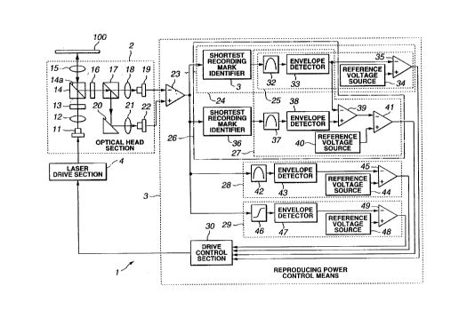
As shown in FIG. 4, a magneto-optical disk device 1 comprises an optical
head section 2 which emits a laser beam from a semiconductor laser 11 as a
light
source to record and reproduce data onto and from a magneto-optical disk 100,
a
laser drive section 4 which drives which drives the semiconductor laser 11,
and a
reproducing power control secrion 3 which controls the laser drive section 4,
where
roughly classified. Here, the magneto-optical disk 100 onto and from which
data is
recorded and reproduced by the magneto-optical disk device 1 adopts a filin
structure to which the DWDD reproducing method. This magneto-optical disk 100
is supported and rotated by a magnet chuck or the like not shown.
The optical head section 2 comprises a semiconductor laser 11, a collimator
lens 12, a grating lens 13, a beam splitter 14, an objective lens 15, a 1%2
wavelength
36
CA 02308427 2000-OS-10
plate 16, a deflection beam sputter 17, a convergence lenses 18 and 21, a
deflection
mirror 20, and first and second light receive sections 19 and 22.
In the optical head section 2 having a structure as described above, a laser
beam is emitted from the semiconductor laser 11. Here, the semiconductor laser
11
emits a reproducing laser beam and a recording laser beam by making the output
level differ between recording and reproducing. The output level of this
semiconductor laser 11 is controlled by a drive control section 4.
The laser beam emitted from the semiconductor laser 11 is changed into
parallel light by the collimator lens 12 and is irradiated onto the magneto-
optical
disk 100 through the grating 13, beam splitter 44, and objective lens 15.
The objective lens 14 is driven in the focusing direction and the tracking
direction by an actuator not shown, and the laser beam is converged so as to
form a
focus on a desired track on the magneto-optical disk 100 by the objective lens
14
thus driven. The grating 13 functions to divide the beam to obtain a tracking
error
signal used for tacking control.
a The laser beam converged on the magneto-optical disk 100 as described
above is let enter, as reflection light, into the beam sputter through the
objective
lens 15.
The light path of the reflection ught which is thus let enter into the beam
splitter 14 is changed at a reflection surface 14a and is guided toward the
1/2
wavelength plate 16.
37
CA 02308427 2000-OS-10
The 1/2 wavelength plate 16 and the deflection beam splitter 1'~ provided
behind the plate 16 functions to separate and detect a change of the
deflection light
corresponding to magnetization of the magneto-optical disk 100. The reflection
light is split into light fluxes traveling toward the convergence lens 18 and
the
deflection mirror 20 by the 1/2 wavelength plate 16 and the deflection beam
splitter
21.
The light flux split and emitted to the side of the convergence lens 18 is
converged by this convergence lens 18 and is received by the first light
receive
section 19. Meanwhile, the light flux split and emitted to the side of the
deflection
lens 20 is reflected toward the convergence lens 21 by the deflection lens 20
and is
received by the second light receive section 21 through the deflection lens
20. For
example, the light receive sections 19 and 22 are photo-detectors.
The light receive sections 19 and 22 output electric signals corresponding to
the amounts of received light, and these electric signals are inputted to the
reproducing power control section 3.
This reproducing power control means 3 is constructed so as to output a
reproducing signal obtained by differentially detecting electric signals from
the
light receive sections 19 and 22 by a differential amplifier 23.
In the reproducing power control means 3, the output signal from the
differential amplifier 23 is processed by a shortest recording mark identifier
31, a
first band pass filter 32, a first envelope detector 33, and a first
comparator 35, in
38
CA 02308427 2000-OS-10
this order, and is then outputted to a drive control section 30. Here, the
first
comparator 35 is inputted with a reference voltage from a first reference
voltage
source 34.
Also, in this reproducing power control means 3, the output signal from the
differential amplifier 23 is processed by a longest recording mark identifier
36, a
second band pass filter 37, a second envelope detector, and second and thud
comparator 39 and 41, in this order, and is then inputted to a drive control
section
30. Here, the second comparator 39 is inputted with the output signal from the
first
envelope detector 33. Further, the thud comparator 39 to which the output
signal
from the first envelope detector 33 is inputted is inputted with a reference
voltage
from a second refercnce voltage source 40.
Also, in the reproducing power control means 3, the output signal from the
differential amplifier 23 is processed by a third band pass filter 42, a third
envelope
detector 43, and a fourth comparator 45, in this order, and is then inputted
to a
drive processing section 30. Here, the fourth comparator 45 is inputted with a
reference voltage from a third reference voltage source 44.
Also, in the reproducing power control means 3, the output signal from the
differential amplifier 23 is processed by a differentiator 46, a fourth
envelope
detector 47, and a fifth comparator 45, in this order, and is then inputted to
the
drive control section 30. Here, the fifth comparator 45 is inputted with a
reference
voltage from a fourth reference voltage source 44.
39
CA 02308427 2000-OS-10
The reproducing power control means 3 constructed as described above
comprises a reproducing power control section which practices the optical
output
adjustment methods as the first to eighth embodiments described above.
That is, a first reproducing power control section 24 is constructed by the
shortest recording mark identifier 31, the first band pass flter 32, the first
envelope
detector 33, the first reference voltage source 34, and the first comparator
35, and
this first reproducing power control section 24 is used as a reproducing power
control section which practices the optical output adjustment method according
to
the first embodiment described previously.
Also, a second reproducing power control section is constructed by the first
band pass filter 32, the first envelope detector 33, the first reference
voltage source
34, and the first cornparator 35, and this second reproducing power control
section
24 is used as a reproducing power control section which practices the optical
output
adjustment method according to the fifth embodiment described previously.
The relationship between the first and second reproducing power control
Sections 24 and 25 is arranged such that the first reproducing power control
section
24 controls the reproducing power, based on the recording mark recorded as
data
on the magneto-optical disk 100, and the second reproducing power control
section
25 controls the reproducing power, based on the reproducing power adjustment
pattern written in the reference area of the magneto-optical disk 100.
Also, a third reproducing power control section 26 is constructed by the
CA 02308427 2000-OS-10
shortest recording mark identifier 31, the longest recording mark identifier
36, the
first and second band pass filters 32 and 37, the first and second envelope
detector
33 and 38, and the second and third comparator 39 and 41, and this third
reproducing power control section 26 is used as a reproducing power control
section which practices the optical output adjustment method according to the
second embodiment described previously.
Also, a fourth reproducing power control section 27 is constructed by the
first and second band pass filters 32 and 37, the first and second envelope
detector
33 and 38, and the second and third comparator 39 and 41, and this fourth
reproducing power control section 27 is used as a reproducing power control
section which practices the optical output adjustment method according to the
sixth
embodiment described previously.
The relationship between the third and fourth reproducing power control
sections 26 and 27 is arranged such that the third reproducing power control
section
26 controls the reproducing power, based on the recording mark recorded as
data
on the magnex~o-optical disk 100, and the fourth reproducing power control
section
27 controls the reproducing power, based on the reproducing power adjustment
pattern written in the reference area of the magneto-optical disk 100.
Also, a fifth reproducing power control section 28 is constructed by the third
band pass filter 42, the third envelope detector 43, the third reference
voltage
source 44, and the fourth comparator 45, and this fifth reproducing power
control
41
CA 02308427 2000-OS-10
section 28 is used as a reproducing power control section which practices the
optical output adjustment method according to the seventh embodiment described
previously.
Also, a sixth reproducing power control section 29 is constructed by the
differentiator 46, the fourth envelope detector 47, the fourth reference
voltage
source 48, and the fifth comparator 49, and this sixth reproducing power
control
section 29 is used as a reproducing power control section which practices the
optical output adjustment methods according to the fourth and eighth
embodiments
described previously.
The drive control section 30 controls the laser drive section 4, based on the
processing results in the reproducing power control sections 24, 25, 26, 27,
28, and
29 constructed as described above. In the following, the first to sixth power
control
sections 24, 25, 26, 27, 28, and 29 will be specifically explained.
With respect to the first reproducing power control section 24, the
reproducing signal from the differential amplifier 23 is inputted to the
shortest
recording mark identifier 31.
The shortest recording mark identifier 31 detects a shortest recording mark
reproducing signal corresponding to the component of the shortest recording
mark
of a reproducing signal outputted from the differential amplifier 23. That is,
the
differential amplifier 23 described above and the shortest recording mark
identifier
31 construct a reproducing signal detector means for detecting a shortest
recording
42
CA 02308427 2000-OS-10
mark reproducing signal corresponding tv the component of the shortest
recording
mark in the reproducing signal obtained by reproducing the magneto-optical
disk
100. The shortest recording mark reproducing signal detected by the shortest
recording mark identifier 31 is outputted to the first band pass filter 32.
The first band pass filter 32 allows a predetermined band of the frequency of
the shortest recording mark reproducing signal to pass. The output of this
first
band pass.filter 32 is inputted to the first envelope detector 33.
The first envelope detector 33 is a signal amplitude level detector means for
detecting the shortest recording mark amplitude level from the shortest
recording
mark reproducing signal. The shortest recording mark reproducing signal
amplitude Level detected by the first envelope detector 33 is inputted to the
first
comparator 35.
The first comparator 35 is a comparator means for comparing the shortest
recording mark amplitude level with a predetermined threshold value.
Specifically,
the first comparator 35 compares the first reference voltage regarded as a
predetermined threshold value outputted from the first reference voltage
source 24
with the shortest recording mark amplitude level detected at the first
envelope
detector 33. The first reference voltage is a threshold value Vl shown in FIG.
1(B).
Note that the output level of the first reference voltage source can be set
variable by
a control section not shown. The level determination result made by the first
cvrnparator 25 is inputted tv the drive control section 30.
43
CA 02308427 2000-OS-10
The drive control section 30 is an optical output control means which
controls the reproducing power such that the shortest recording mark amplitude
level is at the first reference voltage or higher, based on the comparison
result of
the first comparator 35. This drive control section 30 sets the reproducing
power
depending on the laser drive section 4, based on the comparison result
described
above, and the laser drive section 4 supplies a current to the semiconductor
laser 11
such that the reproducing power thus set is attained.
In the first reproducing power control section 24 constructed as described
above, the first reference voltage at which a signal can be reproduced with a
lowered fitter is set in the first reference voltage source 34, and the
reproducing
power is adjusted until the shortest recording mark amplitude level is
determined to
be greater than the first reference voltage by the first comparator 35. Since
the
magneto-optical disk device 1 comprises this first reproducing power control
section 24, the fitter of the reproducing signal can be lowered.
Although the first band pass filter is not always indispensable to the first
reproducing power contaol section 24, S/N of the shortest recording mark
reproducing signal can be improved by making the shortest recording mark
reproducing signal pass through the first band pass filter 32.
Explained next will be the second reproducing power control section 25.
The second reproducing power control section 25 controls the reproducing
power,
based on the reproducing power adjustment repetitive pattern constructed only
by
44
CA 02308427 2000-OS-10
shortest recording marks written on the reference area of the magneto-optical
disk
100.
The second reproducing power control section 25 is constructed as not
including the shortest recording mark identifier 31 of the above-described
first
reproducing power control section 24 at the input stage. This is because the
second
power control section 25 controls the reproducing power, based on the
reproducing
signal of the reproducing power adjustment repetitive pattern written in the
reference area of the magneto-optical disk 100, in contrast to the first
reproducing
power control section 24 which controls the reproducing power, based on the
shortest recording mark reproducing signal detected by the shortest recording
mark
identifier 31.
In the second reproducing power control section 25 thus constructed, the
differential amplifier 23 functions as a reproducing signal detector means
which
detects the power adjustment reproducing signal obtained by reproducing the
reproducing power adjustment repetitive pattern.
Also, the first envelope detector 33 functions as a signal amplitude level
detector means which-detects the amplitude level of the power adjustment
reproducing signal, and the first comparator 35 functions as a comparator
means
which compares the amplitude level detected by the first envelope detector 33
with
the second reference voltage outputted by the reference voltage source 34.
CA 02308427 2000-OS-10
By using the second reproducing power control section 25 as a control
section for the reproducing power, the reproducing power can be rapidly
adjusted
to an optimal level.
To realize the structure of the second reproducing power control section 25
while maintaining the structure of the first power control section 24, the
power
adjustment reproducing signal from the differential amplifier 23 needs to be
inputted directly to the first band pass filter 32. This is enabled, for
example, by
arranging the shortest recording mark identifier 31 to have a switch function.
In
this case, when adjusting the reproducing power by the first reproducing power
control section 24, the switch is turned on thereby to enable identification
of the
shortest recording mark at the shortest recording mark identifier 31. Also,
when
adjusting the reproducing power by the second reproducing power control
section
25, the switch is turned off, so that the power adjustment reproducing signal
from
the differential amplifier 23 is not processed at the shortest recording mark
identifier 31 but is inputted to the band pass filter 32.
FIG. 5 shows a specific example of a magneto-optical disk 100 on which a
reference area is formed. In a normal magneto-optical disk, initial
information of
the disk is provided in a read-in are 100a provided on the inner circumference
or a
read-out area 100b provided on the outer circumference. A reference area where
a
pattern for reproducing power adjustment is recorded can be provided in this
read-
in area 100a or the read-out area 100b. Also, recording of data is normally
carried
46
CA 02308427 2000-OS-10
out in units of sectors or tracks, and address areas where addresses for
specifying
sector positions and track positions are recorded are provided at various
portions on
the magneto-optical disk 100. The magneto-optical disk 100 shown in FIG. 5 is
an
example which is constructed by adopting a CAV (Constant Angular Velocity)
method, and address areas 100c are arranged radially. For example, reference
areas
can be provided adjacent to the address areas 100. In the magneto-optical disk
100
shown in FIG. 5, the hatched area can be considered as reference areas.
Next, explanation will be made of the third reproducing power control
section 26. This third reproducing power control section 26 comprises the
shortest
recording mark identifier 31, the first band pass filter 32, and the first
envelope
detector 32 which construct the first reproducing power control section 24.
Also,
the third reproducing power control section 26 comprises the longest recording
mark identifier 36, the second band pass filter 37, the second envelope
detector 38,
the second and third comparators 39 and 41, and the second reference voltage
source 40. In the third reproducing power control section 26, the respective
components function as follows.
The shortest recording mark identifier 31 together with the differential
amplifier 23 functions as a first reproducing signal detector means for
detecting the
shortest recording mark corresponding to the component of the shortest
recording
mark in the reproducing signal obtained by reproducing the magneto-optical
disk
100. The longest recording mark identifier 36 functions as a second
reproducing
47
CA 02308427 2000-OS-10
signal detector means for detecting the longest recording mark reproducing
signal
corresponding to the component of the longest recording mark as a second
recording mark having a length different from that of the first recording mark
in the
reproducing signal obtained by reproducing the magneto-optical disk 100.
Also, the first envelope detector 33 functions as a first signal amplitude
level
detector means for detecting the shortest recording mark amplitude level. The
second envelope detector functions as a second signal amplitude level detector
for
detecting the longest recording mark amplitude level.
Further the second comparator 39 functions as a difference value calculator
means for calculating the difference value between the shortest recording mark
amplitude level and the longest recording mark amplitude level. The third
comparator 41 functions as a comparator means for comparing the difference
value
obtained by the second comparator 39 with a predetermined threshold value.
In this third reproducing power control section 26, the shortest recording
mark reproducing signal is processed by the shortest recording mark identifier
31,
the first band pass filter 32, and the fist envelope detector 32, and the
longest
recording mark reproducing signal is processed by the longest recording mark
identifier 36, the second band pass filter 37, and the second envelope
detector 38.
That is, in the third reproducing power control section 26, the shortest
recording mark reproducing signal is detected from the reproducing signal from
the
differential amplifier 23 by the longest recording mark identifier 31, and the
first
48
CA 02308427 2000-OS-10
band pass filter 32 allows a predetermined band of the frequency of shortest
recording mark reproducing signal to pass. The shortest recording mark
amplitude
level is then detected by the first envelope detector 33. Further, the
amplitude level
of this longest recording mark reproducing signal is inputted to the second
comparator 39. Meanwhile, in the third reproducing power control section 26,
the
longest recording mark reproducing signal is reproduced from the reproducing
signal from the differential amplifier 23 by the longest recording mark
identifier 36,
and the second band pass filter 37 allows a predetermined band of the
frequency of
the shortest recording mark reproducing signal to pass. The longest recording
mark
amplitude level is then detected by the second envelope detector 38. Further,
the
amplitude level of this longest recording mark reproducing signal is inputted
to the
second comparator 39.
The second comparator 39 which is inputted with the shortest recording
mark amplitude level and the longest recording mark amplitude level outputs a
difference value between the shortest and longest mark amplitude levels, to
the
third comparator 41.
The third comp~rator 41 compares the third reference voltage used as a
predetermined threshold value outputted from the second reference voltage
source
24, with the difference value (difference voltage) of the second comparator
39.
The second reference voltage is a threshold value 0V as shown in FIG. 1(B).
Note
that the output level of the second reference voltage source 40 can be set
variable
49
CA 02308427 2000-OS-10
by a control section not shown. The magnitude determination result by the
third
comparator 41 is inputted to the drive control section 30.
The drive control section 30 sets the reproducing power in the laser drive
section 4, based on the comparison result from the third comparator 41. The
laser
drive section 4 supplies the semiconductor laser 11 with a current such that
the set
reproducing power is obtained.
The third power control section 26 constructed as described above sets the
third reference voltage capable of reproducing a signal with a lowered fitter,
in the
second reference voltage source, and the reproducing power can be adjusted by
the
drive control section 30 until the difference value described above is
increased to
be higher than the third reference voltage by the thud comparator 41. Since
the
magneto-optical disk device 1 comprises this third reproducing power control
section 26, the fitter of the reproducing signal can be lowered.
Explained next will be the fourth power control section 27. The fourth
reproducing power control section 27 controls the reproducing power, based on
the
reproducing power adjustment pattern constructed only by the shortest and
longest
recording marks as first and second marks written in the reference area of the
magneto-optical disk 100. Note that the reproducing power adjustment pattern
may
be or need not be a repetitive pattern.
The fourth reproducing power control section 27 is constructed as not
including the shortest recording mark identifier 3 l and the longest recording
mark
CA 02308427 2000-OS-10
identifier 36 of the above-described third reproducing power control section
26 at
the input stage. This is because the third power control section 26 controls
the
reproducing power, based on the reproducing signal of the reproducing power
adjustment pattern written in the reference area of the magneto-optical disk
100, in
contrast to the third reproducing power control section 27 which controls the
reproducing power, based on the shortest and longest recording mark
reproducing
signals detected by the shortest and longest recording mark identifiers 31 and
36.
In the fourth reproducing power control section 25 thus constructed, the
differential amplifier 23 functions as a reproducing signal detector means
which
detects the shortest recording mark reproducing signal corresponding to the
component of the shortest recording mark and the longest recording mark
reproducing signal corresponding to the component of the longest recording
mark,
in the power adjustment reproducing signal obtained by reproducing the
reproducing power adjustment pattern.
Also, the first and second envelope detectors 33 and 3$ function as signal
amplitude level detector means which detect the shortest and longest recording
mark amplitude levels; and the second comparator 39 functions as a difference
value calculator means for calculating a difference value between the shortest
and
longest recording mark amplitude levels. The third comparator~ 41 functions as
a
comparator means which compares the difference value described above with the
fourth reference voltage outputted by the second reference voltage source 40.
51
CA 02308427 2000-OS-10
By using the fourth reproducing power control section 27 as a control
section for the reproducing power, the reproducing power can be rapidly
adjusted
to an optimal level.
To realize the structure of the fourth reproducing power control section 27
while maintaining the structure of the third power control section 26, the
power
adjustment reproducing signal from the differential amplifier 23 needs to be
inputted directly to the first band pass filter 32. This is enabled, for
example, by
arranging the shortest and longest recording mark identifiers 31 and 36 to
have
switch functions, like the second reproducing power control section 25
described
previously.
Next, explanation will be made of the fifth reproducing power control
section 28. This fifth reproducing power control section 28 is constructed so
as to
control the reproducing power by detecting the high-frequency component from
the
reproducing signal from the magneto-optical disk 100. This fifth reproducing
power control section 28 is constructed in consideration of the point that the
high-
frequency component contained in the reproducing signal can be specified by
the
band pass filter and the reproducing power can be adjusted, based on the high-
frequency component of the reproducing signal.
The fifth reproducing power control section 28 comprises the third band pass
filter 42, the third envelope detector 47, the third reference voltage source
48, and
52
CA 02308427 2000-OS-10
the fourth comparator 45. In this fifth reproducing power control section 28,
the
respective components function as follows.
The third band pass filter 42 functions as a reproducing signal detector
means which detects a high-frequency reproducing signal consisting of a high-
frequency component in the reproducing signal obtained by reproducing the
magneto-optical disk, together with the differential amplifier.
Also, the third envelope detector 43 functions as a signal amplitude level
detector means for detecting the high-frequency amplitude level as the
amplitude
level of the high-frequency reproducing signal.
Further, the fourth comparator 45 functions as a comparator means for
comparing the high-frequency amplitude level with the fifth reference voltage
as a
predetermined threshold value outputted from the third reference voltage
source 44.
In the reproducing power control section 28 constructed in this structure, a
predetermined frequency band of the frequency of the reproducing signal from
the
differential amplifier 23 is allowed to pass by the third band pass filter 42,
and the
high-frequency amplitude level is detected by the thud envelope detector 43.
Further, by the fourth ~cbmparator 45, the high-frequency amplitude level
detected
by the third envelope detector 43 is compared with the fifth reference
voltage.
Here, the fifth reference voltage is a threshold value V2 as shown in FIG.
1(B).
The drive control section 30 sets the reproducing power in the laser drive
section 4, based on the comparison result from the fourth comparator 45. The
laser
53
CA 02308427 2000-OS-10
drive section 4 supplies the semiconductor laser 11 with a current such that
the set
reproducing power is obtained.
The fifth power control section 28 constructed as described above sets the
third reference voltage capable of reproducing a signal with a lowered fitter,
in the
third reference voltage source 44, and the reproducing power is adjusted by
the
drive control section 30 until the difference value described above is
increased to
be higher than the fifth reference voltage by the fourth comparator 45. Since
the
magneto-optical disk device 1 comprises this fifth reproducing power control
section 28, the fitter of the reproducing signal can be lowered.
The fifth power control section 28 can also detect the high-frequency
component of the shortest recording mark reproducing signal corresponding to
the
component of the shortest recording mark in the reproducing signal obtained by
reproducing the magneto-optical disk 100.
Further, the fifth reproducing power control section 28 can adjust the
reproducing power, based on the pattern for power adjustment which is written
in
the reference area of the magneto-optical disk 100. That is, the fifth
reproducing
power control section 28 can adjust the reproducing power, based on a
comparison
result obtained by comparing the amplitude level of the high-frequency
reproducing
signal consisting of a high-frequency component in the power adjustment
reproducing signal obtained by reproducing the power reproducing pattern
written
in the reference area, with the sixth reference voltage outputted by the third
54
CA 02308427 2000-OS-10
reference voltage source 44. Further, in this case, the band of the signal
which is
allowed to pass by the third band pass filter 42 can be limited by
constructing the
reproducing power adjustment pattern written in the reference area, only by
specific marks, i.e., by preparing a repetitive pattern constructed only by
the
shortest marks. S/N can be reduced by thus limiting the signal pass band of
the
third band pass filter 42.
Next, explanation will be made of the sixth reproducing power control
section 29. This sixth reproducing power control section 29 comprises the
differentiator 46, the fourth envelope detector 47, the fourth reference
voltage
source 48; and the fifth comparator 49.
The differentiator 46 together with the differential amplifier 23 constructs a
differentiator means which differentiates the reproducing signal obtained by
reproducing the magneto-optical disk and outputs a differential signal.
The fourth envelope detector 47 functions as a signal amplitude level
detector means which detects the differential signal amplitude level as the
amplitude level of the differential signal.
The fourth co~tiparator 49 functions as a comparator means which compares
the differential amplitude level with the seventh reference voltage used as a
predetermined threshold value outputted from the fourth reference voltage
source
48.
CA 02308427 2000-OS-10
The sixth power control section 29 constructed as described above sets the
seventh reference voltage capable of reproducing a signal with a lowered
fitter, in
the fourth reference voltage source, and the reproducing power is adjusted by
the
drive control section 30 until the differential signal amplitude level is
increased to
be higher than the seventh reference voltage by the fourth comparator 49.
Since the
magneto-optical disk device 1 comprises this sixth reproducing power control
section 29, the fitter of the reproducing signal can be lowered.
Also, the sixth reproducing power control section 29 can adjust the
reproducing power, based on the pattern for power adjustment, which is written
in
the reference area of the magneto-optical disk 100. That is, in this case, the
sixth
reproducing power control section 29 can adjust the reproducing power, based
on a
comparison result obtained by comparing the amplitude level of the
differential
signal obtained by differentiating the power adjustment reproducing signal
obtained
by reproducing the power reproducing pattern written in the reference area,
with
the eighth reference voltage outputted by the third reference voltage source.
The magneto-optical disk device 1 is capable of controlling the reproducing
power to an optimal h'vel, by the reproducing power control means 3 comprising
the first to sixth reproducing power control sections 24, 25, 26, 27, 2$, and
29 as
described above.
In this manner, the magneto-optical disk device 1 can set an optimal
reproducing power which is capable of reproducing a signal excellently even if
56
CA 02308427 2000-OS-10
there are temperature changes and variants between magneto-optical disks in
the
DWDD reproducing method.
The reproducing power control means 3 can make the first to sixth
reproducing power control sections 24, 25, 26, 27, 28, and 29 function singly
or in
combination with each other. Further, in case where the first to sixth
reproducing
power control sections are used in combination, the reproducing power can be
controlled to a more optimal reproducing power by selecting reproducing power
control sections in compliance with the situation.
Also, the magneto-optical disk can comprise a power adjustment pattern
writer means for writing a pattern for reproducing power adjustment. As a
result of
this, the magneto-optical disk device l .can always control the reproducing
power,
based on the pattern for reproducing power adjustment which is written in the
reference area. For example, in this case, the pattern for reproducing power
adjustment is written into the reference area while determining the length
with
which the mark is written and whether or not the pattern is repetitive.
An optical output adjushnent apparatus according to the present invention
comprises: a light source for emitting the reproducing laser beam; reproducing
signal detector means for detecting a shortest recording mark reproducing
signal
corresponding to a component of a shortest recording mark in a reproducing
signal
obtained by reproducing the magneto-optical information recording medium;
signal
amplitude level detector means for detecting an amplitude level of the
shortest
57
CA 02308427 2000-OS-10
recording mark reproducing signal; comparator means for comparing the
amplitude
level with a predetermined threshold value; and optical output control means
for
adjusting the reproducing laser beam to an output level which makes the
amplitude
level equal to or higher than the predetennined threshold value. Therefore,
the
reproducing laser beam can be set to an output level at which a reproducing
signal
with a lowered fitter can be obtained.
Also, in an optical output adjustment method according to the present
invention, based on a comparison result between a predetermined threshold
value
and an amplitude level of a shortest recording mark reproducing signal
corresponding to a component of a shortest recording mark in a reproducing
signal
obtained by reproducing the magneto-optical information recording medium, the
reproducing laser beam is adjusted to an output level which makes the
amplitude
level equal to or higher than the predetermined threshold value. Therefore,
the
reproducing laser beam can be set to an output level at which a reproducing
signal
with a lowered fitter can be obtained.
Also, an optical output adjustment apparatus according to the present
invention comprises: a light source for emitting the reproducing laser beam;
first
reproducing signal detector means for detecting a first recording mark
reproducing
signal corresponding to a component of a first recording mark in a reproducing
signal obtained .by reproducing the magneto-optical information recording
medium;
second reproducing signal detector means for detecting a second recording mark
58
CA 02308427 2000-OS-10
reproducing signal corresponding to a component of a second recording mark in
a
reproducing signal obtained by reproducing the magneto-optical information
recording medium; first signal amplitude level detector means for detecting a
first
amplitude level of the first recording mark reproducing signal; second signal
amplitude level detector means for detecting a second amplitude level of the
second
recording mark reproducing signal; difference value calculator means fox
calculating a difference value between the first and second amplitude levels;
comparator means for comparing the amplitude level with a predetermined
threshold value; and optical output control means for adjusting the
reproducing
laser beam to an output Ievel which makes the amplitude level equal to or
lower
than the predetern~ined threshold value. Therefore, the reproducing laser beam
can
be set to an output level at which a reproducing signal with a lowered fitter
can be
obtained.
.Also, in an optical output adjustment method according to the present
invention, based on a comparison result between a threshold value and a
difference
value between first and second amplitude levels of first and second recording
mark
reproducing signals corresponding to components of first and second recording
marks having lengths different from each other in a reproducing signal
obtained by
reproducing the magneto-optical information recording medium, the reproducing
laser beam is adjusted to an output level which makes the amplitude level
equal to
or lower than the predetermined threshold value. Therefore, the reproducing
laser
59
CA 02308427 2000-OS-10
beam can be set to an output level at which a reproducing signal with a
lowered
fitter can-be obtained.
Also, an optical output adjustment apparatus according to the present
invention comprises: a light source for emitting the reproducing laser beam;
reproducing signal detector means for detecting a high-frequency reproducing
signal consisting of a high-frequency component in a reproducing signal
obtained
by reproducing the magneto-optical information recording medium; signal
amplitude level detector means for detecting an amplitude level of the high-
frequency reproducing signal; comparator means for comparing the amplitude
level
with a predetermined threshold value; and optical output control means for
adjusting the reproducing laser beam to an output level which makes the
amplitude
level equal to or higher than the predetermined threshold value. Therefore,
the
reproducing laser beam can be set to an output level at which a reproducing
signal
with a lowered fitter can be obtained.
Also, in an optical output adjustment method according to the present
invention, based on a comparison result between a predetermined threshold
value
and an amplitude level of a high-frequency reproducing signal of a high-
frequency
component in a reproducing signal obtained by reproducing the magneto-optical
information recording medium, the reproducing laser beam is adjusted to an
output '
level which makes the amplitude level equal to or higher than the
predetermined
CA 02308427 2000-OS-10
threshold value. Therefore, the reproducing laser beam can be set to an output
level at which a reproducing signal with a lowered fitter can be obtained.
Also, an optical output adjustment apparatus according to the present
invention comprises: a light source for emitting the reproducing laser beam;
differentiator means for differentiating a reproducing signal obtained by
reproducing the magneto-optical information recording medium, thereby to
output
a differential signal; signal amplitude level detector means for detecting an
amplitude level of the differential signal; comparator means for comparing the
amplitude level with a predetermined threshold value; and optical output
control
means for adjusting the reproducing laser beam to an output level which makes
the
amplitude level equal to or higher than the predetermined threshold value.
Therefore, the reproducing laser beam can be set to an output level at which a
reproducing signal with a lowered fitter can be obtained.
Also, in an optical output adjustment method according to the present
invention, based on a comparison result between a predetermined threshold
value
and an amplitude level of a differential signal obtained by differentiating a
reproducing signal obtained by reproducing the magneto-optical information
recording medium, the reproducing laser beam is adjusted to an output level
which
makes the amplitude level cqual to or higher than the predetermined threshold
value. Therefore, the reproducing laser beam can be set to an output level at
which
a reproducing signal with a lowered fitter can be obtained.
61
CA 02308427 2000-OS-10
Also, an optical output adjustment apparatus according to the present
invention comprises: a light source for emitting the reproducing laser beam;
reproducing signal detector means for detecting a power adjustment reproducing
signal obtained by reproducing the reproducing power adjustment repetitive
pattern; signal amplitude level detector means for detecting an amplitude
level of
the power adjustment reproducing signal; comparator means for comparing the
amplitude level with a predetermined threshold value; and optical output
control
means for adjusting the reproducing laser beam to an output level which makes
the
amplitude level equal to or higher than the predetermined threshold value.
Therefore, the reproducing laser beam can be set to an output level at which a
reproducing signal with a lowered fitter can be obtained.
Also, in an optical output adjustment method according to the present
invention, based on a comparison result between a predetermined threshold
value
and an amplitude level of a power adjustment reproducing signal obtained by
reproducing the reproducing power adjustment repetitive pattern, the
reproducing
laser beam is adjusted to an output level w~i,ch makes the amplitude level
equal to
or higher than the predetermined threshold value. Therefore, the reproducing
laser
beam can be set to an output level at which a reproducing signal with a
lowered
fitter can be obtained.
Also, an optical output adjustment apparatus according to the present
invention comprises: a light source for emitting the reproducing laser beam;
first
62
CA 02308427 2000-OS-10
reproducing signal detector means for detecting a first mark reproducing
signal
corresponding to a component of the first mark in a power adjustment
reproducing
signal obtained by reproducing the reproducing power adjustment pattern;
second
reproducing signal detector means for detecting a second mark reproducing
signal
corresponding to a component of the second mark in a power adjustment
reproducing signal obtained by reproducing the reproducing power adjustment
pattern; first signal amplitude level detector means for detecting an
amplitude level
of the first mark reproducing signal; second signal amplitude level detector
means
for detecting an amplitude level of the second mark reproducing signal;
difference
value calculator means for calculating a difference value between the first
and
second amplitude levels; comparator means for comparing the difference value
with a predetermined threshold value; and optical output control means for
adjusting the reproducing laser beam to an output level which makes the
amplitude
level equal to or lower than the predetermined threshold value. Therefore, the
reproducing laser beam can be set to an output level at which a reproducing
signal
with a lowered fitter can be obtained.
Also, in an optical output adjustment method according to the present
invention, based on a comparison result between a predetermined threshold
value
and a difference value between first and second amplitude levels of first and
second
mark reproducing signals corresponding to components of the first and second
marks obtained by reproducing the reproducing power adjustment pattern.
63
CA 02308427 2000-OS-10
Therefore, the reproducing laser beam can be set to an output level at which a
reproducing signal with a lowered fitter can be obtained.
Also, an optical output adjusrinent apparatus according to the present
invention comprises: a light source for emitting the reproducing laser beam;
reproducing signal detector means for detecting a high-frequency component in
a
power adjustment reproducing signal obtained by reproducing the reproducing
power adjustment repetitive pattern; signal amplitude level detector means for
detecting an amplitude level of the high-frequency reproducing signal;
comparator
means for comparing the amplitude level with a predetermined threshold value;
and
optical output control means for adjusting the reproducing laser beam to an
output
level which makes the amplitude level equal to or higher than the
predetermined
threshold value. Therefore, the reproducing laser beam can be set to an output
level at which a reproducing signal with a lowered fitter can be obtained.
Also, in an optical output adjustment method according to the present
invention, based on a comparison result between a predetermined threshold
value
and an amplitude level of a high-frequency reproducing signal consisting of a
high-
frequency component in a power adjustment reproducing signal obtained by
reproducing the reproducing power adjustment repetitive pattern, the
reproducing
laser beam is adjusted to an output level which makes the amplitude level
equal to
or higher than the predetermined threshold value. Therefore, the reproducing
laser
64
CA 02308427 2000-OS-10
beam can be set to an output level at which a reproducing signal with a
lowered
fitter can be obtained.
Also, an optical output adjustment apparatus according to the present
invention comprises: a light source for emitting the reproducing laser beam;
differentiator means for differentiating a power adjustment reproducing signal
obtained by reproducing the reproducing power adjustment pattern, thereby to
output a differential signal; signal amplitude level detector means for
detecting an
amplitude level of the differential signal; comparator means for comparing the
amplitude level with a predetermined threshold value; and optical output
control
means for adjusting the reproducing laser beam to an output level which makes
the
amplitude level equal to or higher than the predetermined threshold value.
Also, in an optical output adjustment method according to the present
invention, based on a comparison result between a predetermined threshold
value
and an amplitude level of a differential signal obtained by differentiating a
power
adjustment reproducing signal obtained by reproducing the reproducing power
adjustment pattern, the reproducing laser beam is adjusted to an output level
which
makes the amplitude-ievel equal to or higher than the predetermined threshold
value. Therefore, the reproducing laser beam can be set to an output level at
which
a reproducing signal with a lowered fitter can be obtained.