Language selection

Search

Patent 2308469 Summary

Third-party information liability

Some of the information on this Web page has been provided by external sources. The Government of Canada is not responsible for the accuracy, reliability or currency of the information supplied by external sources. Users wishing to rely upon this information should consult directly with the source of the information. Content provided by external sources is not subject to official languages, privacy and accessibility requirements.

Claims and Abstract availability

Any discrepancies in the text and image of the Claims and Abstract are due to differing posting times. Text of the Claims and Abstract are posted:

  • At the time the application is open to public inspection;
  • At the time of issue of the patent (grant).
(12) Patent: (11) CA 2308469
(54) English Title: REFRACTORY NOZZLE
(54) French Title: BUSE REFRACTAIRE
Status: Expired and beyond the Period of Reversal
Bibliographic Data
(51) International Patent Classification (IPC):
  • B22D 41/50 (2006.01)
  • B22D 41/08 (2006.01)
  • B22D 41/40 (2006.01)
(72) Inventors :
  • MILLS, STEPHEN DAVID (United Kingdom)
(73) Owners :
  • STEPHEN DAVID MILLS
(71) Applicants :
  • STEPHEN DAVID MILLS (United Kingdom)
(74) Agent: SMART & BIGGAR LP
(74) Associate agent:
(45) Issued: 2010-04-13
(86) PCT Filing Date: 1999-09-01
(87) Open to Public Inspection: 2000-03-16
Examination requested: 2004-08-04
Availability of licence: N/A
Dedicated to the Public: N/A
(25) Language of filing: English

Patent Cooperation Treaty (PCT): Yes
(86) PCT Filing Number: PCT/GB1999/002877
(87) International Publication Number: WO 2000013822
(85) National Entry: 2000-05-03

(30) Application Priority Data:
Application No. Country/Territory Date
9819191.9 (United Kingdom) 1998-09-04

Abstracts

English Abstract


A refractory nozzle comprises upper and
lower members (20 and 22) having matching
tapered bores. The members fit together so
that the bores match, and are secured in the
hole (16) in the bottom of a metallurgical
vessel by a retaining plate (66) and a bottom
plate (86). The bottom plate (86) can be
removed to allow the lower member (22) to be
replaced without disturbing the upper member.


French Abstract

Cette buse réfractaire est constituée d'un élément supérieur (20) et d'un élément inférieur (22) présentant des perçages coniques complémentaires. Ces éléments, qui s'adaptent l'un sur l'autre de façon que les perçages coïncident, sont bloqués dans le trou (16) du fond du récipient métallurgique par une platine de retenue (66) et une platine de fond (86). Cette platine de fond (86) peut être déposée de façon à permettre le remplacement de l'élément inférieur (22) sans avoir à intervenir sur l'élément supérieur.

Claims

Note: Claims are shown in the official language in which they were submitted.

-8-
CLAIMS:
1. A refractory nozzle comprising upper and lower members, the upper
member having an axial passage comprising a mouth at the top end of the
passage, a first tapered bore, and an enlarged diameter section at the
bottom end of the passage, and the lower member having a second tapered
bore the top end of which matches the bottom of the first tapered bore of the
upper member and a top fitting into the enlarged section.
2. The nozzle as claimed in claim 1, in which a gasket is located between
the top end surface of the lower member and the upper member in the
enlarged section of the first tapered bore of the upper member.
3. The nozzle as claimed in claim 1 or claim 2, in which the outer surface
of the upper member tapers out from top to bottom.
4. The nozzle as claimed in any one of claims 1 to 3, in which the lower
member has an external shoulder at its lower end.
5. A bottom pour metallurgical vessel having a hole in its bottom, a
nozzle as claimed in any one of claims 1 to 4 and means for securing the
nozzle in position in the hole.
6. The vessel as claimed in claim 5, in which said means comprises a
retaining plate secured to the bottom of a ladle and engaging the bottom of
the upper member.
7. The vessel as claimed in claim 6, in which said means includes a
bottom plate secured to the retaining plate and engaging the lower member,
the distance between the plates being adjustable so that the lower member
can be forced into sealing engagement with the upper member.

-9-
8. The vessel as claimed in claim 7, in which the bottom plate is secured
to the retaining plate by shielded bolts.
9. The vessel as claimed in claim 7 or claim 8, in which the lower
member has an external shoulder at its lower end, and in which the bottom
plate engages the external shoulder on the lower member.

Description

Note: Descriptions are shown in the official language in which they were submitted.


CA 02308469 2000-05-03
WO 00/13822 PCT/GB99/02877
-1-
REFRACTORY NOZZLE
This invention relates to a refractory nozzle for use with
a metallurgical vessel such as a bottom pour ladle or a casting
box.
In foundries devices such as bottom pour ladles, casting
boxes and the like are used extensively to pour molten metal
into moulds; these devices, which will hereinafter be referred
to simply as ladles are provided with a refractory nozzle in
their bottom. The flow of molten metal through the nozzle is
controlled by a refractory stopper in the interior of the
ladle, the stopper being moved into and out of the nozzle
aperture.
For a given mould, there is a correct nozzle outlet
diameter and only a small range of suitable flow rates of metal
into the mould as too great a flow rate can damage the mould
while too slow a flow rate results in an unsatisfactory
casting. The maximum rate of flow of the metal through the
nozzle is determined by the outlet diameter of the nozzle and
the depth or ferrostatic head of metal in the ladle, and
lessens as the head of metal decreases. Thus problems can
arise when, as is common, a number of different moulds have to
be poured from a single ladle as if the flow rate is
appropriate for the first mould then it is too small for later
moulds.
A commonly adopted solution to this problem is to use a

CA 02308469 2000-05-03
WO 00/13822 PCT/GB99/02877
-2-
nozzle that is oversize for the initial pourings and to
control the flow by means of the stopper. This practice is
not entirely satisfactory as the use of oversize nozzles
tends to produce unsatisfactory castings as does undue
throttling of the metal flow by the stopper.
It is an object of the present invention to obviate or
mitigate these problems.
The present invention is refractory nozzle comprising
upper and lower members, the upper member having an axial
passage comprising a mouth at its top end, a tapered bore, and
an enlarged diameter section at its bottom end, and the lower
member having a top fitting into the enlarged section, and a
tapered bore the top end of which matches the bottom of the
tapered bore of the upper member.
The present invention is also a bottom pour metallurgical
vessel having a hole in its bottom, a nozzle as defined in the
last preceding paragraph and means for securing the nozzle in
position in the hole.
An embodiment of the present invention will now be
described, by way of example, with reference to the
accompanying drawings in which:-
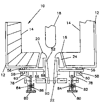
Fig. 1 is a cross-sectional view through the bottom of a
bottom pour ladle having a refractory nozzle
according to the present invention;

CA 02308469 2000-05-03
WO 00/13822 PCT/GB99/02877
-3-
Figs 2 and 3 are respectively a cross-sectional elevation
and a perspective view of an upper refractory member
used in the nozzle of Fig. 1; and
Figs. 4 and 5 are respectively a cross-sectional elevation
and a perspective view of a lower refractory member
used in the nozzle of Fig. 1.
Referring now to Fig. 1, a metallurgical vessel, in this
embodiment a bottom pour ladle 10, comprises an outer steel
shell 12 with a lining 14 of a refractory material. In the
bottom of the ladle is provided a hole 16 through both the
lining 14 and the shell 12, the hole 16 increasing in diameter
as it passes from the inside of the lining 14 to the outside
of the shell 12. The hole 16 is provided to locate a nozzle
through which the contents of the ladle 10 can be discharged.
Associated with the ladle is a refractory stopper 18. The
ladle 10, as so far described, is essentially a standard item.
In this embodiment of the present invention, the discharge
nozzle comprises upper and lower refractory members 20 and 22
as shown in Figs. 2 and 3 and Figs 4 and 5 respectively. The
upper refractory member 20 has an axial length that is greater
than the length of the hole 16, and an external surface 24
which increases in diameter from top to bottom to match the
surface of the hole 16. As seen best in Fig. 2, the member 20
has an axial passage having three sections, namely a mouth 30,
a tapered bore 32, and a section 34 of constant diameter.
The mouth 30 acts as a seating area for the stopper 18 and

CA 02308469 2000-05-03
WO 00/13822 PCT/GB99/02877
-4-
is shaped to provide a smooth transition from the transverse
upper end face 36 of the member 20 to the tapered bore 32.
The section 34 has a diameter greater than that of the
bottom end of the bore 32 and the transition between the two
is an annular surface 38. At the bottom of the member 20 is
an annular end surface 39.
The lower refractory member 22 has a stepped outer surface
in two sections, an upper section 40 of uniform diameter and,
at the bottom, a small section 42 of a smaller diameter, the
transition between the two sections again being an annular
surface or shoulder 44. The member 22 has a tapered bore 46,
an upper annular end surface 48, and a lower annular end
surface 50.
As seen in Fig. 1, the two refractory members 20 and 22
fit together in the hole 16, the outer surface 24 of the upper
member engaging the surface of the hole 16 and the lower member
22 fitting into the constant diameter section 34 of the upper
member. A gasket 52 is located between the upper end surface
48 of the lower member 22 and the annular surface 38 of the
upper member 20. The tapered bores in the two members are then
loined without any transition that would disturb the smooth
flow of metal.
On the bottom of the ladle 10 are provided three pillers
56 in a triangular configuration, each of the pillers 56 being
rectangular in cross-section and having a slot 58 passing
through it, the slots being elongated in the vertical

CA 02308469 2000-05-03
WO 00/13822 PCT/GB99/02877
-5-
direction. In this embodiment, the surface 60 at the bottom
of each slot 56 is inclined across the slot to provide a
ramp surf ace .
A retaining plate 66 extends across the bottom of the
ladle and has three holes allowing the three pillers 56 to pass
through the plate 66. The plate 66 also has a central hole 68
whose diameter is intermediate that of the outer surfaces of
the members 22 and 24 so that the member 24 can pass freely
through the hole 68 while an annular area around the periphery
of the hole 68 engages the bottom end surface 39 of the upper
member 20.
Associated with the retaining plate are wedges (not
illustrated) which pass into the slots 58 on the underside of
the retaining plate 66 and cooperate with the ramp surfaces 60
to force the upper member 20 securely into position in the hole
16.
The retaining plate 66 is further provided on its bottom
surface with a number, in this embodiment two, tapped bosses
78 which engage bolts 80. Between the bottom of the each boss
78 and the head of its associated bolt 80 is a spring 82
surrounded by a shield 84 which acts to protect the thread of
the bolt from splatter.
A bottom plate 86 has two countersunk holes, each allowing
the shank of a bolt to pass through, but not the spring 82, the
shield 84, or the head of the bolt. The heads of the bolts

CA 02308469 2000-05-03
WO 00/13822 PCT/GB99/02877
-6-
compress the springs against the bottom surface of the plate
86 to retain the plate in position. A central hole 90 in
the plate 86 has a diameter intermediate the diameters of
the portions 40 and 42 of the lower member 22 so that the
end surface 50 of the member 42 is engaged by an annular
area surrounding the hole 90.
In use, as the bolts 80 are tightened, the gasket 90 is
compressed between the lower and upper members to seal the
junction between them. The gasket also ensures that the
members do not stick together.
This arrangement allows the lower member 22 to be changed
for another member 22 having a larger or smaller exit aperture
and therefore a different flow rate. It is to be understood
that the taper of the bore of the lower member is always the
same as the taper of the bore of the upper member, different
exit apertures being achieved by varying the length of the
lower member. As the lower member 22 fits into the upper
member 20 problems of clearance over static moulds are largely
avoided.
It has been found that with a tapered bore through both
the upper and lower members the flow rate is less affected by
changes in the ferrostatic head, and that the nozzle bore is
self cleaning. Other major advantages of the nozzle of the
present invention are that the upper and lower members can be
made of different materials to suit better their respective
operating conditions, and the common problem of deposits on the

CA 02308469 2000-05-03
WO 00/13822 PCT/GB99/02877
-7-
lower part of the nozzle can be avoided simply by replacing
as necessary the lower member 22.
The springs 82 compensate for heat expansion of the bolts,
and the shields 84 protect the bolt threads from contamination.

Representative Drawing
A single figure which represents the drawing illustrating the invention.
Administrative Status

2024-08-01:As part of the Next Generation Patents (NGP) transition, the Canadian Patents Database (CPD) now contains a more detailed Event History, which replicates the Event Log of our new back-office solution.

Please note that "Inactive:" events refers to events no longer in use in our new back-office solution.

For a clearer understanding of the status of the application/patent presented on this page, the site Disclaimer , as well as the definitions for Patent , Event History , Maintenance Fee  and Payment History  should be consulted.

Event History

Description Date
Time Limit for Reversal Expired 2018-09-04
Change of Address or Method of Correspondence Request Received 2018-01-12
Letter Sent 2017-09-01
Grant by Issuance 2010-04-13
Inactive: Cover page published 2010-04-12
Inactive: Final fee received 2010-01-28
Pre-grant 2010-01-28
Notice of Allowance is Issued 2009-08-25
Letter Sent 2009-08-25
Notice of Allowance is Issued 2009-08-25
Inactive: Approved for allowance (AFA) 2009-07-29
Amendment Received - Voluntary Amendment 2009-03-26
Inactive: S.30(2) Rules - Examiner requisition 2008-12-16
Amendment Received - Voluntary Amendment 2008-05-13
Inactive: S.30(2) Rules - Examiner requisition 2008-04-10
Letter Sent 2004-08-24
Request for Examination Received 2004-08-04
Request for Examination Requirements Determined Compliant 2004-08-04
All Requirements for Examination Determined Compliant 2004-08-04
Inactive: Cover page published 2000-07-04
Inactive: First IPC assigned 2000-06-25
Inactive: Notice - National entry - No RFE 2000-06-21
Inactive: Inventor deleted 2000-06-19
Application Received - PCT 2000-06-16
Application Published (Open to Public Inspection) 2000-03-16

Abandonment History

There is no abandonment history.

Maintenance Fee

The last payment was received on 2009-08-17

Note : If the full payment has not been received on or before the date indicated, a further fee may be required which may be one of the following

  • the reinstatement fee;
  • the late payment fee; or
  • additional fee to reverse deemed expiry.

Please refer to the CIPO Patent Fees web page to see all current fee amounts.

Owners on Record

Note: Records showing the ownership history in alphabetical order.

Current Owners on Record
STEPHEN DAVID MILLS
Past Owners on Record
None
Past Owners that do not appear in the "Owners on Record" listing will appear in other documentation within the application.
Documents

To view selected files, please enter reCAPTCHA code :


To view images, click a link in the Document Description column. To download the documents, select one or more checkboxes in the first column and then click the "Download Selected in PDF format (Zip Archive)" or the "Download Selected as Single PDF" button.

List of published and non-published patent-specific documents on the CPD .

If you have any difficulty accessing content, you can call the Client Service Centre at 1-866-997-1936 or send them an e-mail at CIPO Client Service Centre.


Document
Description 
Date
(yyyy-mm-dd) 
Number of pages   Size of Image (KB) 
Representative drawing 2000-07-04 1 10
Abstract 2000-05-03 1 50
Description 2000-05-03 7 249
Claims 2000-05-03 2 50
Drawings 2000-05-03 2 44
Cover Page 2000-07-04 1 39
Claims 2008-05-09 2 43
Claims 2009-03-26 2 45
Representative drawing 2010-03-16 1 11
Cover Page 2010-03-16 1 38
Notice of National Entry 2000-06-21 1 192
Reminder of maintenance fee due 2001-05-02 1 111
Reminder - Request for Examination 2004-05-04 1 116
Acknowledgement of Request for Examination 2004-08-24 1 177
Commissioner's Notice - Application Found Allowable 2009-08-25 1 162
Maintenance Fee Notice 2017-10-13 1 181
PCT 2000-05-03 4 140
Fees 2003-08-11 1 30
Fees 2001-08-20 1 31
Fees 2002-08-09 1 32
Fees 2004-08-06 1 38
Fees 2005-08-15 1 23
Fees 2006-08-10 1 28
Fees 2007-08-14 1 28
Fees 2008-08-11 1 34
Fees 2009-08-17 1 34
Correspondence 2010-01-28 1 34
Fees 2010-06-28 1 34