Sélection de la langue

Search

Sommaire du brevet 2308469 

Énoncé de désistement de responsabilité concernant l'information provenant de tiers

Une partie des informations de ce site Web a été fournie par des sources externes. Le gouvernement du Canada n'assume aucune responsabilité concernant la précision, l'actualité ou la fiabilité des informations fournies par les sources externes. Les utilisateurs qui désirent employer cette information devraient consulter directement la source des informations. Le contenu fourni par les sources externes n'est pas assujetti aux exigences sur les langues officielles, la protection des renseignements personnels et l'accessibilité.

Disponibilité de l'Abrégé et des Revendications

L'apparition de différences dans le texte et l'image des Revendications et de l'Abrégé dépend du moment auquel le document est publié. Les textes des Revendications et de l'Abrégé sont affichés :

  • lorsque la demande peut être examinée par le public;
  • lorsque le brevet est émis (délivrance).
(12) Brevet: (11) CA 2308469
(54) Titre français: BUSE REFRACTAIRE
(54) Titre anglais: REFRACTORY NOZZLE
Statut: Périmé et au-delà du délai pour l’annulation
Données bibliographiques
(51) Classification internationale des brevets (CIB):
  • B22D 41/50 (2006.01)
  • B22D 41/08 (2006.01)
  • B22D 41/40 (2006.01)
(72) Inventeurs :
  • MILLS, STEPHEN DAVID (Royaume-Uni)
(73) Titulaires :
  • STEPHEN DAVID MILLS
(71) Demandeurs :
  • STEPHEN DAVID MILLS (Royaume-Uni)
(74) Agent: SMART & BIGGAR LP
(74) Co-agent:
(45) Délivré: 2010-04-13
(86) Date de dépôt PCT: 1999-09-01
(87) Mise à la disponibilité du public: 2000-03-16
Requête d'examen: 2004-08-04
Licence disponible: S.O.
Cédé au domaine public: S.O.
(25) Langue des documents déposés: Anglais

Traité de coopération en matière de brevets (PCT): Oui
(86) Numéro de la demande PCT: PCT/GB1999/002877
(87) Numéro de publication internationale PCT: WO 2000013822
(85) Entrée nationale: 2000-05-03

(30) Données de priorité de la demande:
Numéro de la demande Pays / territoire Date
9819191.9 (Royaume-Uni) 1998-09-04

Abrégés

Abrégé français

Cette buse réfractaire est constituée d'un élément supérieur (20) et d'un élément inférieur (22) présentant des perçages coniques complémentaires. Ces éléments, qui s'adaptent l'un sur l'autre de façon que les perçages coïncident, sont bloqués dans le trou (16) du fond du récipient métallurgique par une platine de retenue (66) et une platine de fond (86). Cette platine de fond (86) peut être déposée de façon à permettre le remplacement de l'élément inférieur (22) sans avoir à intervenir sur l'élément supérieur.


Abrégé anglais


A refractory nozzle comprises upper and
lower members (20 and 22) having matching
tapered bores. The members fit together so
that the bores match, and are secured in the
hole (16) in the bottom of a metallurgical
vessel by a retaining plate (66) and a bottom
plate (86). The bottom plate (86) can be
removed to allow the lower member (22) to be
replaced without disturbing the upper member.

Revendications

Note : Les revendications sont présentées dans la langue officielle dans laquelle elles ont été soumises.


-8-
CLAIMS:
1. A refractory nozzle comprising upper and lower members, the upper
member having an axial passage comprising a mouth at the top end of the
passage, a first tapered bore, and an enlarged diameter section at the
bottom end of the passage, and the lower member having a second tapered
bore the top end of which matches the bottom of the first tapered bore of the
upper member and a top fitting into the enlarged section.
2. The nozzle as claimed in claim 1, in which a gasket is located between
the top end surface of the lower member and the upper member in the
enlarged section of the first tapered bore of the upper member.
3. The nozzle as claimed in claim 1 or claim 2, in which the outer surface
of the upper member tapers out from top to bottom.
4. The nozzle as claimed in any one of claims 1 to 3, in which the lower
member has an external shoulder at its lower end.
5. A bottom pour metallurgical vessel having a hole in its bottom, a
nozzle as claimed in any one of claims 1 to 4 and means for securing the
nozzle in position in the hole.
6. The vessel as claimed in claim 5, in which said means comprises a
retaining plate secured to the bottom of a ladle and engaging the bottom of
the upper member.
7. The vessel as claimed in claim 6, in which said means includes a
bottom plate secured to the retaining plate and engaging the lower member,
the distance between the plates being adjustable so that the lower member
can be forced into sealing engagement with the upper member.

-9-
8. The vessel as claimed in claim 7, in which the bottom plate is secured
to the retaining plate by shielded bolts.
9. The vessel as claimed in claim 7 or claim 8, in which the lower
member has an external shoulder at its lower end, and in which the bottom
plate engages the external shoulder on the lower member.

Description

Note : Les descriptions sont présentées dans la langue officielle dans laquelle elles ont été soumises.

CA 02308469 2000-05-03
WO 00/13822 PCT/GB99/02877
-1-
REFRACTORY NOZZLE
This invention relates to a refractory nozzle for use with
a metallurgical vessel such as a bottom pour ladle or a casting
box.
In foundries devices such as bottom pour ladles, casting
boxes and the like are used extensively to pour molten metal
into moulds; these devices, which will hereinafter be referred
to simply as ladles are provided with a refractory nozzle in
their bottom. The flow of molten metal through the nozzle is
controlled by a refractory stopper in the interior of the
ladle, the stopper being moved into and out of the nozzle
aperture.
For a given mould, there is a correct nozzle outlet
diameter and only a small range of suitable flow rates of metal
into the mould as too great a flow rate can damage the mould
while too slow a flow rate results in an unsatisfactory
casting. The maximum rate of flow of the metal through the
nozzle is determined by the outlet diameter of the nozzle and
the depth or ferrostatic head of metal in the ladle, and
lessens as the head of metal decreases. Thus problems can
arise when, as is common, a number of different moulds have to
be poured from a single ladle as if the flow rate is
appropriate for the first mould then it is too small for later
moulds.
A commonly adopted solution to this problem is to use a

CA 02308469 2000-05-03
WO 00/13822 PCT/GB99/02877
-2-
nozzle that is oversize for the initial pourings and to
control the flow by means of the stopper. This practice is
not entirely satisfactory as the use of oversize nozzles
tends to produce unsatisfactory castings as does undue
throttling of the metal flow by the stopper.
It is an object of the present invention to obviate or
mitigate these problems.
The present invention is refractory nozzle comprising
upper and lower members, the upper member having an axial
passage comprising a mouth at its top end, a tapered bore, and
an enlarged diameter section at its bottom end, and the lower
member having a top fitting into the enlarged section, and a
tapered bore the top end of which matches the bottom of the
tapered bore of the upper member.
The present invention is also a bottom pour metallurgical
vessel having a hole in its bottom, a nozzle as defined in the
last preceding paragraph and means for securing the nozzle in
position in the hole.
An embodiment of the present invention will now be
described, by way of example, with reference to the
accompanying drawings in which:-
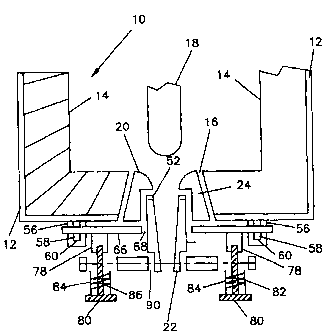
Fig. 1 is a cross-sectional view through the bottom of a
bottom pour ladle having a refractory nozzle
according to the present invention;

CA 02308469 2000-05-03
WO 00/13822 PCT/GB99/02877
-3-
Figs 2 and 3 are respectively a cross-sectional elevation
and a perspective view of an upper refractory member
used in the nozzle of Fig. 1; and
Figs. 4 and 5 are respectively a cross-sectional elevation
and a perspective view of a lower refractory member
used in the nozzle of Fig. 1.
Referring now to Fig. 1, a metallurgical vessel, in this
embodiment a bottom pour ladle 10, comprises an outer steel
shell 12 with a lining 14 of a refractory material. In the
bottom of the ladle is provided a hole 16 through both the
lining 14 and the shell 12, the hole 16 increasing in diameter
as it passes from the inside of the lining 14 to the outside
of the shell 12. The hole 16 is provided to locate a nozzle
through which the contents of the ladle 10 can be discharged.
Associated with the ladle is a refractory stopper 18. The
ladle 10, as so far described, is essentially a standard item.
In this embodiment of the present invention, the discharge
nozzle comprises upper and lower refractory members 20 and 22
as shown in Figs. 2 and 3 and Figs 4 and 5 respectively. The
upper refractory member 20 has an axial length that is greater
than the length of the hole 16, and an external surface 24
which increases in diameter from top to bottom to match the
surface of the hole 16. As seen best in Fig. 2, the member 20
has an axial passage having three sections, namely a mouth 30,
a tapered bore 32, and a section 34 of constant diameter.
The mouth 30 acts as a seating area for the stopper 18 and

CA 02308469 2000-05-03
WO 00/13822 PCT/GB99/02877
-4-
is shaped to provide a smooth transition from the transverse
upper end face 36 of the member 20 to the tapered bore 32.
The section 34 has a diameter greater than that of the
bottom end of the bore 32 and the transition between the two
is an annular surface 38. At the bottom of the member 20 is
an annular end surface 39.
The lower refractory member 22 has a stepped outer surface
in two sections, an upper section 40 of uniform diameter and,
at the bottom, a small section 42 of a smaller diameter, the
transition between the two sections again being an annular
surface or shoulder 44. The member 22 has a tapered bore 46,
an upper annular end surface 48, and a lower annular end
surface 50.
As seen in Fig. 1, the two refractory members 20 and 22
fit together in the hole 16, the outer surface 24 of the upper
member engaging the surface of the hole 16 and the lower member
22 fitting into the constant diameter section 34 of the upper
member. A gasket 52 is located between the upper end surface
48 of the lower member 22 and the annular surface 38 of the
upper member 20. The tapered bores in the two members are then
loined without any transition that would disturb the smooth
flow of metal.
On the bottom of the ladle 10 are provided three pillers
56 in a triangular configuration, each of the pillers 56 being
rectangular in cross-section and having a slot 58 passing
through it, the slots being elongated in the vertical

CA 02308469 2000-05-03
WO 00/13822 PCT/GB99/02877
-5-
direction. In this embodiment, the surface 60 at the bottom
of each slot 56 is inclined across the slot to provide a
ramp surf ace .
A retaining plate 66 extends across the bottom of the
ladle and has three holes allowing the three pillers 56 to pass
through the plate 66. The plate 66 also has a central hole 68
whose diameter is intermediate that of the outer surfaces of
the members 22 and 24 so that the member 24 can pass freely
through the hole 68 while an annular area around the periphery
of the hole 68 engages the bottom end surface 39 of the upper
member 20.
Associated with the retaining plate are wedges (not
illustrated) which pass into the slots 58 on the underside of
the retaining plate 66 and cooperate with the ramp surfaces 60
to force the upper member 20 securely into position in the hole
16.
The retaining plate 66 is further provided on its bottom
surface with a number, in this embodiment two, tapped bosses
78 which engage bolts 80. Between the bottom of the each boss
78 and the head of its associated bolt 80 is a spring 82
surrounded by a shield 84 which acts to protect the thread of
the bolt from splatter.
A bottom plate 86 has two countersunk holes, each allowing
the shank of a bolt to pass through, but not the spring 82, the
shield 84, or the head of the bolt. The heads of the bolts

CA 02308469 2000-05-03
WO 00/13822 PCT/GB99/02877
-6-
compress the springs against the bottom surface of the plate
86 to retain the plate in position. A central hole 90 in
the plate 86 has a diameter intermediate the diameters of
the portions 40 and 42 of the lower member 22 so that the
end surface 50 of the member 42 is engaged by an annular
area surrounding the hole 90.
In use, as the bolts 80 are tightened, the gasket 90 is
compressed between the lower and upper members to seal the
junction between them. The gasket also ensures that the
members do not stick together.
This arrangement allows the lower member 22 to be changed
for another member 22 having a larger or smaller exit aperture
and therefore a different flow rate. It is to be understood
that the taper of the bore of the lower member is always the
same as the taper of the bore of the upper member, different
exit apertures being achieved by varying the length of the
lower member. As the lower member 22 fits into the upper
member 20 problems of clearance over static moulds are largely
avoided.
It has been found that with a tapered bore through both
the upper and lower members the flow rate is less affected by
changes in the ferrostatic head, and that the nozzle bore is
self cleaning. Other major advantages of the nozzle of the
present invention are that the upper and lower members can be
made of different materials to suit better their respective
operating conditions, and the common problem of deposits on the

CA 02308469 2000-05-03
WO 00/13822 PCT/GB99/02877
-7-
lower part of the nozzle can be avoided simply by replacing
as necessary the lower member 22.
The springs 82 compensate for heat expansion of the bolts,
and the shields 84 protect the bolt threads from contamination.

Dessin représentatif
Une figure unique qui représente un dessin illustrant l'invention.
États administratifs

2024-08-01 : Dans le cadre de la transition vers les Brevets de nouvelle génération (BNG), la base de données sur les brevets canadiens (BDBC) contient désormais un Historique d'événement plus détaillé, qui reproduit le Journal des événements de notre nouvelle solution interne.

Veuillez noter que les événements débutant par « Inactive : » se réfèrent à des événements qui ne sont plus utilisés dans notre nouvelle solution interne.

Pour une meilleure compréhension de l'état de la demande ou brevet qui figure sur cette page, la rubrique Mise en garde , et les descriptions de Brevet , Historique d'événement , Taxes périodiques et Historique des paiements devraient être consultées.

Historique d'événement

Description Date
Le délai pour l'annulation est expiré 2018-09-04
Requête pour le changement d'adresse ou de mode de correspondance reçue 2018-01-12
Lettre envoyée 2017-09-01
Accordé par délivrance 2010-04-13
Inactive : Page couverture publiée 2010-04-12
Inactive : Taxe finale reçue 2010-01-28
Préoctroi 2010-01-28
Un avis d'acceptation est envoyé 2009-08-25
Lettre envoyée 2009-08-25
Un avis d'acceptation est envoyé 2009-08-25
Inactive : Approuvée aux fins d'acceptation (AFA) 2009-07-29
Modification reçue - modification volontaire 2009-03-26
Inactive : Dem. de l'examinateur par.30(2) Règles 2008-12-16
Modification reçue - modification volontaire 2008-05-13
Inactive : Dem. de l'examinateur par.30(2) Règles 2008-04-10
Lettre envoyée 2004-08-24
Requête d'examen reçue 2004-08-04
Exigences pour une requête d'examen - jugée conforme 2004-08-04
Toutes les exigences pour l'examen - jugée conforme 2004-08-04
Inactive : Page couverture publiée 2000-07-04
Inactive : CIB en 1re position 2000-06-25
Inactive : Notice - Entrée phase nat. - Pas de RE 2000-06-21
Inactive : Inventeur supprimé 2000-06-19
Demande reçue - PCT 2000-06-16
Demande publiée (accessible au public) 2000-03-16

Historique d'abandonnement

Il n'y a pas d'historique d'abandonnement

Taxes périodiques

Le dernier paiement a été reçu le 2009-08-17

Avis : Si le paiement en totalité n'a pas été reçu au plus tard à la date indiquée, une taxe supplémentaire peut être imposée, soit une des taxes suivantes :

  • taxe de rétablissement ;
  • taxe pour paiement en souffrance ; ou
  • taxe additionnelle pour le renversement d'une péremption réputée.

Veuillez vous référer à la page web des taxes sur les brevets de l'OPIC pour voir tous les montants actuels des taxes.

Titulaires au dossier

Les titulaires actuels et antérieures au dossier sont affichés en ordre alphabétique.

Titulaires actuels au dossier
STEPHEN DAVID MILLS
Titulaires antérieures au dossier
S.O.
Les propriétaires antérieurs qui ne figurent pas dans la liste des « Propriétaires au dossier » apparaîtront dans d'autres documents au dossier.
Documents

Pour visionner les fichiers sélectionnés, entrer le code reCAPTCHA :


Pour visualiser une image, cliquer sur un lien dans la colonne description du document. Pour télécharger l'image (les images), cliquer l'une ou plusieurs cases à cocher dans la première colonne et ensuite cliquer sur le bouton "Télécharger sélection en format PDF (archive Zip)" ou le bouton "Télécharger sélection (en un fichier PDF fusionné)".

Liste des documents de brevet publiés et non publiés sur la BDBC .

Si vous avez des difficultés à accéder au contenu, veuillez communiquer avec le Centre de services à la clientèle au 1-866-997-1936, ou envoyer un courriel au Centre de service à la clientèle de l'OPIC.


Description du
Document 
Date
(aaaa-mm-jj) 
Nombre de pages   Taille de l'image (Ko) 
Dessin représentatif 2000-07-04 1 10
Abrégé 2000-05-03 1 50
Description 2000-05-03 7 249
Revendications 2000-05-03 2 50
Dessins 2000-05-03 2 44
Page couverture 2000-07-04 1 39
Revendications 2008-05-09 2 43
Revendications 2009-03-26 2 45
Dessin représentatif 2010-03-16 1 11
Page couverture 2010-03-16 1 38
Avis d'entree dans la phase nationale 2000-06-21 1 192
Rappel de taxe de maintien due 2001-05-02 1 111
Rappel - requête d'examen 2004-05-04 1 116
Accusé de réception de la requête d'examen 2004-08-24 1 177
Avis du commissaire - Demande jugée acceptable 2009-08-25 1 162
Avis concernant la taxe de maintien 2017-10-13 1 181
PCT 2000-05-03 4 140
Taxes 2003-08-11 1 30
Taxes 2001-08-20 1 31
Taxes 2002-08-09 1 32
Taxes 2004-08-06 1 38
Taxes 2005-08-15 1 23
Taxes 2006-08-10 1 28
Taxes 2007-08-14 1 28
Taxes 2008-08-11 1 34
Taxes 2009-08-17 1 34
Correspondance 2010-01-28 1 34
Taxes 2010-06-28 1 34