Note: Descriptions are shown in the official language in which they were submitted.
CA 02308926 2000-05-19
The invention concerns a paper machine clothing, in particular as a dryer
fabric,
having a paper side provided for the support of a paper web and a machine side
facing
away therefrom, the paper machine clothing having or comprising a fabric made
of
longitudinal and transverse threads.
A dryer fabric of this kind is disclosed in US Patent 4,621,663. It comprises
a
fabric having two longitudinal thread systems, the machine-side longitudinal
thread
system comprising round threads, and the paper-side longitudinal thread system
comprising very wide flat threads. The machine-side longitudinal thread system
engages
into a double-ply machine-side transverse thread system. In addition to this
transverse
i o thread system, there is arranged between the two longitudinal thread
systems a second
transverse thread system made of flat transverse threads, which are engaged by
the
longitudinal threads of the two systems and thereby join the two longitudinal
thread
systems to one another. The flat transverse threads are at a relatively large
spacing from
one another, and are separated by the longitudinal threads from the round
transverse wires
of the first transverse thread system.
The known dryer fabric does form a very smooth surface on the paper side, and
it
has the disadvantage that it is very bulky and moreover complicated to
manufacture.
The dryer fabric described in US Patent 4,829,681 has a simpler configuration.
In
one exemplary embodiment, all the transverse threads are configured as flat
transverse
threads that are engaged by the longitudinal threads. In this context, the
longitudinal
threads can also have an inverted U-shaped cross section. This cross section,
however,
provides high rigidity for the longitudinal threads, with the result that the
longitudinal
threads produce a highly buckled surface on the paper side, thus creating the
risk of
marks.
CA 02308926 2008-01-11
70233-102
It is the object of an embadiment of tlhe invention to configtu e a paper
machine clothing
ofthe kind cited initially in such a way that despite its smooth surface it
has a snnple configuration
and consequently can be manufactured economically.
This object is achieved according to the present invention, in an embodiment
s having paper-side flat transverse threads and machine-side round transverse
threads, in
that in each case at least two round transverse threads on the machine side
lie in contact
with at least some of the flat transverse threads, and in each case one flat
transverse
thread and its round transverse threads lying in contact with it are together
engaged by at
least some of the longitudinal threads. The fundamental idea of the invention
is thus to
support the flat transverse threads with round transverse threads and thereby
to improve
dimensional stability. The paper machine clothing according to the present
invention is
also characterized by a simple configuration.
It is not necessary for the round transverse threads lying in contact with one
flat
transverse thread on the machine side to lie in contact with one another.
Shifting of the
ls round transverse threads with respect to the flat transverse threads is
reduced, however, if
the round transverse threads touch one another. In this context, the sum of
the diameters
of the round transverse threads that lie in contact with one flat transverse
thread should
not be greater than its extension in the longitudinal direction, so that the
round transverse
threads do not project beyond the flat transverse threads.
In a further embodiment of the invention, it is provided that no further
transverse
threads are present besides the flat transverse threads and the round
transverse threads
lying in contact with them, i.e. that what is always present is a combination
of flat
transverse threads and round transverse threads supporting them. As an
alternative to this,
however, it can also be provided that some of the longitudinal threads engage
the flat
2
CA 02308926 2000-05-19
transverse threads only on the paper side, and otherwise engage only with
round
transverse threads that extend between the round transverse threads lying in
contact with
the flat transverse threads.
The flat transverse threads advantageously have an extension in the
longitudinal
direction (machine direction) of the paper machine clothing of 1 to 25 mm,
preferably 10
to 15 mm, and in the thickness direction (perpendicular to the plane of the
paper machine
clothing) of 0.2 to 1 mm. By definition, however, the term "flat transverse
threads"
always encompasses only those in which the thickness is less than the
extension in the
longitudinal direction of the paper machine clothing.
io The stated object is also analogously achieved, according to the present
invention,
in that at least some of the transverse threads are configured as flat
transverse threads
onto which are shaped longitudinal ribs projecting on the machine side, the
longitudinal
ribs extending in the direction of the longitudinal axis of the flat
transverse threads. This
feature again provides dimensional stability for the transverse threads, and
ensures that
is the smooth paper-side surface of the flat transverse threads remains as
flat as possible and
thus supports the paper web over a large area. Flat transverse threads of this
kind can be
manufactured by extrusion of the plastic material that is used.
The longitudinal ribs can be adapted to the respective requirements and
manufacturing capabilities, and within this context can have any desired cross
section.
20 Rectangular, trapezoidal, and/or round cross sections are particularly
appropriate. The
number of longitudinal ribs is in principle not limited. Particularly
favorable conditions
are created if two or three longitudinal ribs are shaped next to one another.
3
CA 02308926 2008-01-11
70233-102
The longitudinal threads can also be configured as flat threads. In this case
the
extension in the transverse direction of the paper machine clothing (width)
should range
from 0.5 to 5 mm, and in the thickness direction from 0.2 to 1 mm.
In order largely to prevent any shifting of the round transverse threads with
respect to the flat transverse threads supported by them, the longitudinal
threads should
each engage only one flat transverse thread, i.e. somewhat in the manner of a
plain weave,
if the combination of flat and round transverse threads is viewed as a unit.
Provision is made according to the invention that, in the case of at least
some of the Iongitudinal threads and preferably all the longitudinal threads,
each two
adjacent longitudinal threads form a longitudinal thread pair whose
longitudinal threads
engage at the same height with the transverse threads. This results, in
combination with
the flat transverse threads, in a wide and smooth support base for the paper
web.
Materials appropriate for the longitudinal threads are, in particular, PET
hydrolysis-stabilized polyester, PPS, PEEK, and PCTA. The materials suitable
in
particular for the transverse threads are PET hydrolysis-stabilized polyester,
PPS,
polysulfone, PEEK, PCTA, and PEN.
4
CA 02308926 2008-01-11
70233-102
Another aspect of the invention is directed to a
paper machine clothing, having a paper side provided for the
support of a paper web and a machine side facing away
therefrom, the paper machine clothing comprising a fabric
made of longitudinal and transverse threads and the
transverse threads constituting a paper-side thread system
made up of flat transverse threads and a machine-side thread
system made up of round transverse threads, wherein at least
two round transverse threads on the machine side lie in
contact with at least some of the flat transverse threads,
and one flat transverse thread and its round transverse
threads lying in contact with it are together engaged by at
least some of the longitudinal threads.
A further aspect of the invention is directed to a
paper machine clothing, having a paper side provided for the
support of a paper web and a machine side facing away
therefrom, the paper machine clothing comprising a fabric
made of longitudinal and transverse threads, wherein at
least some of the transverse threads are configured as flat
transverse threads onto which are shaped longitudinal ribs
having a circular cross section projecting on the machine
side.
A still further aspect of the invention is
directed to a paper machine clothing, having a paper side
provided for the support of a paper web and a machine side
facing away therefrom, the paper machine clothing comprising
a fabric made of longitudinal and transverse threads,
wherein at least some of the transverse threads are
configured as flat transverse threads having a first flat
face with side edges and longitudinal ribs attached inwardly
from said edges and projecting on the machine side.
4a
CA 02308926 2008-01-11
70233-102
The invention is illustrated in more detail, with
reference to an exemplary embodiment, in the drawings, in
which:
FIG. 1 shows a plan view of the end portion of a
dryer fabric;
FIG. 2 shows a longitudinal section through the
portion shown in FIG. 1;
4b
CA 02308926 2000-05-19
FIG. 3 shows a longitudinal section through a dryer fabric that is modified,
as
compared to the dryer fabric shown in FIGS. 1 and 2, in terms of the
transverse threads.
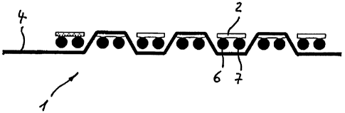
It is evident from the plan view in FIG. 1 that dryer fabric 1 has on the
paper side
wide flat transverse threads (labeled 2 by way of example) that are engaged by
longitudinal thread pairs (labeled 3 by way of example), each longitudinal
thread pair 3
comprising two longitudinal threads (labeled 4, 5 by way of example) that
extend at the
same height within a longitudinal thread pair 3. Longitudinal thread pairs 3
engage with
flat transverse threads 2 in the manner of a plain weave, i.e. they engage one
flat
transverse thread 2 on the paper side and the following flat transverse thread
2 on the
machine side and then once again the subsequent flat transverse thread 2 on
the paper
side.
The engagement of longitudinal threads 4, 5 with flat transverse threads 2 is
even
more clearly evident from FIG. 2. This Figure shows that two round transverse
threads
i5 (labeled 6, 7 by way of example) lie in contact with the underside of each
flat transverse
thread 2 and support it in paired fashion. Any shifting of round trans'verse
threads 6, 7
relative to flat transverse threads 2 is prevented by the alternating
engagement of flat
transverse threads 2 and the associated round transverse threads 6, 7 by
longitudinal
thread pairs 3.
In the version below the dot-dash line, longitudinal threads 4, 5 of
longitudinal
thread pairs 3 form, at end 8 of dryer fabric 1, large loops (labeled 9 by way
of example)
and small loops (labeled 10 by way of example). Large loops 9 alternate with
small loops
10. The version above the dot-dash line illustrates only large loops 9. It is
understood that
this depiction is intended to show two different types of end 8, but that only
one version
5
CA 02308926 2000-05-19
of the loops is present in one dryer fabric. Large loops 9 form loop eyes 11;
these loops 9
can be made to overlap with corresponding large loops at the other end of
dryer fabric in
such a way that all the loop eyes 11 align and thus form a passage through
which, in
known fashion, an inserted wire can be slid in order to join ends 8 and form a
so-called
s inserted wire seam.
The special aspect of the loop configuration is principally the fact that
after the
loop has been formed, one longitudinal thread 4 of a longitudinal thread pair
3 is woven
back in such a way that it forms the adjacent longitudinal thread 12 of the
adjacent
longitudinal thread pair 13. The same is true of longitudinal thread 5 of
longitudinal
io thread pair 3, i.e. as a result of formation of the loop, it becomes the
adjacent longitudinal
thread 14 of the adjacent longitudinal thread pair 15. The result is that
there is little
twisting of loops 9, 10, and dryer fabric 1 has a highly uniform weave pattern
on the
paper side.
Dryer fabric 21 depicted in FIG. 3 differs from dryer fabric 1 according to
FIGS. 1
is and 2 only in terms of the configuration of the transverse threads (labeled
22 by way of
example). These transverse threads 22 are configured as one-piece shaped
cords. Each
transverse thread 22 has on the paper side one flat transverse thread 23, onto
whose
machine side two longitudinal ribs 24, 25 are shaped next to one another.
Longitudinal
ribs 24, 25 have a substantially circular cross section, and increase the
flexural strength of
20 the respective flat transverse thread 23.
Transverse threads 22 are engaged by longitudinal threads 26 in the same way
as
the combination, in dryer fabric 1 shown in FIGS. 1 and 2, of flat transverse
threads 2 and
round transverse threads 6, 7 lying in contact with them on the machine side.
6