Note: Descriptions are shown in the official language in which they were submitted.
CA 02309089 2000-04-27
WO 99/23476 PCT/GB98/01809
1
MEASURING THE CONCENTRATION OF A SiJBSTANCE
The present invention relates to an apparatus and a
method for determining the concentration of a substance.
In one particular application, the invention relates to
apparatus and a method for determining the concentration
of oxygen within living tissue cells.
For clarity, the term "assay substance" will be used
in this specification. to refer to the particular
substance that an apparatus or method according to the
invention is intended to detect.
It is well-known that a large number of fluorescent
dyes measurably change their fluorescing characteristics
in dependance upon the concentration of specific
substances. For example, it is known that the
fluorescence of the fluorophor tris(4,7-diphenyl-1,10-
phenanthroline) ruthenium chloride is decreased in an
inverse relationship to concentration of oxygen. It is
recognised that both the intensity and the duration of
light emitted by fluorescence of this substance are
reduced in the presence of oxygen.
This phenomenon has been applied in measurement of
oxygen tension in tumours, for example, as disclosed in
the paper of W.K.Young, B.Vojnovic and P.Wardman:
"Measurement of oxygen tension in tumours by time-
resolved fluorescence" British Journal of Cancer (1996)
74 (Supl.XXVII) S256-S259. In this disclosure, apparatus
for measuring oxygen tension comprises a sensor in which
a fluorophor is localised in a polymer and coated on an
end surface of an optical fibre. A pulsed laser is used
CA 02309089 2000-04-27
WO 99/23476 PCT/GB98/01809
2
to apply pumping light to the fibre, which light is
transmitted to the fluorophor. Following the pulse, the
fluorophor emits light, which travels back along the
fibre to a detector. An assessment of the concentration
of oxygen present is made on the basis of the time taken
for the fluorescent emission to decay, the rate of decay
increasing with the concentration. This sensor is
advantageous in that it is relatively unreactive with
biological tissue and will not affect living cells even
after a prolonged contact with them, and in that it does
not consume oxygen during detection.
The operation of such apparatus is, to a large
extent, satisfactory. However, the apparatus does have
a major disadvantage. In order to generate fluorescence
of sufficient intensity to be measurable, a high-
intensity light source is needed. In practice, it has
been found that a laser source is required. While laser
sources are readily available, they are relatively
costly, such that they represent a significant portion of
the total cost of a sensor.
It is an aim of the invention to provide a system
for detecting the concentration of an assay substance
which has all of the advantages of the above-described
prior art system, but which does not require use of a
laser light source.
According to a first of its aspects, the invention
provides a sensor for detecting concentration of an assay
substance comprising an optical fibre having an end
surface on which is disposed a polymer body within which
a multiplicity of particles is immobilised, on which
CA 02309089 2000-04-27
WO 99/23476 PCT/GB98/01809
3 -
particles is adsorbed a fluorophor, the polymer being
such as to allow the assay substance to permeate into the
body to come into contact with the fluorophor, and the
fluorophor being selected as having a fluorescent
activity which is measurably altered in the presence of
the assay substance.
It has been found that the pattern of distribution
of the fluorophor in a sensor embodying the invention is
particularly effective in transmitting a high proportion
of the light generated by the fluorophor back along the
fibre for detection.
Preferably, the sensor comprises a single optical
fibre which carries light from a pumping light source to
the polymer body and which carries light emitted by the
fluorophor from the polymer body to a detector. This
further simplifies the construction of the sensor.
It has been found to be advantageous for the numeric
aperture of the optical fibre to be greater than 0.3,
and, in some embodiments, yet more advantageous to be
greater than 0.4. In particularly preferred embodiments,
a numerical aperture on the range 0.45 to 0.5 is
selected. Numerical apertures in these ranges are
particularly suited to collection of light from the
fluorophor in the body of active material.
An optical fibre for use in a sensor embodying the
invention is advantageously of less than 300,um in
diameter. A diameter of approximately 200 ,um has been
found to be particularly suitable.
CA 02309089 2000-04-27
WO 99/23476 PCT/GB98/01809
4 '
The particles may suitably be silica gel particles.
It is generally preferable for such particles to be of as
small a size as possible, since this maximises the
surface area on which dye can be adsorbed and also
promotes cross-linking of the polymer matrix. At present,
silica particles having an average diameter of 5pm are
readily available. It is preferable that the silica
particles are of an average diameter of 5 m or less.
In a particularly useful embodiment of the
invention, the assay substance is oxygen. In such
embodiments, a suitable polymer is a silicone rubber. A
suitable fluorophor for use in such embodiments is a
ruthenium complex dye, for example tris(4,7-diphenyl-
1,10-phenanthroline). However, many other dyes could also
be used, a prime desirable property being that the dye
has a relatively long fluorescent lifetime; preferably in
the order of several s when unquenched by the assay
substance.
In principle, a dye with a short fluorescent
lifetime could be used. If this is the case, a
correspondingly fast light source must be used to excite
the fluorophor, and the light source must be controlled
by suitably fast switching circuitry.
From another of its aspects, the invention provides
a method of making a sensor for measuring the
concentration of an assay substance in which a
fluorescent dye is adsorbed onto a multiplicity of solid
particles, subsequently dispersing the particles in a
liquid polymer, applying the liquid polymer and the
particles contained in it to an end surface of an optical
CA 02309089 2000-04-27
WO 99/23476 PCT/GB98/01809
-
fibre, and curing the liquid polymer to form a polymer
body on the end surface of the optical fibre, the dye
having been selected as to have a fluorescent activity
which is measurably altered in the presence of the assay
5 substance, and the polymer having been selected to be
permeable to the assay surface when in its cured
condition.
In such methods, the optical fibre typically
comprises a core, a cladding, and a protective buffer
coating which covers the cladding. In such cases, the
method includes removal of the buffer coating from an end
portion of the fibre prior to application of the liquid
polymer, and subsequent to curing of the liquid polymer,
a protective coating is applied to cover the said end
portion and the polymer body. In such embodiments, the
protective coating may be formed from the same liquid
polymer as is applied to the end portion of the fibre.
The polymer of the protective coating may be
substantially pure or it may incorporate opaque particles
such as carbon black. This latter arrangement isolates
the fluorophor from ambient light, while the former
arrangement may offer greater acceptability for use in
contact with biological tissue.
Alternatively, the method may include insertion of
the said end portion through a hollow member, such that
its end face, on which the liquid polymer is applied,
projects from the hollow member, and subsequent to curing
of the polymer layer, a protective coating is applied to
cover an end face of the tubular member and the polymer
body. The hollow member may be a hollow needle made, for
example, from steel or a ceramic material. The
CA 02309089 2000-04-27
WO 99/23476 PCT/GB98/01809
6 -
arrangement described in this paragraph has the advantage
of having high mechanical durability.
In a third of its aspects, the invention provides a
system for measuring the concentration of an assay
substance comprising:
a sensor having a sensing body including
fluorophor, which fluorophor has a fluorescent activity
which is measurably altered in relation the concentration
of the assay substance and light conveying means for
conveying light to and from the fluorophor;
a pumping light source which, in operation,
applies light to the light conveying means to activate
the fluorophor;
a detector for detecting light emitted by the
fluorophor in the polymer body and for generating a
signal in response thereto;
analysing apparatus for analysing the signal
generated by the detector, and calculating from that
signal the concentration of assay substance detected by
the sensor; characterised in that
the detector operates to detect transient
change in light emitted by the fluorophor simultaneously
with the pumping light source operating to apply light to
the optical fibre.
This system is particularly advantageous because
operation of the light source simultaneously with the
detector results in a substantially greater amount of
fluorescent light output, than would occur with a pulsed
source of an equivalent brightness operated briefly
before operation of the detector. By virtue of this, the
light source may be a source other than a laser, for
CA 02309089 2000-04-27
WO 99/23476 PCT/GB98/01809
7 -
example, one or more light emitting diodes.
A system according to this aspect of the invention
may operate by analysing the change in the light emitted
by the fluorophor which occurs after the light source
starts to operate. As such, the system analyses the
kinetics of the growth in light output which takes place
in response to operation of the light source. In such a
system, it is normal to operate the light source for a
time which is substantially larger than the time during
which light emitted by the fluorophor changes following
the start of operation of the light source.
In most practical embodiments, the light source is
operated repeatedly, the analysing means being operable
to calculate an average value of a plurality of
calculated concentration values. This arrangement
ensures that random variations in any one measurement do
not substantially affect the accuracy of the system.
It is preferable in a system according to this
aspect of the invention for the sensor to have a single
optical fibre through which light is transmitted to the
fluorophor, and through which light from the fluorophor
is returned to the detector. In such embodiments, the
system typically further comprises an optical means, such
as beam splitter, to split light emerging from the
optical fibre from light which is entering the fibre from
the light source.
In another of its aspects, the invention provides an
analysis system for calculating a lifetime period of an
exponentially varying signal comprising:
CA 02309089 2000-04-27
WO 99/23476 PCT/GB98/01809
8 -
three or more integrating circuits, each having an
input for receiving the signal an output on which is
generated a signal representative of the value of the
input signal integrated over time;
for each integrator, a switch circuit having a
control input and operative to selectively connect or
disconnect the input of the associated integrator to the
signal in dependance upon the state of its control input;
timing means responsive to commencement of
exponential variation of the signal, and operative to
generate control signals for application to the control
inputs of the switch circuits, the control signals being
timed such that the three switches connect their
respective integrating circuits, in turn, to the signal
for three equal and, consecutive time periods during
exponential change of the signal; and
computing means operative to receive output signals
from the integrating circuits, and perform on them
analysis whereby the lifetime value of the exponential
change can be determined.
This system is particularly useful in systems of the
above defined aspects of the invention, but can also find
application in other systems in which high-speed analysis
of exponentially varying signals is needed. Its
particular advantage is that the mathematically difficult
task of performing the integration is carried out in
high-speed, low-cost dedicated hardware. The computing
means can therefore be of relatively low performance,
since it need perform only a few mathematically simple
operations.
The integrating circuits can conveniently be
CA 02309089 2000-04-27
WO 99/23476 PCT/GB98/01809
9 _
implemented as operational amplifier integrators.
It may be that alternative faster integrating
circuits would be required if a dye of relatively short
fluorescent lifetime is used.
The computing means will typically comprise a
digital computer, with a suitable analogue-to-digital
conversion circuit being provided between the integrating
circuits and the computing means. In particularly
convenient embodiments, the computing means comprises a
general-purpose, microprocessor-based computer, such as
a desktop personal computer.
An embodiment of.the invention will now be described
in detail, by way of example, and with reference to the
accompanying drawing in which:
Figure 1 is a cross-sectional view of a sensor for
use in apparatus embodying the invention;
Figure 2 is an alternative sensor to that shown in
Figure 1;
Figure 3 is a schematic diagram of a sensing
apparatus embodying the invention;
Figure 4 is an overview of the signal processing
circuit construction of apparatus embodying the
invention;
Figure 5 is diagram of fluorescent activity in a
sensor plotted against time during operation of a system
embodying the invention;
Figure 6 is a diagram showing the relative timing of
signals within the system (the horizontal time axis being
not to scale); and
Figure 7 is a circuit diagram of an electronic
CA 02309089 2000-04-27
WO 99/23476 PCT/GB98/01809
switching circuit suitable for fast switching of an LED.
With reference to Figs. 1 and 2, there is shown two
alternative sensor arrangements which embody, or form
5 part of various aspects of the invention.
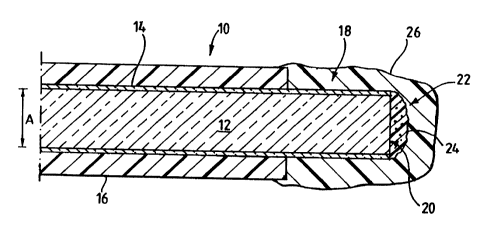
The sensor 10 comprises an optical fibre which is
formed from a light transmitting core 12 surrounded by a
cladding 14. A protective buffer layer 16 surrounds the
10 cladding 14 to give the fibre mechanical strength and
robustness.
The diameter of the fibre, shown at dimension A, is
approximately 200 m. For this exemplary embodiment, the
particular fibre chosen was a TECS (t.m.) optical fibre
manufactured by 3M (t.m.).
The fibre has an end surface 20. An end portion of
the fibre 18, extending from the end surface 20, is bared
of the buffer layer 16. On the end surface 20, there is
formed a body 22. The body comprises a quantity of
moulded polymer formed as a curved projection from the
end surface 20. Within the body 22, a multiplicity of
particles 24 are dispersed.
Each of the particles 24 is formed from silica gel.
The average diameter of the particles is approximately
5 m. A fluorescent dye - tris(4,7-diphenyl-1,10-
phenanthroline)Ru(II)Cl is adsorbed on the surface of the
silica gel particles prior to their being incorporated
into the body. In this way, the dye is immobilised
within the body 22.
CA 02309089 2000-04-27
WO 99/23476 PCT/GB98/01809
11 -
In a first arrangement of the sensor, the end
portion 18 and the body 22 are covered in a moulded
protective coating 26 of the same polymer as forms the
body in a pure form (that is, containing no silica
particles). The protective coating 26 serves to provide
mechanical protection for the body 22 and isolates it
from the clinical environment in which it will be used.
In an alternative arrangement shown in Fig. 2, the end
portion 18 is inserted into a tubular rigid needle 28
which has a central axial through bore. The needle 28 is
arranged such that the end surface 20 of the fibre is
disposed substantially at a free open end of the bore.
A protective coating 30 is applied to cover the body 22
and a surrounding end surface of the needle 28. The
needle 28 is also sealed to the buffer layer 16. By
providing such a rigid needle 28, there is produced a
sensor which has a robust sensing tip. The needle may be
made of steel, other metal, ceramic, or other materials.
This has little bearing on the operation of the sensor.
However, in some embodiments, such as within a magnetic
resonance imaging scanner, the presence of a magnetic or
conductive probe may be undesirable. Alternatively, the
end of the fibre may be enclosed within the bore of the
needle.
For reference now to Fig. 3, a system which
incorporates the sensor of Fig. 1 or Fig. 2 will now be
described.
An overview of the system is shown in Fig. 3. The
system comprises a light source constituted by a light
emitting diode (LED) 40. The light from the LED 40
passes through a 450 nm acetate filter 42 to pass into a
CA 02309089 2000-04-27
WO 99/23476 PCT/GB98/01809
12
first optical fibre 44.
A y-beam splitter is formed by a 2 x 2 splitter 46,
one port of which is unused. A first optical fibre 44 is
connected to a first port on a first side of the splitter
46. A second optical fibre 48 is connected to a port on
the second side of the splitter 46 such that light
entering the splitter 46 through the first optical fibre
44 is transmitted to the second optical fibre 48. The
second optical fibre 48 connects the splitter 46 to a
coupler 50. A third optical fibre 52 is connected to a
second port on the first side of the slitter 46. The
third optical fibre 52 connects the splitter 46 to a
detector unit 54, which will be described in more detail
below.
The LED 40, the splitter 46 and the detector unit 54
are all disposed within a common housing. The coupler 50
permits optical connection of a fibre external of the
housing, through a wall 56, to the second optical fibre
48. In this case, a sensor 10, as described with
reference to Fig. 1 or Fig. 2, is connected to the
coupler 50.
In use, light is emitted from the LED 40, passes
through the acetate filter 42, into the first optical
fibre 44. From there, it passes through the splitter 46
into the second optical fibre 48, and then through the
coupler 50, into the sensor 10. This light causes
fluorescent activity within the body 22 on the end
surface of the sensor 10. Such fluorescent activity
causes light to be produced with an emission spectrum
peaking at around 600 nm. This light travels from the
CA 02309089 2000-04-27
WO 99/23476 PCT/GB98/01809
13 .
sensor 10, through the coupler 50, into the second
optical fibre 48. It then passes through the splitter 46
and into the third optical fibre 52, to be carried to the
detector unit 54.
The detector unit 54 comprises a coupling lens 60,
a 590 nm long-pass filter 62 and a photomultiplier tube
64. Light from the third optical fibre 52 is received by
the coupling lens 60, passes through the filter 62 to be
received by the photomultiplier tube 64. The
photomultiplier tube 64 generates an electrical output
signal which is proportional to the amount of light which
it receives. The apparatus and method for processing
this signal will be described below.
With reference to Fig. 4, the electrical signal from
the photomultiplier tube 64 is received into the signal
processing circuits at a connector 70.
The first stage of processing the signal fed to the
connector is carried out by an amplifier stage 72. The
amplifier stage comprises an operational amplifier
connected as an inverting DC amplifier. The output of
the amplifier stage at 74 is a signal with a voltage
proportional to the amount of light being received by the
photomultiplier tube 64.
The output from the amplifier stage is fed to an
input of an integrating stage 76. The integrating stage
76 comprises three identical integrating channels, each
of which comprises a conventionally designed operational
amplifier integration circuit comprising an operational
amplifier 80 with a capacitor 82 connected between its
CA 02309089 2000-04-27
WO 99/23476 PCT/GB98/01809
14 -
output and its non-inverting input. The inverting input
of the operational amplifier 80 is grounded. The
integrating circuit has a series resistor 84 on its
input.
The integrating stage 76 further comprises three
high-speed electronic channel switches 86. Each switch
86 connects a respective one of the integrating channels
to the input of the integrating stage 76. A respective
electronic resetting switch 88 is also connected across
each of the capacitors 82 to permit discharge of the
capacitor 82 to reset the integrating circuit between
integration operations.
The integrating stage 76 has three outputs 90, each
connected to the output of a respective one of the
integration channels.
The outputs 90 of the integration stage 76 are each
connected to a respective input of a multi-channel
analogue-to-digital (A/D) converter 92. The A/D
converter 92 generates a digital output signal which is
fed to a computer 94 for processing.
The above described circuit is controlled by a
timing stage 96. The timing stage 96 has an output 98 to
control the LED 40, outputs 100,102,104 each of which
controls a respective one of the electronic channel
switches 86, a control output 106 for controlling
operation of the A/D converter 92 and a reset output 108
which simultaneously actuates the three resetting
switches 88. The timing stage also has a start
triggering input line 110.
CA 02309089 2000-04-27
WO 99/23476 PCT/GB98/01809
15 -
A system control circuit 112 is provided to initiate
operation of the timing stage 96 through the triggering
input line. The system control circuit 112 also controls
operation of the computer through an interrupt line 114.
Having described the apparatus of the present
invention, it is now appropriate to describe the
principles behind its operation, and, subsequent to that,
its method of operation.
Immediately after the LED 40 starts to operate, the
fluorophor in the sensor 10 begins to fluoresce. An
oxygen-dependant component of the amount of light being
emitted by such fluorescence grows exponentially to a
steady maximum value within a few ps. In a system such
as this, a lifetime value ti for the exponential growth
varies in dependance upon the degree of fluorescent
activity in the sensor 10. Since the fluorescent
activity is determined by the concentration of oxygen at
the probe tip, if the value of z can be determined, the
concentration of oxygen can then be found.
With reference to the graph Figure 5, the signal
generated by the output of the amplifier stage 72 (and
therefore the amount of light reaching the
photomultiplier tube 64 from fluorescent activity in the
sensor 10) is represented by the line 120. This is
plotted against time on the x-axis. In the graph, the
LED 40 is energised at tzero= The photomultiplier tube
detects a small amount of the light from the LED 40
leaking through the beam splitter 46, shown by the step
change in level at 122.
CA 02309089 2000-04-27
WO 99/23476 PCT/GB98/01809
16 -
Immediately thereafter, the photomultiplier tube 64
begins to detect light emitted by fluorescence in the
sensor. This light increases exponentially, resulting in
an exponential output from the amplifier stage 72, as
represented in Figure 5.
It has been shown that the lifetime t of a transient
exponential growth can be calculated by integration of
the transient curve over three equally-spaced and equal-
length time regions.
In the following, Il represents an integral from
time tO to tl; 12 represents an integral from time tl to
t2; and 13 represents an integral from time t2 to t3.
Each of the intervals`tl-to, t2-tl and t3-t2 is of time
At. In which case:
At
ti=
-1oge ((I2-I3)l(I1-I2))
The initial and the final levels may also be
determined from:
FinalLevel=(I1-I2)1og,(Q)
At(1-Q)2
and
(I1-I2)1(1-e I- T"`)) - (I1-I2)1og,(Q)
Initial(tl)Leve1=(I1- at ) pt(1-
Q)2
where
CA 02309089 2000-04-27
WO 99/23476 PCT/GB98/01809
17 -
_ 12-I3
Q 11-I2
In the present embodiment, the integrations required to
determine the values of 11, 12 and 13 are performed by
the three integrating channels of the integrating stage
76. Furthermore, the integration is performed repeatedly
on a multiplicity of energisations of the LED 40 thereby
to average the integration value, so as to mitigate the
effect of random variations in the integral value which
can arise from noise or other sources.
A measurement sequence will now be described in
detail with reference being made to Figure 6.
In Figure 6, time is represented horizontally. The
horizontal lines each represents the variation in time of
the logic state of a particular signal line within the
system. Each line in Figure 6 is labelled with a
reference numeral which corresponds to the hardware
device or signal line described above which is controlled
by that signal.
The lower part of Figure 6 shows a complete
measurement cycle. The indicated interval A - B is 1
second.
A measurement cycle is initiated by the control
circuit 112 driving the start triggering input line 110
low (active). At the same time, the interrupt line 114
is driven high (inactive). After a delay, the reset line
108 is pulsed to active high, and then brought low again,
the falling edge of the pulse arriving exactly one second
CA 02309089 2000-04-27
WO 99/23476 PCT/GB98/01809
18 -
after the triggering input line 110 was activated.
An acquisition sequence is then started, extending
over interval C. Each acquisition sequence comprises a
multiplicity of integration sequences, each extending
over a variable cycle period shown as D in the upper part
of Figure 6. In the upper part of Figure 6, there is
shown the timing diagram for a minimum-length integration
sequence lasting 50us (upper diagram) and a maximum-
length integration sequence lasting 204.8ps. The number
of integration sequences within an acquisition sequence
is varied in dependance upon the length of each
integration sequence, such that the last integration
sequence commences not longer than 900ms after the start
of the acquisition sequence.
Each integration sequence comprises the following
steps:
1. At a time L (measured from the start of the
integration sequence) the LED control output 98 is driven
high, to turn on the LED 40.
2. Between times tO and ti, the output 100 is
driven high to turn on the first channel switch 86;
between times tl and t2, the output 102 is driven high to
turn on the second channel switch 86, and between times
t1 and t3, the output 104 is driven high to turn on the
third channel switch 86. Each channel is switched on for
the same length of time At(i.e. At = t3-t2 = t2-tl = tl-
t0).
3. After t3, the LED control output 98 is switched
off.
4. A delay is imposed (up to the total cycle
period D) to allow all fluorescent activity to fully
CA 02309089 2000-04-27
WO 99/23476 PCT/GB98/01809
19 -
decay.
As the cycle period D is varied, the time interval
between L and tO remains fixed. As the cycle period D is
varied, the time interval between L and tO remains fixed.
As At is varied, the ratio of LED on-time (L to t3) to
the cycle period D remains constant (in this embodiment,
at a ratio exceeding 1:8). The principle reason for such
variation is to ensure that the three integrations take
place over a time period in which the level of
fluorescent emission is varying rapidly. It has been
found that it is preferable to adjust the cycle period D
such that the relationship:
0.4TSOT5 2.5i
is adhered to.
Following this sequence, it will be seen that each
of the integration circuits will have performed an
integration of the value of the fluorescent activity
which corresponds to a respective one of the values of
integrals Il, 12 or 13 in the formulae given above.
At the end of the acquisition sequence, the
integration will have been performed a multiplicity of
times, thereby mitigating the effect of any random
fluctuation in the signal received from the photodetector
74. Such fluctuations can result from both electronic
noise and from the quantised nature of the photon flux
being detected. A measurement sequence E of
approximately lOOms then starts.
In the measurement sequence E, there is first
imposed a delay to ensure that the final integration
CA 02309089 2000-04-27
WO 99/23476 PCT/GB98/01809
sequence is completed. At the same time, the interrupt
line 114 and the control output 106 are then activated to
trigger operation of the A/D converter 92, which reads
the outputs of the three integrating circuits, and
5 generates a digital value corresponding to each of them.
This digital value is then made available to be read by
the computer 94.
A time period F before the start of the next
10 acquisition sequence, the reset output 108 is activated
to reset the integrating circuits in readiness for the
next acquisition cycle.
It will be seen that the computer 94 can then
15 calculate a value for ti by performing only simple
arithmetical operations plus a single logarithmic
computation. These calculations can readily be performed
by a computer of a comparatively modest power within the
time interval between successive acquisition sequences.
20 This is in notable contrast to the alternative
possibility of using the computer to perform the
integration - a process which would require a very
substantially longer processing time, such that a very
powerful (and expensive) computer would be required to
perform such calculations in real time.
Once the value of T is known, it is readily possible
to calculate the percentage concentration of oxygen at
the probe tip, by means of the Stern-Volmer relation
which specifies that:
ti 1 +tiokLp21
tio
CA 02309089 2000-04-27
WO 99/23476 PCT/GB98/01809
21 -
where to is the lifetime value of the probe in the
absence of oxygen.
It should be noted that this ideal relationship is
not strictly followed at all oxygen tensions. When the
dye is incorporated into a silica/polymer mass, a better
approximation of the oxygen tension can be derived by
using a form of the Stern-Volmer relation modified to
include a Langmuir adsorption isotherm:
=1+S(N[4211(1+N[021))
ti0
where S and N are calibration constants.
Once the computer calculates the value of k, it can
display this for immediate reading by an operator, or the
value can be processed and stored in any desired manner.
For example, the computer may maintain a table of oxygen
concentration values, may provide an instantaneous
display of oxygen concentration, or drive a plotter to
generate a continuous record of the variation in oxygen
concentration over time.
Much of the hardware of the system can be
implemented in a straightforward manner. However, care
must be taken to ensure that the electronic switches
which controls the LED 40 has a fast operating speed to
allow the LED to switch on in a time in the order of
30ns. By this arrangement, an accurate measurement of ti
can be obtained. An example of a suitable driver circuit
is shown in Figure 7. As will be understood, the time
taken to turn the LED off is not critical. This can
CA 02309089 2000-04-27
WO 99/23476 PCT/GB98/01809
22
extend to the order of a few microseconds.
Although the foregoing description has referred to
a sensor for oxygen, the present invention could be
applied, in alternative embodiments, to construct sensors
for other assay substances by selection of a suitable
fluorophor. For example, it is envisaged that hydrogen
ion concentration (pH) could be measured using a
sulphonic acid anilide or other aromatic hydrocarbon
fluorophor, a rhodamine dye, or hydroxypyrenetrisulfonic
acid; oxygen concentration could alternatively be
measured using a fluoranthene dye, pyrenebutyric acid,
polycyclic, homocyclic or heterocyclic aromatic
hydrocarbon or lanthanide and/or osmium complexes; carbon
dioxide concentration could be measured using (3-
methylumbelliferone and sodium bicarbonate, and sulphur
dioxide or hydrogen peroxide could be detected by means
of a fluorophor comprising metal complex in combination
with a long-chain alkyl or alkane group ammonium or
sulphate ion. It is believed that the invention can also
be applied to detection of enzymes using a fluorophor
comprising hydrolase oxidases or dehydrogenases of the
type of enzyme to be detected. It will be appreciated
that the particular formulation of fluorophor required
for a particular measuring task can be selected by
experimentation in a routine manner by a suitably skilled
person.