Note: Descriptions are shown in the official language in which they were submitted.
CA 02309268 2000-OS-08
WO 99/26892 . PCTNS98/24867
METHOD AND APPARATUS FOR INTEGRATING
ORGANIC FIBERS WITH MINERAL FIBERS
TECHNICAL FIELD AND INDUSTRIAL APPLICABILITY OF THE INVENTION
This invention relates to the manufacture of fbrous products for such uses as
thermal and acoustical insulation and as structural molding media. More
particularly, this
invention relates to processes for manufacturing fibrous products having both
mineral
fibers and organic fibers, such as polymer fibers, with the different fibers
being integrated
with each other for beneficial product properties.
BACKGROUND OF THE INVENTION
Mineral fiber products, particularly products made of glass fibers, are
typically
made as either continuous fibers or discontinuous fibers. Various organic
coatings can be
applied to these fibers for protecting the fibers from abrasion, for
connecting the mineral
fibers to each other to form a structural product, and for providing
compatibility of the
mineral fibers with other materials, such as the compatibility between the
reinforcement
fiber and a plastic matrix. In the case of insulation products, the mineral
fibers are usually
bonded together by organic material, such as a phenol/formaldehyde binder, to
form a
spring-like matrix which can recover after compression during packaging. One
mat
product having both glass fibers and fibers of organic material, and
manufactured by a
textile non-woven process, is disclosed in U.S. Patent No. 4,751,134 to
Chenoweth et al.
The application of organic material to the mineral fibers can take several
forms.
Continuous mineral fibers can be run through a bath or across a coater to
apply a coating
to the fibers, such as during the application of a size to continuous fibers.
Alternatively,
the organic material can be sprayed onto the mineral fibers. This method is
commonly
used in the manufacture of insulation products with a rotary process where a
cylindrical
veil of mineral fibers is met with the sprays of the phenol/formaldehyde
binder.
One of the problems with applying aqueous organic binders of the prior art to
cylindrical veils of mineral fibers is that a portion of the binder tends to
evaporate prior to
contact between the liquid binder drop and a mineral fiber in the veil. This
problem is
exacerbated by the need to apply the binder relatively close to the fiberizer,
i.e., where the
hot environment is particularly likely to cause some of the liquid binder
droplets to
CA 02309268 2000-OS-08
WO 99/26892 - PCTIUS98/2a867
evaporate before contacting a glass fiber. The evaporated binder material
becomes a
contaminant in the exhaust air stream of the process and must be cleaned up in
order to
avoid pollution problems. Also, the binder material on the mineral fibers
tends to be
sticky, requiring extensive cleaning of the fiber collection apparatus to
prevent the build-
s up of clumps of glass fiber insulation material which can drop into the
product and cause
a product defect. Further, the binder material must be cured in an oven,
requiring
tremendous energy not only for curing the binder itself, but also for driving
off the water
associated with the binder, and for environmentally cleaning the gaseous by-
products of
the heating and curing process.
Attempts have been made in the past to integrate organic binder materials with
mineral fibers from a rotary process without merely spraying the veil of
fibers with an
aqueous solution of the binder material. For example, U.S. Patent No.
5,123,949 to
Thiessen discloses a rotary fiberizing process where additive particles are
supplied
through the hollow quill or axle of the rotating spinner. The particles are
directed toward
the veil of mineral fibers from a locus within the veil. The additive
particles can be
fibrous in nature, such as cellulose fibers, and also can be resinous material
in a
particulate form.
Another approach in integrating organic material with rotary mineral fibers is
disclosed in U.S. Patent No. 5,614,132 to Bakhshi et aI. A glass rotary
fiberizer is
operated to produce a downwardly moving hollow veil of glass fibers, and a
polymer
fiberizer is operated within the hollow veil to produce polymer fibers within
the veil but
directed radially outwardly toward the glass fibers. The polymer fibers
commingle with
the glass fibers, producing a reinforced resinous product having both glass f
hers and
polymer fibers. While the process of the Bakhshi et al. patent is effective
for making
certain products, it can be desirable in certain instances to move the polymer
fiber
forming environment further from the intensive heat of the mineral fiber
forming
environment.
For example, an alternative to the coaxial rotary commingling process, U.S.
Patent
No. 5,595,584 to Loftus et al, discloses an alternate commingling process
where glass
rotary fiberizers centrifuging glass fibers, and polymer rotary fiberizers
centrifuging
polymer fibers, are positioned alternately with each other arranged along a
collection
2
CA 02309268 2000-OS-08
WO 99126892 _ PCT/US98/24867
surface. The polymer fiberizer can be oriented at an angle to the vertical so
that the flow
of polymer fibers is directed at an angle into contact with the veil of glass
fibers. While
the purpose of the alternate commingling process was to decouple the polymer
fiber
forming environment from the glass fiber forming region, it was perceived to
be quite
difficult to uniformly integrate the rotary-formed polymer fibers into the
veil of glass
fibers. The nonuniformities of the rotary polymer process combined with the
swirling,
chaotic environment of the glass fiber forming region would prohibit
significant
penetration of the polymer fibers into the glass fibers, potentially resulting
in an
unpredictable, laminar product having less than desired properties for some
products
It would be advantageous if there was developed an improved process for
integrating polymer or other organic fibers into a flowing stream of glass
fibers to produce
a generally uniform mix of glass fibers and polymer fibers, preferably uniform
by fiber
distribution and uniform by weight. Such a process should provide protection
for the
polymer material supplied in fibrous form so that the fibers are not subjected
to a hot
environment which could undesirably vaporize the polymer material or otherwise
degrade
the polymer material, or which could soften or melt the polymer fibers into
non-fibrous
particles.
SUMMARY OF THE INVENTION
The above objects as well as other objects not specifically enumerated are
achieved by a method of integrating organic fibers with mineral fibers by
directing a veil
of organic fibers into intersection with a veil of mineral fibers. According
to the present
invention, the method of integrating organic fibers with mineral fibers
includes
centrifuging organic fibers from molten organic material, using a rotating
organic fiber
spinner, directing the organic fibers into a downwardly moving veil of organic
fibers and
gases, with the veil having an inwardly converging shape as it moves downward,
centrifuging mineral fibers from molten mineral material using a rotary
mineral fiber
spinner positioned concentrically within the downwardly moving veil of organic
fibers,
directing the mineral fibers into a downwardly moving veil of mineral fibers
and gases
within the veil of organic fibers, wherein the veil of mineral fibers
intersects with the veil
CA 02309268 2000-OS-08
WO 99126892 . PCTIUS98/248b7
of organic fibers to integrate the mineral fibers with the organic fibers, and
collecting the
integrated mineral fibers and organic fibers as a fibrous pack.
According to this invention, there is also provided apparatus for integrating
organic fibers with mineral fibers including a rotating organic fiber spinner
for
centrifuging organic fibers from molten organic material, an annular polymer
fiber blower
for directing the organic fibers into a downwardly moving veil of organic
fibers and gases,
with the veil having an inwardly converging shape as it moves downward, a
rotary
mineral fiber spinner positioned concentrically within the downwardly moving
veil of
organic fibers for centrifuging mineral fibers from molten mineral material,
an annular
glass fiber blower for directing the mineral fibers into a downwardly moving
veil of
mineral fibers and gases within the veil of organic fibers, wherein the veil
of mineral
fibers intersects with the veil of organic fibers to integrate the mineral
fibers with the
organic fibers, and a collection surface for collecting the integrated mineral
fibers and
organic fibers as a fibrous pack.
BRIEF DESCRIPTION OF THE DRAWINGS
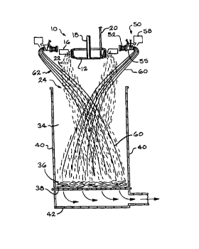
Fig. 1 is a schematic view in elevation of apparatus for integrating polymer
fibers
with glass fibers according to the method of the invention.
Fig. 2 is a partial elevational view of the apparatus of Fig. 1 showing more
detail
of the bearing assembly of the fiberizer of Fig. 1.
Fig. 3 is a schematic plan view of the spinner of the apparatus shown in Fig.
1.
Fig. 4 is schematic view in perspective of the spinner of Fig. 3.
DETAILED DESCRIPTION OF THE INVENTION
This invention will be described using glass fibers as an example of the
mineral
fibers of the invention. It is to be understood that the invention can be
practiced using
mineral fibers of other heat-softenable mineral material, such as rock, slag
and basalt.
Also, although the invention will be described using polymer fibers as the
fibers to be
directed into contact with the glassvfibers, it is to be understood that
fibers of any organic
material, such as asphalt material, can be used with the invention, especially
long or
substantially continuous fibers suitable for enhancing the product properties.
4
CA 02309268 2000-OS-08
WO 99/26892 - _.. PCT/US98I248b7
As shown in Fig. 1, the glass fiberizing apparatus, indicated generally at 10,
includes a spinner 12 and an annular blower 16. The spinner is rotated on an
axle or quill
18. A stream 20 of molten glass is delivered from a glass melting furnace, not
shown, and
the molten stream 20 drops into the interior of the rotating spinner 12. The
centrifugal
forces of the rotating spinner force the molten glass to emanate from the
spinner in the
form of fine glass streams that are turned downwardly as glass fibers 22 by
the action of
the blower 16 and gases induced by the blower. The blower gases and induced
air
attenuate the glass fibers into their final fine diameter, typically within
the range of from
about 3 to about 8 microns. A gas fired burner, not shown, can also be used to
supply
heat to the spinner and the fiber forming environment.
The glass fibers travel in a downwardly moving veil 24, which is generally
cylindrical in shape, and which contains not only the glass fibers, but also
rapidly moving
air from the blower. The veil 24 initially has a diameter slightly larger than
the diameter
of the spinner. The size or diameter of the veil, and the rotational speed of
the gases and
fibers within the veil, change as the veil moves downwardly. These changes are
due to
dissipation of the original energy of the gases within the veil, and on
external forces
influencing the veil.
Nozzles, not shown, can optionally be positioned to direct liquid sprays into
the
veil. Such sprays could include water or other evaporative Liquid to cool the
fibers and
associated gases within the veil. The nozzles could also spray a lubricant
onto the fibers
to reduce fiber-to-fiber friction in the ultimate insulation product, which
could thereby
prevent fiber damage. If desired, the nozzles could also be used to add an
optional
resinous binder to the glass fibers, although the method of the invention
should result in a
product having integrity and recovery properties good enough that a binder is
not needed.
Resinous binders, such as a urea phenol formaldehyde, are well known in the
art. Also,
air lappers, not shown, can be used to discharge air to sweep or direct the
veil 24 from
side to side of the forming hood 34 so that the pack 36 collected on the
moving collection
surface or forming chain 38 will have an even distribution across the width of
the forming
chain, from one hood wall 40 to the other. The forming chain 38 is mounted for
movement as a conveyor, and is foraminous so that a suction box 42, positioned
beneath
the forming chain, can evacuate of gasses from the hood 34 and pack 36.
5
CA 02309268 2000-OS-08
-WO 99/26892 . PCT/US98/24867
Positioned circumferentially outside the glass fiber fiberizing apparatus 10
is a
rotary polymer fiberizing apparatus, indicated generally at 50. The rotary
polymer
fiberizing apparatus 50 can be any suitable rotary equipment suitable for
making fibers
from organic material, including such materials as polymer materials and
asphalt. The
polymer fiberizer 50 is generally comprised of a bearing assembly 52, a
polymer spinner
55, and an annular blower 58. The polymer spinner 55 is mounted for rotation
by means
of the bearing assembly 52. The polymer spinner receives molten polymer
material and
centrifuges it into polymer fibers 60. The annular blower supplies a flow of
air to provide
additional attenuation of the polymer fibers beyond the attenuation supplied
by centrifugal
force. The annular blower also directs the polymer fibers 60 into a downwardly
moving
veil 62 of polymer fibers 60.
As shown more clearly in Fig. 2, the glass spinner has a peripheral wall 66
containing a multiplicity of orifices 68 through which the molten glass is
drawn by
centrifugal force to form the glass fibers 22. The bearing assembly 52 can
include an
inner race 70, a center race 72 and an outer race 74, and a set of ball
bearings 76 between
each of the adjacent races, i.e., between the inner and center races, and
between the center
and outer races. The use of a first set of bearings between the inner and
center races, and
a second set of bearings between the center and outer races gives longer life
to the
bearings 76 since the differences in the relative speed between adjacent races
are reduced.
Thermal insulation material, such as ceramic fiber insulation layers 78, can
be mounted
on the sidewalls of the bearing assembly 52 to protect the bearings and their
lubrication
from the radiant heat radiating from the glass spinner 12. Other designs for
bearing
assemblies for mounting the polymer spinner 55 for rotation can be used.
As shown most clearly in Figs. 2 & 4, the polymer spinner 55 is comprised of
an
outer annular chamber 80 having a peripheral wall 82 containing orifices 84
through
which the molten polymer material flaws to form the polymer fibers 60. A flow
of
molten polymer material is supplied to the outer annular chamber 80 via
polymer feed
tube 86, from a source of molten polymer material, such as an extruder, not
shown. The
polymer fiberizer can be operated under conditions suitable for making polymer
fibers
having a diameter greater than about 5 microns, and preferably within the
range of from
about 4 to about 25 microns, and most preferably about 6 microns. A general
description
6
CA 02309268 2000-OS-08
WO 99126892 _ PCT/US98/24867
of desired process settings, such as temperature, pressure and orifice
diameter, for the
proper operation of a rotary fiberizer for making polymer fibers is found in
U.S. Patent
No. 5,523,031, to Ault et aL, which is hereby incorporated herein by reference
in its
entirety.
The polymer material can be any polymeric material from which fibers of
suitable
length, strength, durability and insulation characteristics can be formed. The
polymer
fiberizer 50 can be operated under conditions suitable for producing short or
long fibers,
but it is preferred to produce substantially continuous lengths. Suitable
polymer materials
for making the polymer fibers include, but are not limited to, polyethylene
terephthalate
(PET), polypropylene, and polyphenylene sulfide (PPS). Other polymer materials
suitable for making fibers include nylon, polycarbonate, polystyrene and
polyamide.
Even though the invention is described using polymer fibers as an example, it
is to be
understood that other materials, including resins, asphalts, and other
thermoplastic and
thermoset materials, can be used as the fibers for use with the present
invention.
Polypropylene and PET are preferred materials for forming the polymer fibers.
As shown in Figs. 2-4, an optional feature of the invention is providing the
polymer spinner 55 with an inner annular chamber 90, which can be used for
either or
both of two separate functions or advantages. First, the inner chamber 90 can
be used as a
hot air plenum to feed incoming hot air along a path across the top of the
polymer spinner
55 and downwardly along the outside of the polymer spinner peripheral wall 82.
A hot air
supply conduit 92 furnishes heating air or other gasses to the inner annular
chamber 90,
and the hot gases are directed by a shield 94 to flow downwardly along the
peripheral wall
82 of the outer annular chamber 80. The hot air is supplied by an air heater,
not shown,
and is preferably at a temperature greater than about 200°C. The shield
can be of any
shape and material suitable for directing the hot gases so that the polymer
spinner wall
and the nascent fibers are maintained in a heated condition. Preferably, the
hot gases are
supplied to the spinner SS at a temperature of at least 200°C, and more
preferably at least
250°C. The shield is not shown in Fig. 3, for clarity. The shield is
advantageously
provided with openings to allow the polymer feed tube 86 and the hot sir
supply conduits
92 to pass through the shield.
7
CA 02309268 2000-OS-08
- WO 99126892 _ PCTIUS98/24867
The second function of the inner annular chamber 90 is to provide a mounting
location for air fins 96 which can be used to drive or rotate the polymer
spinner 55. The
fins 96 drive the polymer spinner SS in a manner similar to the driving action
of a turbine,
i.e., the polymer feed tube 86, the hot air supply conduits 92, and the shield
94 remain
stationary, while the hot air from the conduits 92 contacts the fins 96 to
cause the spinner
55 to rotate. The number of fins 96 and hot air supply conduits 92 can vary,
and the angle
of orientation of the hot air supply conduits with respect to the fins can
also be varied for
optimum results by the propelling gases.
Preferably, approximately 200 standard cubic feet (5.66 cubic meters} of air
per
minute at a temperature of 316°C will be injected into the polymer
spinner at an injection
velocity of about 500 feet per second (152.4 meters per second). A higher or
lower
injection velocity or volume of hot air may be necessary. The volume, velocity
and
temperature of the hot air can be adjusted to optimize the rotation rate as
well as the fiber
forming environment. The polymer spinner can be varied. For a 30 inch (76.2
cm)
diameter spinner, a preferred rotation rate is 1000 revolutions per minute.
Although the hot gases for heating the spinner are described above as being
the
same as the propelling gases for rotating the spinner, it is to be understood
that the hot
gases and the propelling gases could be distinct gases, supplied separately.
Also, it is to
be understood that the polymer spinner could be rotated by different means
other the
air/fin system disclosed above. Further, the polymer fiber spinner 55 can be
rotated at an
angular speed and direction different from the angular speed and direction of
the glass
fiber spinner 12.
The polymer fibers 60 in the polymer fiber veil 62 are directed by the polymer
blower 58 into contact with the glass fibers 22 to integrate the polymer
fibers with the
glass fibers. The intermingled polymer fibers 60 ~ glass fibers 22 are
collected together
in the form of the insulation pack 36. It is to be understood that the method
of the
invention can be carried out using a direct formed fiber collection system,
not shown,
such as disclosed in published PCT application No. WO 95/30787, which is
hereby
incorporated herein by reference in its entirety. The throughput of the
polymer fiberizer
50 will preferably be set to provide a polymer content, by weight, within the
range of
from about 1 to about 10 percent of the expected total throughput of the glass
fibers and
CA 02309268 2000-OS-08
- WO 99126892 _ PC"TNS98I248b7
polymer fibers. For example, if the glass fiber throughput is 1000 pounds per
hour (454
kg/hr) and the desired loss on ignition (LOI) of polymer fibers is 2.5
percent, then the
polymer fiberizer would be configured to have a throughput of about 25.6
pounds per
hour (11.7 kg/hr). The LOI is the percentage of the total material that is
organic and will
burn off when heated.
As shown in Fig. 2, the polymer fiber spinner 55 has a diameter D that is
considerably larger than the diameter d of the glass fiber spinner 12.
Preferably, the
polymer spinner has a diameter D that is within the range of from about 1.3 to
about 2.2
times the diameter of the glass fiber spinner 12. Further, the bearing
assembly 52 has a
diameter dd that is at least 90 percent of the diameter D of the polymer
spinner 55. The
diameter dd of the bearing assembly is measured from the radial center of the
bearing
assembly, as shown in Fig. 2. These diameters are important to limit the
amount of heat
transmitted to the polymer forming environment from the glass forming
environment,
while still allowing effective intermingling. The blower 58 aims its jet of
attenuating
gases at an inwardly converging angle so that the polymer fibers intersect the
veil at a
locus above the forming chain so that the polymer fibers 60 will successfully
intermingle
with the glass fibers 22 before the glass fibers are collected. Otherwise
there will not be
integration of the polymer fibers with the glass fibers, and all or
substantially all of the
polymer material will end up outside or on the top side of the collected
fibrous product. A
balance must be maintained to assure that the polymer fibers are aimed high
enough into
the glass fiber veil 24 for good penetration, and yet not so high that the
polymer fibers
encounter heat sufficient to melt too many of the fibers. It is important to
retain a
majority of the organic material in fibrous form.
The direct pack 36 can be taken through a product shaping oven, not shown,
where
_hot gases are blown through the pack to slightly soften the polymer fibers 60
so that they
bond to the glass fibers to form an insulation product having good pack
integrity.
Preferably, the pack is under vertical compression during the product shaping
process so
that the product thickness is defined. Care must be taken not to heat the
polymer fibers to
such an extent that a substantial portion of the polymer fibers melt or
otherwise lose their
fibrous form. It is important to retain a majority of the organic material in
fibrous form.
Thereafter, the fibrous product can be cooled while still held in vertical
compression.
9
CA 02309268 2000-OS-08
WO 99126892 . PCT/US98/24867
It can be seen by the above discussion that the introduction of relatively
long and
strong polymer fibers into the relatively short glass fibers can be used to
effect different
product attributes in insulation products produced according to the method of
the
invention. The capability and flexibility of the method of the invention will
enable the
manufacture of improved products, having better weight distribution and better
fiber
distribution without the need for auxiliary distribution or lapping devices
for the polymer
fibers. Further, there is an improved control of the nature of the polymer
fiberglass fiber
interface, including the degree of entanglement between the polymer fibers and
the glass
fibers. The fibrous pack can be subjected to a heat setting oven to soften the
polymer
fibers to an extent sufficient to bond the polymer fibers to the glass fibers
without causing
the polymer fibers to lose their fibrous nature. Further, surface layers of
polymer fibers
on fibrous products could be subjected to a heating process to convert the
layer of
polymer fibers into a bonded polymeric network for advantageous product
qualities. Such
a surface layer would make the resulting insulation product stronger and more
amenable
to handling without damage. Also, the fibrous pack could be subjected to a
molding
process in which either the whole fibrous pack or the surfaces of the pack
could be
molded under heat and pressure to form various insulation or structural
products.
Additionally, the introduction of relatively long and strong polymer fibers
into the
predominantly glass fiber pack provides several significant advantages. First
it makes the
pack more suitable for a needling process, which will enable the production of
insulation
products without traditional binders. Second, it advantageously provides
greatly
increased mechanical and tensile strength, thereby allowing the insulation
products to
exhibit improved handleability. For example, binderless wall cavity insulation
products,
capable of being picked up and held by holding one end, can be made using the
method of
the invention. Finally, the polymer fibers are lighter than glass, and on a
weight basis
provide an increased surface area vis-a-vis glass fibers, thereby contributing
to improved
thermal and acoustical performance.
The principle and mode of operation of this invention have been described in
its
preferred embodiment. However, it should be noted that this invention may be
practiced
otherwise than as specifically illustrated and described without departing
from the scope
of the invention.