Note: Descriptions are shown in the official language in which they were submitted.
CA 02309618 2000-OS-09
WO 99/25169 PCT/US98/23759
-1-
MULTIPLE HEAD DISPENSING SYSTEM AND METHOD
Related Applications
This application claims priority from Provisional Application Serial No.
60/065,061, filed
November 10, 1997, which is incorporated herein by reference.
Field of the Invention
The present invention relates generally to an apparatus and method for
performing a
plurality of work operations in parallel using a plurality of work devices
within one workstation.
More specifically, the present invention relates to an apparatus and method
for controlling a
dispensing system that dispenses material onto a substrate using a plurality
of dispensing heads
within a dispensing system.
Background of the Invention
There are several types of prior art dispensing systems used for dispensing
metered
amounts of liquid or paste for a variety of applications. One such application
is in the assembly
of printed circuit boards and integrated circuit chips. In this application,
dispensing systems are
used in the process of encapsulating integrated circuits with an encapsulating
material and in the
process of underfilling flip integrated circuit chips with an encapsulent.
Prior art dispensing
systems are also used for dispensing dots or balls of liquid epoxy or solder
onto circuit boards
and integrated circuits. The liquid epoxy and solder is used to connect
components to a circuit
board or to an integrated circuit. The dispensing systems described above
include those
manufactured and distributed by Camelot Systems, Inc., the assignee of the
present invention,
under the name CAM/ALOT~.
The dispensing systems described above are typically used in an electronics
manufacturing facility in an automated assembly line with other equipment used
in a circuit
board or integrated circuit manufacturing process. The other equipment in-line
with the
dispensing systems may include, for example, pick and place machines, which
place components
on circuit boards, or reflow ovens that are used to cure materials dispensed
onto the circuit
boards or integrated circuits.
In a typical dispensing system, a pump and dispenser assembly is mounted to a
moving
assembly for moving the pump and dispenser assembly along three mutually
orthogonal axes (x,
y, z) using servomotors controlled by a computer system or controller. To
dispense a dot of
CA 02309618 2000-OS-09
WO 99/25169 PCT/US98/23759
-2-
liquid on a circuit board at a desired location, the pump and dispenser
assembly is moved along
the horizontal x and y axes until it is located over the desired location. The
pump and dispenser
assembly is then lowered along the vertical z axis until the nozzle of the
pump and dispenser
assembly is at an appropriate dispensing height over the board. The pump and
dispenser
assembly dispenses a dot of liquid, is then raised along the z axis, moved
along the x and y axes
to a new location, and is lowered along the z axis to dispense the next liquid
dot.
During the manufacture of circuit boards, it is sometimes necessary, or
desirable, to
dispense two different liquids or pastes onto a circuit board or to dispense
different volumes of
the same material. Dispensing systems have been designed that can dispense one
of a number of
dispensing materials from one dispensing head. One example of such a
dispensing system is
described in U.S. Patent Application No. 08/519,146, filed August 24, 1995,
which is
incorporated herein by reference. These dispensing systems typically are only
able to dispense
one material at a time, and the throughput of product in these systems may be
less than desired
because of the time required to dispense multiple materials serially using one
dispensing head.
To overcome the throughput problem, two dispensing systems may be placed
adjacent to
each other with the first dispensing system dispensing one material and the
second dispensing
system dispensing a second material. This solution is expensive since two
complete machines
are used, and since additional manufacturing space is required. In typical
operations,
manufacturing floor space is limited, and it is desirable to limit the
"footprint" of each
manufacturing system on the manufacturing floor.
In electronics assembly, it is not uncommon for some manufacturing systems to
utilize
multiple conveyor systems operating in parallel to increase product throughput
of the systems.
Typical prior art dispensing systems do not include multiple conveyor systems
and are not fully
compatible with other in-line systems using multiple conveyors. Therefore, it
would be desirable
to provide a dispensing system having multiple conveyors.
It is also desirable to provide a multitasking control system for a multiple
conveyor
dispensing system that allows subsystems within the dispensing system to
operate in a
simultaneous, asynchronous manner. In addition, it is desirable for the
control system to allow
remote monitoring and control of the dispensing system by a remote controller
or host computer
of the electronics manufacturing facility.
CA 02309618 2000-OS-09
WO 99/25169 PGT/US98/23759
-3-
Summary of the Invention
Embodiments of the present invention overcome drawbacks of the prior art
discussed
above by providing a multiple head dispensing system having independently
controlled
dispensing heads. Each of the dispensing heads may be independently controlled
to provide
S simultaneous, asynchronous operation and to allow dispensing of different
materials onto
substrates.
In embodiments of the present invention, independent control of the dispensing
heads is
accomplished under the control of a controller in conjunction with a plurality
of gantry systems,
each of which positions one of the multiple dispensing heads over a substrate
that is to receive
dispensing material. In some embodiments, each gantry system utilizes two
drive mechanisms,
arranged in parallel, that provide movement of the dispensing head over an x-y
plane.
In some embodiments of the present invention, multiple conveyor systems are
utilized
that allow parallel processing of work products in the dispensing systems.
Embodiments of the present invention are not limited to dispensing systems,
but also
include other systems utilizing multiple conveyors and multiple work devices
coupled to a
plurality of gantry systems to provide independent movement of each of the
work devices. In
addition, control systems, including control software, in accordance with
embodiments of the
present invention may be used to control equipment other than dispensing
machines, and may be
used to control machines having one, or more than one, work devices.
Brief Description of the Drawings
For a better understanding of the present invention, reference is made to the
drawings
which are incorporated herein by reference and in which:
Fig. I is a perspective view of a multiple head dispensing system in
accordance with one
embodiment of the present invention;
Fig. 2 is a top view of the dispensing system of Fig. 1;
Fig. 3 is a perspective view of a conveyor system used in the dispensing
system of Fig. 1;
Fig. 4 is a top view of the conveyor system shown in Fig. 3;
Fig. 5 is a block diagram showing a block diagram of a control system in
accordance with
one embodiment of the present invention for controlling the dispensing machine
of Fig. 1; and
Fig. 6 is a diagram showing the architecture of the software used in the
controller of the
dispensing system of Fig. 1.
CA 02309618 2000-OS-09
WO 99/25169 PCT/US98/23759
-4-
Detailed Description
For purposes of illustration, embodiments of the present invention will now be
described
with reference primarily to a multiple head dispensing system, however, those
skilled in the art
will appreciate that embodiments of the present invention are not limited to
dispensing systems,
but include other systems in which a work device is used to perform some task
on a product.
Examples of such systems include test and measuring systems, component
placement systems,
inspection systems and machining systems, such as milling machines. In
addition, embodiments
of the present invention may include a number of different types of work
devices within one
system. For example, a system may include a dispensing head, a vision
inspection system, and a
component placement head, each of which may be positioned independently using
its own gantry
system.
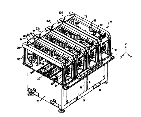
One embodiment of a dispensing system 10 will now be described with reference
to
Figs. l and 2. Fig. 1 shows a perspective view of a multiple head dispensing
system 10 in
accordance with one embodiment of the present invention. For ease of
illustration, the system is
shown in Fig. 1 without an outer covering. Fig. 2 shows a top view of the
dispensing system 10.
The dispensing system 10 includes a lower compartment 12 that is used to house
electrical and pneumatic controllers and a primary system controller. Access
doors 14 and 16 are
mounted on the front of the lower compartment to provide access to the
equipment contained
therein. The top of the lower compartment forms a work surface 18 on which a
dual track
conveyor 20 resides. Mounted to the work surface 18 are four x/y gantry
systems 22a, 22b, 22c
and 22d. Each of the gantry systems supports a dispensing head 24a, 24b, 24c
and 24d which
dispenses material onto substrates loaded into the dispensing system using the
conveyor system
20, and in addition, in some embodiments of the present invention, each of the
gantry systems
supports a camera used as part of a vision system as described below in
further detail. The work
surface 18 has four holes through which four cable troughs 26a, 26b, 26c and
26d pass. Each of
the cable troughs are used to run cables from the control electronics and
pneumatics in the lower
compartment to each of the dispensing heads 24a, 24b, 24c and 24d. In one
embodiment, the
cable troughs are implemented using an E-Chain available from Igus
Corporation.
The gantry systems 22a, 22b, 22c and 22d are substantially identical and in
one
embodiment are implemented using one of the gantry systems disclosed in either
U.S. Patent
Application No. 08/967,682, entitled "Positioning System", or in U.S. Patent
Application No.
08/796,026, also entitled "Positioning System", filed February 6, 1997, both
of which are
CA 02309618 2000-OS-09
WO 99/25169 PCT/US98/23759
-S-
incorporated herein by reference. Gantry system 22a will now be described in
greater detail with
reference to Figs. 1 and 2, it being understood that gantry systems 22b, 22c
and 22d are
substantially identical to gantry system 22a. Gantry system 22a provides
positioning of the
dispensing head 24a along the horizontal, orthogonal x and y axes shown in
Fig. 1. In addition,
gantry system 22a includes a motor for lowering the dispensing head in the
vertical z direction.
Gantry system 22a includes two horizontal support members 26 and 28 and four
vertical
support members 30, 32, 34 and 36 coupled to the work surface 18. A motor
support plate 38 is
coupled between the horizontal support members and is used to support two
motors 74 and 76.
The gantry 22a also includes a plate 50 that is slidably mounted to rails (not
shown) disposed on
the under side of each of the horizontal support members so that the plate can
move along the
y-axis. Dispensing head or pump 24a is mounted to a carriage 60 which in turn
is slidably
mounted to the plate SO to permit movement of the dispensing head along the x-
axis.
Gantry system 22a further includes two nut blocks 66 and 68 that are slidably
movable
along the rails mounted under the horizontal support members 26 and 28. Each
of the nut blocks
is coupled to one of the motors 74, 76 through a respective lead screw 70, 72.
The nut blocks
can be separately driven by the motors using the lead screws to move the nut
blocks along the
y-axis. The carriage 60 is connected to each nut block 66, 68 with respective
rigid trailing arms
80, 82 that are pivotally connected at one end to one of the nut blocks and at
the other end to the
carriage 60. As explained in greater detail in U.S. Patent Application No.
08/796,026, the
dispensing head 24a may be positioned along the x and y axes by moving the nut
blocks along
the y-axis using motors 74 and 76. Motors 74 and 76, as well as the z-axis
motor coupled to the
carriage 60, are controlled by the primary system controller located in the
lower compartment.
The dispensing heads 24a, 24b, 24c and 24d may be implemented using a number
of
different dispensing heads or pumps including those disclosed in U.S. Patent
Application No.
08/562,068, and in U.S. Patent Application 08/885,005, each of which is
incorporated herein by
reference.
The gantry systems 22a, 22b, 22c and 22d provide a significant advantage in
the
dispensing system 10. As described in U.S. Patent Application No. 08/796,026,
the ratio of the
working area beneath the gantry system to the total width of the gantry system
is much greater
for the gantry systems described above than for typical x/y gantry systems.
This reduces the time
required to move a work product between work positions in the multiple head
dispensing system,
and also reduces the total footprint of the dispensing system 10.
CA 02309618 2000-OS-09
WO 99125169 PCT/US98/23759
-6-
The conveyor system 20 will now be described in greater detail with reference
to Figs. 3
and 4. Fig. 3 provides a perspective view of the conveyor system, while Fig. 4
provides a top
view. Several elements of the conveyor system have been removed from the top
view shown in
Fig. 4 for clarity. The conveyor system 70 includes four rails 90, 92, 94 and
96 that define two
lanes, identified as a back lane and a front lane, for transporting work
products, such as circuit
boards, integrated circuit Garners and other substrates into, through, and out
of the dispensing
system 10. The conveyor sections define eight work areas 200, 202, 204, 206,
208, 210, 212,
and 214, as shown in Fig. 4.
Each of the rails comprises four substantially identical, modular conveyor
sections 98,
and each rail of the conveyor system has an end adapter 100 at each end of the
rail. Support
blocks 102 are used to hold rail sections 96 together and to hold the conveyor
sections in place
on the work surface of the dispensing system. The rails are connected by
tracks 104a, 104b,
104c, 104d and 104e, which are mounted to the work surface.
The width wl and w2 of each of the lanes of the conveyor system 20 may be
adjusted by
moving the rails to different positions along the tracks to accommodate
different size work
products. Width wl may be different than width w2.
In one embodiment of the present invention, each of the modular conveyor
sections 98 is
implemented using a conveyor section in accordance with one of the embodiments
disclosed in
U.S. Patent Application No. 08/745,787, filed November 8, 1996, incorporated
herein be
reference. Specifically, the conveyor sections include a driver such as a
pneumatic cylinder with
a caroming plate incorporated into the side of the conveyor section. The
driver is used to lift
work products above the conveyor to a work position beneath one of the
dispensing heads of the
dispensing system.
Each of the conveyor sections includes a conveyor 106 that may be implemented
as a
continuous belt consisting of black neoprene over a cotton cord or may be
implemented as a
series of links. The conveyor 106 is wrapped around four pulleys 108a, 108b,
108c and 108d. A
total of eight drive shafts, four drive shafts 110 and four drive shafts 111,
are used to operate the
conveyors. Each of the drive shafts is coupled to its own motor 112 to allow
independent
operation of each pair of conveyor sections. Operation of each of the motors
is controlled by the
primary system controller. For simplification, only two of the motors 112 are
shown in Fig. 3.
Four drive shafts 110 are used to drive the conveyor segments in the back
lane, and four
drive shafts 111 are used to drive the conveyor segments in the front lane.
For uniformity and
ease of manufacturing, all eight drive shafts are substantially identical, and
each of the
CA 02309618 2000-OS-09
WO 99/25169 PCT/US98/23759
_7_
driveshafts extends through all four rails. Cogs are selectively added to the
lower pulleys 108a
and 108d to cause the pulleys to rotate with the drive shafts. In the conveyor
system 20, for all
conveyor sections in the back lane, the lower pulleys closest to the input
side of the conveyor
system include a cog, and the lower pulleys closest to the output side of the
conveyor system do
not have a cog. For all conveyor sections in the front lane, the lower pulleys
closest to the input
side of the conveyor system do not include a cog, and the lower pulleys
closest to the output side
of the conveyor system do include a cog. This implementation allows each pair
of conveyor
sections, defining one of the work areas, to operate independently. As
understood by those
skilled in the art, to meet specific application demands, the cogs may be
arranged in other
configurations.
Each of the end adapters 100 has a conveyor 101 that is coupled to the
conveyor 106 of
the adjacent conveyor section using an extension piece 103 so that each
conveyor 101 is driven
by the conveyor 106 of the adjacent conveyor section.
As described above, all of the conveyor sections 98 are substantially
identical. In
addition, each conveyor section is symmetrical about a vertical axis
perpendicular to the
direction of conveyor travel and passing through the middle of the conveyor
section. This allows
identical conveyor sections to be used on opposite rails of the same lane, and
at any position (i.e.,
at the input end, output end, or in the middle) in any of the rails.
The conveyor system 20 includes several features that make it particularly
desirable for
use in the multiple head dispensing system 10. First, because the conveyor
system is constructed
using independently controllable, modular sections, the length of the conveyor
system can be
readily adjusted. Specifically, the number of segments used in each rail of
each lane of the
conveyor system may be adapted to correspond to the number of dispensing heads
or other
workpieces used in the dispensing system.
Second, the width of each rail segment in one embodiment of the present
invention is
only 0.56 inches thick. This is accomplished by incorporating a thin lifting
plate within the side
of each conveyor segment, as discussed above. Further, in some embodiments of
the present
invention, the conveyor belt is not used in clamping the work product in place
at the proper work
position. Rather, a clamp consisting of an independent blade which is easily
removable and can
be customized for a given application is used. In addition, an easily
removable insert can be
added to each segment to reduce the effective width of the conveyor to
accommodate a variety of
work products. The use of thin rail segments is desirable in embodiments of
the present
invention to reduce non-productive slew time as a dispensing head is moved
from a completed
CA 02309618 2000-OS-09
WO 99/25169 PCT/US98/23959
_8_
work product in the first lane of the dispensing system to another work
product in the second
lane of the dispensing system.
The control system of the dispensing system will now be described with
reference to
Fig. 5, which shows a block diagram of the control system 300. The primary
component of the
control system is the system controller 302 which is implemented in one
embodiment of the
present invention using a personal computer with an Intel Pentium~ II
processor running a
version of the Microsoft Windows~ NT Operating System, preferably, version 4.0
or later. The
controller is coupled to the conveyor system 20 and each pump 24a, 24b, 24c,
and 24d through a
communications bus 318, which in one embodiment is physically contained within
the motion
controller 304 (described below). The controller 302 is also coupled to each
of the gantry
systems 22a, 22b, 22c and 22d.
The controller 302 includes a system board 310, a vision processor 306, two
motion
controllers 304 and 308, an ethernet card 312, a modem 314, and an internal
bus 302 connecting
the components of the controller. The controller may also include a user
interface apparatus such
as a keyboard, mouse, trackball and monitor coupled to the internal bus 308.
The motion control boards 304 and 308, under the control of the system board,
provide
signals for controlling: motion of the gantry systems; the dispensing of
materials from the
pumps; and the movement of the conveyor system 20. In one embodiment of the
present
invention, each of the motion controller boards are implemented using a Delta
Tau PMAC2
Ultralite motion card available from Delta Tau Data Systems, Inc., Northridge,
CA, and each of
the cards controls two of the gantry systems.
The vision processor 306 controls and processes signals received from cameras
320
mounted on the gantry systems, and provides processed vision signals to the
system board 310.
In embodiments of the present invention, the cameras may be used: to locate
fiducial marks on
work products loaded into the dispensing system for alignment purposes; to
inspect work
products after material has been dispensed, or some other operation has been
performed, and to
identify a type of work product loaded into the dispensing system. In one
embodiment of the
present invention, the vision processor is implemented using a Matrox Meteor
Board available
from Matrox Electronics Systems Ltd. of Montreal, Canada, and the cameras are
implemented
using RS-170 compliant cameras available from Sony.
The ethernet card 312 and the modem 314 are not required in all embodiments of
the
present invention, however, they provide the capability of remote
communications for the
controller 302.
CA 02309618 2000-OS-09
WO 99/25169 PC1'/US98/23759
-9-
The overall architecture of the software loaded on the system board 310 and
the
subsystems that operate within the software will now be described with
reference to Fig. 6. The
overall software architecture for the control system uses a three-tier
client/server model with the
three tiers being chassis clients, chassis server, and vision server. The
software is designed to be
event-driven rather than polled. Accordingly, active objects or subsystems in
the control
software will suspend themselves until a message is received, and it is the
responsibility of the
messaging subsystem (described below) to provide basic services for sending,
receiving and
waiting on messages between subsystems.
In Fig. 6, block 310 represents the software contained within the system
board, and each
of the dark boxes 326, 328, 330, 332, 334 and 336 within block 310 represents
a Windows NT
process operating on the system board, with block 326 representing the chassis
server process
and blocks 328, 330, 332, 334 and 336 representing chassis client processes.
Blocks 348, 340
and 342 represent chassis client processes operating external to the system
board, block 328
represents the vision server process, and block 320 represents physical
chassis clients which may
include one or more local or remote devices from which the operation of the
dispensing system
can be monitored and controlled. Contained within each of the dark boxes,
representing a
process, are labeled white boxes which represent subsystems of the processes.
Each of the processes, and the subsystems contained within the processes will
now be
further described beginning with those subsystems contained within the chassis
server process
326. The chassis server process encompasses software that controls the
physical equipment (i.e.,
the gantry systems, the dispensing heads, and the conveyor systems), except
for the vision
equipment, associated with the dispensing system. The chassis server process
is implemented
using a single process to facilitate maximum bandwidth for communications
between subsystems
contained within the chassis server process. In one embodiment of the present
invention, the
software code used to implement the chassis server process is written in C++.
The message subsystem 340, contained within the chassis server, provides a
standardized
message system for performing all inter-subsystem communication. The message
subsystem is
capable of delivering messages to recipients (identified as consumers) in the
same process as the
consumer and to consumers in different processes using RPC (Remote Procedure
Call) calls to
deliver messages across boundaries.
The connection services subsystem 342 is responsible for managing local and
remote
client connections to the chassis server. The connection services subsystem
provides a globally
accessible connection port for use by chassis clients, manages the creation
and deletion of special
CA 02309618 2000-OS-09
WO 99/25169 PCT/US98/23759
- 10-
connections used for transferring large amounts of data, and provides
arbitration services for
determining which of the chassis clients is designated as a master client. The
concept of master
client is discussed further below.
The chassis supervisor 348 is responsible for the overall control and
coordination of the
dispensing system and for guaranteeing the safety of the equipment. It
provides control and
synchronization over the following subordinate subsystems: head supervisor
364; pattern
services 362; conveyor 350; light tower 346; and the vision processor 306.
The pattern services subsystem 362 provides pattern services for the
dispensing system.
The pattern services subsystem acts essentially as a database containing
patterns or recipes that
define dispense head positions to create predefined patterns of dispensed
materials on substrates.
The pattern services subsystem provides pattern read/write services, pattern
upload/download
services, management of subpatterns of a recipe, and operators for retrieving
a next instruction
for a specific dispensing head based on a recipe selected for the dispensing
head. In
embodiments of the present invention, the recipes may include some or all of
the following:
substrate characteristics (i.e., board dimensions), the sequence of operations
to be performed on
the substrate, a representation of features of a substrate to be identified by
the vision system, and
any other information related to the overall process. Additional patterns or
recipes may be added
to the pattern services subsystem using DLLs (Dynamic Link Libraries).
The conveyor subsystem 350 is responsible for managing the overall state of
the
conveyor system of the dispensing system. Specifically, the conveyor system
performs the
following functions: selectively turning conveyor segments and/or lanes on and
off as
appropriate; managing handshaking with machines upstream and downstream from
the
dispensing system in an assembly line using SMEMA (Surface Mount Equipment
Manufacturers
Association) protocols; and notifying the chassis supervisor of events such as
the location of
circuit boards in the dispensing system via the message subsystem. The
conveyor subsystem
uses a state machine for managing each conveyor segment and for coordinating
the movement of
each conveyor segment with its neighbors to bring new substrates in and move
existing
substrates out at the earliest point in time.
The head supervisor subsystem 364 has the responsibility for controlling
position of the
dispensing heads to perform a desired dispensing operation based on commands
received from
the chassis supervisor having pattern or recipe data provided by the pattern
services subsystem.
A separate instance of a head supervisor object is created for each dispensing
head controlled by
the control system. Each instance of the head supervisor object includes a
message receiver, a
CA 02309618 2000-OS-09
WO 99/25169 PCT/US98/Z3759
-11-
state machine, an execution thread to sequence a dispensing head through a
pattern or recipe, an
X,Y,Z, pump control object (described further below) for communicating with
the motion
controller cards to provide head motion and pump control, and a Z sense object
(which is
described further below).
The X,Y,Z, pump control object 366 is responsible for performing dispense
operations.
These operations do not require real-time response from the chassis services
process, but rather,
are carned out by the motion controllers in response to a packet of
information describing the
operation provided by the X,Y,Z, pump control object.
The Z sense object 368 is responsible for determining the height of each of
the dispensing
heads above the substrates and operates in conjunction with a mechanical touch
probe or some
other device such as a laser sensor. The height information generated by the Z
sense object is
used to accurately position a dispensing needle of the dispensing heads at a
proper dispensing
height over the substrate.
The I/O services subsystem 352 provides a logical interface for all I/O points
supported
by the dispensing machine. This subsystem is designed to be both configurable
and extensible
by using information stored in the database services subsystem 370 to define
controller
information including: identification of controllers contained in the control
system; device
specific initialization data for the controllers; and available I/O points on
the controllers. The I/O
services subsystem also defines I/O point configuration information including:
logical name of
specific I/O points; board assignments and bit assignments.
The motion control manager subsystem 352 provides a generic logical interface
for
motion control to allow additional options to be added to the dispensing
system which require
motion control capabilities.
The alarm manager subsystem 344 and the light tower subsystem 346 provide
control for
an audible alarm and for a light tower attached to the dispensing system.
The log manager subsystem 358 can be configured to receive messages from any
other
subsystem. The log manager creates a log of received messages on disk for
subsequent retrieval.
The log manager also supports query services of stored information using date,
subsystem, and
other fields for selective retrieval of data.
The debug subsystem 354 is responsible for providing a standard set of
mechanisms
which all other subsystems can utilize for reporting and/or logging of debug
information.
The database services subsystem 370 is responsible for providing a generic set
of services
for storage and retrieval of all chassis related persistent data, including
system initialization data,
CA 02309618 2000-OS-09
WO 99/25169 PCT/US98/Z3759
-12-
except for the actual dispense patterns or recipes which are managed by the
pattern services
subsystem. In embodiments of the present invention, the information managed by
this
subsystem includes: user security records; controller information; I/O logical-
to-physical
mapping information; motion control axis logical-to-physical information;
general system
configuration information such as pump configurations, conveyor configuration,
and log file
configuration; substrate tracking data; and current pattern information.
In embodiments of the present invention, there are a number of different
chassis clients
that can be simultaneously connected to the chassis server. Additionally,
there may be multiple
instances of a particular type of client simultaneously connected to the
chassis server. There is a
separate NT process for each of the chassis clients. In the embodiment shown
in Fig. 6, there are
four different types ofNT processes shown, monitor 336, SPC (remote 338 and
local
334),GEM/SEC (remote 340 and local 332, and GUI (remote 342 and local 332) for
connecting
to different types of chassis clients. In other embodiments, there may be more
or less chassis
clients, and other types of chassis clients, such as an application developed
by a user of the
dispensing system.
The GLTI process allows remote and local users to monitor and/or control the
dispensing
machine using standard graphical user interface devices. In one embodiment of
the present
invention, the controller of the dispensing machine includes a monitor,
keyboard and a trackball
or mouse to provide a physical user interface that communicates with the
dispensing machine
through the local GLJI process 330. In other embodiments, a remote computer
may provide the
physical user interface and connect to the controller of the dispensing system
through a RAS
(Remote Access Service) connection.
The GEM/SECS (General Equipment Model/Semiconductor Communication Standards)
process provides an interface for a factory cell or host computer. In
manufacturing facilities it is
often desirable to have a central control and monitoring facility. The
GEM/SECS process
enables embodiments of the dispensing machine to be monitored and controlled
by a host
computer.
The SPC process is used in embodiments of the present invention to support
statistical
process control, and may be implemented either within the dispensing system
controller or in a
remote processor. The SPC process is contained in a process separate from the
chassis server to
isolate it from the chassis server process to enable it to be operated as a
remote process when
desired.
CA 02309618 2000-OS-09
WO 99/25169 PCT/US98/23759
-13-
The monitor process provides the ability for a remote or local process to
monitor the
overall activity of the chassis server process. In embodiments of the present
invention, the
monitor process may be used to track all connections, processes, threads and
critical objects, and
may be used to assist in performing diagnostics, including remote diagnostics.
As described above, a number of clients may access the chassis server to
monitor
operation of the dispensing system. However, in a preferred embodiment of the
present
invention, only one client, referred to as a master, can control the
dispensing system at a time. In
this embodiment, upon initialization of a system using initialization data
contained in the
database system, the GUI software operating on the controller in the
dispensing equipment is
designated as the master client. The GUI software on the controller may pass
the master
designation to remote clients, and after passing the master to a remote
client, may subsequently
retrieve it again.
The vision process 328 is an NT process distinct from the client processes and
the chassis
server process. The vision process provides the software for communicating
with the vision
processor 306 and the vision hardware in the dispensing machine. The primary
client of the
vision process is the chassis server process, and more specifically, instances
of the head
supervisor that make requests to the vision process to, for example, locate an
object (such as a
fiducial mark) prior to or during execution of a recipe.
In embodiments of the present invention, there are several advantages to
implementing
the vision process as a distinct process from the chassis server process.
First, there is a tight
coupling between the GUI and the vision system, to provide a user with images
generated by the
vision system. Therefore, it is desirable that the vision process and the GUI
process be run in the
same computer, and in embodiments of the present invention utilizing a remote
GUI (i.e., a
remote computer), since the vision process is a distinct process, it may be
run in the same
computer as the GUI.
Second, there is a loose connection between the vision system and the chassis
server
since minimal amounts of data are transferred between these processes during
normal operation
of the dispensing system.
Third, performance gains may be realized in embodiments of the present
invention due to
multiprocessing provided by the vision process in parallel with the processing
occurring in the
head supervisors. This may be particularly true for embodiments of the present
invention
incorporating several gantry systems operating simultaneously, so that several
instances of head
supervisors are also operating simultaneously.
CA 02309618 2000-OS-09
WO 99/25169 PCT/US98/23759
-14-
An additional advantage to implementing the vision process as a distinct
process is that
data libraries, available from different vendors, may be included without
introducing possible
errors into the core chassis server process. In one embodiment of the present
invention, the
vision process is implemented using software from Matrox.
The implementation of the control system described above provides several
advantages.
First, the three tier design approach provides separation of machine control,
real-time functions
from less performance-critical software, such as the client processes, and
allows execution of
client processes on remote computers. Second, it provides a standard interface
that can be
utilized by different types of clients. Third, the software is designed to
perform many activities
in parallel, asynchronously. For example, implementing the head supervisor of
each dispensing
head using separate instances, allows the dispensing heads to operate in
parallel in an
asynchronous manner providing greater flexibility in the operation of the
dispensing system.
The operation of the dispensing system 10 will now be described. While
specific modes
of operation are described herein, one of the significant advantages of
embodiments of the
present invention is the flexibility of the dispensing system to operate in a
variety of modes, and
embodiments of the present invention are not limited to the specific modes
described herein. In
one mode of operation, the dispensing system is configured for dispensing
material on one type
of circuit board in four separate operations, one operation being performed by
each of the four
dispensing heads. The front lane and the back lane are both configured to
receive the same type
of circuit board. In this configuration, when circuit boards are being indexed
in one lane,
dispensing can occur on the circuit boards in the other lane. This
configuration increases the
overall throughput of circuit boards compared to typical prior art dispensing
systems, and
reduces the amount of idle time of the dispensing heads due to indexing of
circuit boards. This
mode of operation employs a pipelined, parallel architecture to increase total
system throughput.
In another mode of operation of the dispensing system 10, the system may be
used to
increase throughput even though a circuit board (or some other substrate) is
to receive only one
type of dispensing material, and the dispensing task requires only one size
dispensing needle.
For this mode of operation, each of the dispensing heads are substantially
identical, and the
overall dispensing task is divided and organized among the dispensing heads to
provide the most
efficient mode of operation. The division of the dispensing task among the
dispensing heads
may be accomplished in one of number of ways. The division may be made based
on types of
dots to be dispensed, based on dispensing locations on the circuit boards, or
on other criteria.
CA 02309618 2000-OS-09
WO 99/25169 PCT/US98/23759
-15-
In the embodiments discussed above, the number of conveyor sections in each
rail is
equal to the number of dispensing heads in the dispensing system. In other
embodiments, the
number of conveyor sections may be greater than the number of dispensing
heads, and a gap may
be provided between two of the gantry systems to provide a conveyor buffer
segment. Such a
buffer segment may be used as a preheat segment or for any other application
that may require or
benefit from a buffer segment.
In one embodiment of the present invention, the number of conveyor sections
may be
some multiple of the number of gantry systems. This provides additional
flexibility in the
operation of the system, and is useful when a work product, such as a circuit
board, is larger than
the work area of one of the gantry systems.
Embodiments of the present invention utilizing a dual lane conveyor system
overcome
drawbacks of prior art single lane dispensing systems by providing a system
that is compatible
with other dual lane manufacturing equipment in an automated assembly line. In
addition, the
multiple lane embodiments described herein may also be implemented into
assembly lines with
single lane equipment using a board shuttling mechanism between the multiple
lane dispenser
and other equipment. This is useful for relatively slow dispensing operations.
Further,
embodiments of the present invention provide for the dispensing of multiple
materials within one
dispensing system while maintaining high throughput rates.
Embodiments of the dispensing system described above include four gantry
systems and
a two lane conveyor system. As readily understood by one skilled in the art,
dispensing systems
(and other multiple workpiece machines) in accordance with embodiments of the
present
invention may include more or less than four gantry systems and a conveyor
system having more
or less than two lanes.
In one embodiment of the present invention, the vision system described- above
is used to
determine a type of circuit board or some other substrate that has been
received by the dispensing
system. In this embodiment, the control system, based on output signals from
the vision system
indicative of the type of circuit board, selects a pattern or recipe defining
an operation to be
performed on the board, and controls the dispensing system to perform the
operation. In other
embodiments, systems other than the vision system may be used to determine the
type of circuit
board received. For example, optical decoders, or other devices such as bar
code readers, rnay be
used.
Embodiments of the present invention directed to the control system and
control software
used to monitor and control the dispensing system are not limited for use with
dispensing
CA 02309618 2000-OS-09
WO 99/25169 PGTNS98/23759
-16-
systems or multiple gantry machines. Rather, embodiments of the control system
may be used
with other machines and devices.
Having thus described at least one illustrative embodiment of the invention,
various
alterations, modifications and improvements will readily occur to those
skilled in the art. Such
alterations, modifications and improvements are intended to be within the
scope and spirit of the
invention. Accordingly, the foregoing description is by way of example only
and is not intended
as limiting.
What is claimed is: