Note: Descriptions are shown in the official language in which they were submitted.
CA 02309647 2000-05-09
- 1 -
Pressure frame, designed in particular for an aircraft
The invention relates to a pressure frame, designed in
particular for an aircraft and consisting of a dome-shaped cover
made of composite materials reinforced with fibers, preferably
in one single piece, and cover reinforcing devices connected to
said cover or produced integrally therewith.
For economic reasons, the flight altitude of passenger aircraft
is chosen as high as possible, because in higher altitudes there
is less air resistance, resulting in less fuel consumption.
Common flight altitudes are in the range of 10 000 to 12 000 m
(32 808 to 39 370 ft.). Such altitudes, however, are not
appropriate for humans, because atmospheric pressure is low, the
air does not contain much oxygen, and the air temperature is
low. Therefore, the conditions inside the fuselage of an
aircraft must be adapted to the living conditions humans are
used to. This is done by creating a cabin atmosphere
corresponding to an altitude of about 3000 m (9842 ft.). Because
the difference in pressure between the inside of the aircraft
and its environment corresponds to a difference in altitude of
about 7000 to 9000 m (22 966 to 29 527 ft.), the interior of the
aircraft must be designed as a pressure chamber which is able to
withstand such pressure differences. For this purpose there are
so-called pressure frames at the front and rear ends of the
fuselage, which are designed to withstand these strains.
The rear pressure frame is usually in the form of a dome-shaped
cover, with the concave side facing the aircraft cabin. Known
pressure frames consist of a plurality of reinforcing profiles
distributed in radial direction and in the direction of
concentric circles and are connected to each other e.g. by means
of rivets. The skeleton thus formed is covered with overlapping
metal parts which are attached to each other and to said
reinforcing elements. Therefore, the production of such pressure
frames is considerably complicated and costly. If said metal
cover starts cracking, there is the risk that the crack will
develop further so that the pressure frame will break and
CA 02309647 2000-05-09
.
- 2 -
pressure will escape from the passenger cabin to the rear, which
may lead to a crash of the aircraft. Therefore, in order to make
the aircraft as safe as possible, it must be made sure that, if
a crack develops, it is prevented from developing further so
that pressure can not drop suddenly or like in an explosion.
This aim is reached by keeping the sheet metal areas without
reinforcing profiles as small as possible; in addition, e.g.
crack stoppers made of titanium sheets have to be installed,
which makes production even more complicated. In aircraft for
several hundred passengers, the rear pressure frame is about 3.5
to 4 m (11.5 to 13,1 ft.) in diameter. Such dimensions result in
a relatively high weight of about 100 kg (220 pounds), which has
a particularly negative effect because it is far away from the
center of gravity of the aircraft.
From EP 387 400 B1 a pressure frame made of composite materials
reinforced with fibers for the pressure fuselage of an aircraft
is known, which is as light-weight as possible, cheap to produce
and easy to install. In order to reach these aims, said pressure
frame has a non-uniform fiber layer structure which is more
rigid at the periphery than in the center. The periphery of the
dome-shaped cover is formed such that it will adapt to the
cross-section of the fuselage and is easy to install, e.g. by
gluing or riveting. This eliminates the need for an additional
frame to install the pressure frame in the aircraft fuselage.
The data of the embodiment described show that said pressure
frame is intended for relatively small aircraft. In larger
aircraft for several hundred passengers some enormous
aerodynamic forces act on the sides of the pressure frame, e.g.
from the rudder unit forces or thrusts of the power units. In
large aircraft the pressure frame is about 3.5 to 4 m (11.5 to
13,1 ft.) in diameter. Such dimensions result in an increased
risk of the cover being turned inside out towards the aircraft
cabin, i.e. in the direction of the concave side of the cover,
if the pressure difference between the cabin and the environment
is suddenly reversed. Such reversion of pressure difference may
e.g. happen if the aircraft is sinking quickly.
CA 02309647 2000-05-09
- 3 -
Therefore, the aim of the invention is to provide a pressure
frame designed in particular for aircraft, which is as light-
weight as possible, may be produced as quickly and cheaply as
possible and still meets the strain requirements, particularly
for large aircraft. In addition, the risk of destroying the
pressure frame by the cover being turned inside out towards the
inside of the aircraft is to be reduced. The disadvantages of
known pressure frames are to be avoided or at least reduced.
The aim of the present invention is reached by providing a cover
of essentially uniform thickness and mounting at least one cover
reinforcing device in the central area of the concave side of
the cover. Particularly in large aircraft it is necessary and
useful to disconnect the cover of the pressure frame from the
structure frame, which e.g. has to absorb rudder unit forces or
power unit thrusts, by means of a "resiliently bending"
peripheral connection so that any side forces can not negatively
affect the cover. Therefore, it is useful to attach the cover to
the fuselage via a stable profile, which is why said cover need
not be more rigid or thicker at the periphery. This, in turn,
results in less material being necessary, which means that the
structure will have less weight. The term "essentially the same
thickness" is meant to include optionally thicker edges around
openings or holes in the cover which serve to reinforce these
weak points of the cover. The cover reinforcing device provided
in the central area of the cover, which device is mounted on the
cover on its concave side and is connected to the cover or
produced integrally therewith, results in considerably improved
stability, because if the pressure difference is reversed,
bulging areas will be considerably smaller, thus keeping the
cover from being completely turned inside out towards the inside
and thus from being destroyed. Appropriate construction of said
cover reinforcing device in the central area of the cover allows
further reduction in thickness of the cover material without the
pressure frame falling short of security requirements.
According to another feature of the invention, said cover
reinforcing device located in the central area is formed by a
CA 02309647 2000-05-09
- 4 -
reinforcing structure oriented against the curvature of the
cover, for example a truncated cone-shaped, mug-shaped or
parabolic structure, with a cavity being arranged between the
cover and the reinforcing structure. This provides optimum
rigidity, particularly in the central area of the cover, thus
reducing the probability of the cover being turned inside out.
Checking the cover of a pressure frame is one of the regular
tasks of aircraft inspection. Therefore, according to another
feature of the invention, inspection openings for the inspection
of the cover part behind the reinforcing structure are arranged
in the reinforcing structure in the central area of the cover.
These openings will also save material and thus weight. Care
must be taken, however, so as that said openings do not
substantially reduce the stability of the structure.
Moreover, reinforcing profiles are mounted on the concave side
of the cover, particularly in radial direction, which profiles
are connected to the cover or produced integrally therewith.
Apart from any connecting elements between the cover and the
reinforcing devices or the fuselage, the pressure frame is
solely made of plastic material reinforced with fibers. Fiber
materials are glass, carbon or aramide (aromatic polyamides). As
plastic material, preferably duroplast or thermoplast are used.
Fabric is highly tear-resistant and tear-tolerant compared to
metal and therefore allows a thinner and thus lighter structure.
Further features of the invention will be explained in greater
detail with reference to the attached drawings, wherein
Fig. 1 shows a schematic longitudinal section of an aircraft
fuselage,
Fig. 2 shows an embodiment of the pressure frame as seen from
inside the aircraft looking in the direction opposite the
flight direction,
Fig. 3 shows a section of the pressure frame according to fig. 2
along the line III-III,
CA 02309647 2000-05-09
- 5 -
Fig. 4 shows a section along the line IV-IV in fig. 2 in greater
detail,
Fig. 5 shows detail A of fig. 3, enlarged,
Fig. 6 shows detail B of fig. 3, enlarged,
Fig. 7 shows another embodiment of a pressure frame as seen from
inside the aircraft looking in the direction opposite the
flight direction.
Fig. 1 is a schematic representation of a fuselage 1 in the
longitudinal direction of the aircraft. The inner compartment 2
of the aircraft, which is designed as a pressure chamber, is
hatched. The pressure frame 3 is located at the rear end of the
inner compartment 2 of the aircraft. Said frame has the form of
a dome-shaped cover, with the concave side being oriented
towards the inside 2 of the aircraft and usually being provided
with reinforcements (not shown) which keep the cover from
turning inside out towards the inside 2 of the aircraft. The
pressure frame 3 is securely and tightly connected to the
fuselage 1. The shape of the cover is adapted to the cross-
section of the fuselage 2 and may therefore be of round,
elliptical or another shape. Depending on the application, the
curvature of the cover of the pressure frame 3 may be of
circular, parabolic, hyperbolic or another shape.
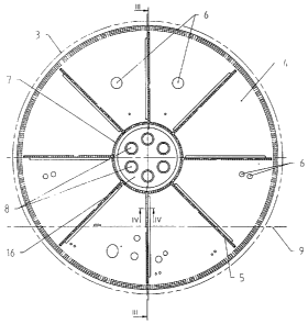
Fig. 2 shows an embodiment of a pressure frame 3 according to
the present invention as seen from inside the aircraft looking
in the direction opposite the flight direction. The pressure
frame 3 consists of a cover 4 made of one single piece. However,
if necessary for production reasons, said cover 4 may e.g. also
be made of several pieces. In order to reinforce said cover 4, a
reinforcing structure 7 is provided on the concave side of said
cover 4 concentrically around the center, and it is connected to
said cover 4 or produced integrally therewith. In the example
shown, said reinforcing structure has the shape of a truncated
cone, but other constructions oriented against the curvature of
said cover 4 may be provided as well, such as e.g. a parabolic
or mug-shaped structure. The bottom 16 of said truncated cone-
shaped reinforcing structure 7 has inspection openings 8
CA 02309647 2000-05-09
- 6 -
provided for the inspection of the part of cover 4 lying behind
them. This is necessary because said cover has to be checked
regularly. Moreover, said inspection openings 8 help reduce
weight without substantially reducing the stability of the
structure. Particularly in large aircraft, wherein the cover is
up to 3.5 to 4 m (11.5 to 13,1 ft.) in diameter, reinforcing
profiles 5 are provided radially on the concave side of cover 4
for further reinforcement, which profiles are connected to said
cover 4 or are produced integrally therewith. The reinforcing
structure 7 and the reinforcing profiles 5 are also made of
plastic material reinforced with fibers, like said cover 4. Said
cover 4 has various openings 6 to make room for electric wires,
hydraulic or fuel lines and pressure compensation valves. For
reinforcement, said cover 4 may be thicker in the region of such
openings 6, so that the development of cracks from an opening 6
can largely be avoided. Apart from that, said cover 4 is of
essentially uniform thickness, which is an advantage in
production. The size and shape of the central reinforcing
structure 7 is chosen as desired depending on application
requirements, but said openings 6 in said cover 4 must be taken
into account. Instead of a round shape, said reinforcing
structure 7 may also be of polygonal shape. In the drawing, the
floor level 9 of the aircraft cabin is indicated by a dashed
line.
Fig. 3 shows the section along the line III-III in fig. 2. The
radial lines on the cover 4 indicate the connections 10 of the
reinforcing profiles 5 with said cover 4. The reinforcing
structure 7 and the reinforcing profiles 5 prevent said cover 4
from turning inside out towards the inside of the aircraft. This
figure shows better that the central reinforcing structure 7 has
the shape of a truncated cone. Other constructions may be
provided as well, such as e.g. a structure like a dome-shaped
cover whose curvature is oriented against the curvature of said
cover 4 and which structure is connected to said cover 4. Said
reinforcing profiles 5 are preferably arranged radially on said
cover 4, but it is also possible to arrange said reinforcing
CA 02309647 2000-05-09
- 7 -
profiles 5 at an angle with respect to the radial direction and,
in addition, tangentially.
In Fig. 4, which shows the section along the line IV-IV in fig.
2 in greater detail, a reinforcing profile 5 and its connection
to the cover 4 are represented. In this embodiment, the radially
arranged reinforcing profile 5 has a Z-shaped cross-section,
with one leg of said reinforcing profile 5 being connected to
said cover 4 via a threaded rivet 11. Said threaded rivet 11 may
e.g. be made of titanium. This screw joint is advantageously
sealed, for which purpose the rivet is "set wet", i.e. it is
provided with sealing material and then screwed in. For further
sealing, a seal 12 is provided between said reinforcing profile
and said cover 4 at the point of connection. Said seal 12 may
be made of polysulfide based sealing material usually used for
the construction of aircraft, which has the form of a paste and
exhibits permanently resilient behavior. However, said cover 4
and said reinforcing profile 5 may also be connected in other
ways, e.g. by gluing.
Fig. 5, which shows detail A of fig. 3, represents the
connection of the reinforcing structure 7 to the cover 4. For
this purpose, the edge of the truncated cone-shaped reinforcing
structure 7 is connected to the cover 4 by means of a threaded
rivet 11. In addition, part of a radial reinforcing profile 5
overlaps the region at the edge of said reinforcing structure 7
and is also connected to said cover 4 by means of said threaded
rivet 11. Further threaded rivets 11 serve to connect the
radially arranged reinforcing profile 5 with said cover 4. Any
gaps are provided with a seal 12, which usually is in the form
of a sealing material.
Detail B of fig. 3 is enlarged in fig. 6, wherein the connection
between the pressure frame 3 and the fuselage is indicated. They
are connected via a connecting knee 13, which is securely and
tightly connected to the outer edge of the cover 4 via
connecting elements 14. Said connecting knee 13 may e.g. be made
of titanium and is a relatively resilient connection when
CA 02309647 2000-05-09
- 8 -
bended. The structure frame 17, which is connected to the
aircraft planking 18 and said connecting knee 13, absorbs side
forces, e.g. originating from the rudder units or power unit
thrusts, and thus prevents these forces from straining said
pressure frame 3. This disconnection of the cover 4 of said
pressure frame 3 from said structure frame 17 of the fuselage is
particularly important in large aircraft. Said cover 4 only has
to seal the inside of the aircraft and need not absorb the
external forces from the sides as well, which are absorbed by
said structure frame 17 itself. An insulating layer, e.g. a
layer of glass or epoxy, may be provided between said pressure
frame 3 and said connection to the fuselage. This prevents
electrochemical corrosion of the connecting elements by
electrolysis due to the electric conduction. Moreover, said
cover 4 is usually provided with ground points to ground said
pressure frame 3.
Fig. 7 shows an embodiment of a pressure frame according to the
present invention, wherein further reinforcing profiles 15 are
provided along a concentric circle in addition to the
reinforcing structure 7 in the central area of the cover and the
radial reinforcing profiles S. An increase in the number of
reinforcing profiles makes the areas of the cover 4 behind them
smaller and thus increases the stability of the structure. In
addition, the more complex reinforcing structures 5, 7, 15 help
further reduce the thickness of said cover 4, thus saving
material and weight. Instead of the circular reinforcing
profiles 15, straight reinforcing profiles forming a polygon are
also possible, of course.
Advantageously the pressure frame 3 according to the present
invention is prepared such that the cover 4 together with the
reinforcing structure 7 and the reinforcing profiles 5, 15 are
produced in one piece in one step. The so-called resin transfer
molding (RTM) technology has advantages over the conventional
production process using an autoclave wherein the prepreg
material is cured. According to the RTM process, the dry fibers
are introduced into a mold corresponding to the shape of the
CA 02309647 2000-05-09
- 9 -
object to be produced, and then a special resin having
relatively low viscosity is pressed into the closed mold,
optionally under the action of a vacuum. The mold is heated in
order to further reduce the viscosity of the resin and to
provide an undisturbed flow in the mold. Then the resin
impregnating the fibers hardens. According to the RTM process,
more complicated objects may be produced easily, quickly and
relatively cheaply. Therefore, in the present case, said cover 4
of said pressure frame 3 together with all reinforcing
structures 5, 7, and 15 may be produced in one step. This means
that no additional time is required to connect said cover 4 to
said reinforcing devices 5, 7, 15, and the tightness of said
pressure frame 3 is increased.
Of course, it is possible to apply the present pressure frame to
other types of aircraft or comparable objects wherein a
difference in pressure between the inside and the environment
must be maintained for sure.