Note: Descriptions are shown in the official language in which they were submitted.
CA 02309708 2000-05-10
WO 99/25943 1 PCT/EP98/07079
LATCH-AND-BOLT LOCK WITH SIMULTANEOUS CLOSURE ACTUATION OF
BOLT AND LATCH
Technical Field
The present invention relates to a latch-and-bolt
block in which the actuation of the bolt into the closure
position occurs simultaneously with the closure actuation
of the latch.
Background art
In latch-and-bolt locks, actuation of the bolt into
the closure position can occur only after the latch has
already engaged the corresponding selvage, particularly
after closing a door from the outside. When a door provided
with a latch-and-bolt lock is closed from the outside, the
door is first of all set ajar until the latch snaps into
the position for engaging the corresponding selvage and
then the bolt is actuated into the closure position by
means of the key.
However, it can be convenient to have the bolt move
into the closure position automatically, i.e., without
having to use the key, when the door is closed from
outside. The key would be used only to open the door from
outside.
Disclosure of the Invention
The aim of the present invention is to provide a lock
which allows to actuate the bolt into the closure position
simultaneously with the engagement of the latch in the
corresponding selvage.
Within the scope of this aim, an object of the present
invention is to provide a lock in which actuation of the
bolt simultaneously with the latch occurs both when closing
CA 02309708 2006-10-12
2
the door and when opening it.
Another object of the present invention is to provide
a lock which is capable of achieving the above aim and
object with a structure which is constructively simple and
therefore economical and highly reliable in operation.
Accordingly, in one aspect, the invention provides a
latch-and-bolt lock with simultaneous actuation of the bolt
and of the latch during closure, said latch and said bolt
being actuated. by elastic means so as to protrude from the
lock for engagement in respective selvages of doorjamb,
said latch-and-bolt comprising:
a sensor for detecting a closed position of a door when
the lock is fitted on the door, said sensor being movable
at right angles to a faceplate of the lock between an
external position and an internal position relative to said
lock, said sensor being retainable in said internal
position by abutment against a doorjamb of the door when
the lock is fitted on the door;
a slider which is guided parallel to said latch;
a blocking plate for blocking said bolt which is guided
transversely to said slider;
a lever which is articulated to said slider and has a
first arm which is operatively associated with said sensor
and a second arm which is adapted to assume a position for
blocking said latch when said sensor and said latch are
inside the lock; and
an actuation member for the actuation of said blocking
plate being arranged on said slider, said actuation member
being such that when said latch, after abutment against the
doorjamb of the door when the lock is fitted on the door,
is aligned with a corresponding selvage of the doorjamb, by
means of the stroke of said latch for engagement in said
selvage, said slider is moved into a position in which said
CA 02309708 2006-10-12
2a
actuation member disengages said blocking plate from said
bolt and engages said bolt in the corresponding selvage
under the thrust of elastic means.
Brief description of the drawings
Further characteristics and advantages of the present
invention will become apparent from the following detailed
description of a preferred embodiment of the invention,
illustrated by way of nonlimitative example in the
accompanying drawings, wherein:
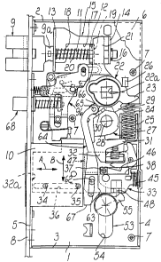
Figure 1 is a plan view of the inside of the lock
according to the present invention;
Figure 2 is an enlarged-scale view of a detail of
Figure 1, with sectional lines in order to better
illustrate some internal components;
Figures 3 and 4 are views of the lock in various
operating conditions.
Ways of carrying out the Invention
In the drawings, the reference numerals which
designate the constructive elements of the lock are shown
on the four figures for the sake of clarity.
With particular reference to Figures 1 and 2, the lock
comprises a case having a flat rectangular prism-like
shape. The case is composed of a bottom wall 1 from which
an upper wall 2, a lower wall 3, a rear wall 4 and a front
wall 5 protrude upwards, forming a compartment for
containing the various parts which is closed by a cover 6
CA 02309708 2000-05-10
WO 99/25943 3 PCT/EP98/07079
which can be fixed by means of screws which engage
respective bushes 7 which protrude into the compartment
from the bottom 1.
The case is inserted in a recess of the door and is
fixed with the aid of a faceplate 8 which is associated
with the front wall 5. The faceplate 8 closes the recess
and is fixed by means of screws which are driven through
its opposite ends and extend above the upper wall 2 and
below the lower wall 3.
The lock comprises a latch 9 and a bolt 10 which are
slideable in the direction A and are adapted to protrude
from the case through openings of the wall 5 and of the
faceplate 8 in order to engage respective selvages of the
jamb in the door closure position.
The latch 9 is provided with a stem 11 which is guided
through a cross-member 12 which is fixed at right angles to
the bottom 1. The stem 11 passes through two wings 13, 14
which are folded at 90 and belong to a bracket 15 which is
slideable in contact with the bottom 1 and is retained on
2D the stem 11 by a ring 16. The bracket has a recess 17 which
forms two edges 18, 19 arranged on opposite sides with
respect to the cross-member 12.
A spring 20 is mounted on the stem 11 and is
interposed between the cross-member 12 and the wing 13 and
actuates said wing so that it rests on a shoulder 9a of the
latch 9 and therefore keeps the latch 9 in a position in
which it protrudes from the case. In this position, which
is determined by the abutment of the edge 19 against the
cross-member 12, a space remains between the wing 14 and
the cross-member 12; a finger 21 enters the space and is
CA 02309708 2000-05-10
WO 99/25943 4 PCTIEP98/07079
radially rigidly coupled to a hub 22 which is rotatably
supported in seats of the bottom 1 and of the cover 6.
A sauare hole 22a is formed in the hub 22 for the
engagement of the square pivot of a handle, not shown,
which by means of the finger 21 allows to actuate the latch
9 for opening.
The hub 22 has a tab 23 which is radial and arranged
at approximately 900 with respect to the finger 21. A
spring 24 acts on the tab 23 and rests on a U-shaped
element 25 which is fixed internally and adjacent to the
rear wall 4 of the case. The spring 24, by acting on the
tab 23, keeps the hub 22 in abutment against a raised
portion 26 protruding from the bottom 1.
In the above-described lock a panic-safe device is
provided which allows, by acting on the handle from the
inside, to simultaneously return the latch 9 and the bolt
10 to the opening position, i.e., to the position in which
they retract into the case. A device of this kind is
described for example in Italian Patents no. 1,233,297 and
1,253,045 in the name of the same Applicant.
Said device comprises a lever 27 which has a pivot 28
in the case and can be rotated by the hub 22 on operation
of the handle. For this purpose, the hub 22 has a tooth 29
which is suitable to act on a respective lug 30 of the
lever 27.
The lever 27 has a triangular tab 31 and an extension
32 which, by means of a mechanism described hereafter,
allow to release and respectively move the bolt into the
case of the lock during opening.
A seat 32a is formed in the bolt 10 on the opposite
CA 02309708 2000-05-10
WO 99/25943 5 PCTIEP98/07079
side with respect to the one that protrudes from the
faceplate 8, and a portion of a plate-like tang 33 is
engaged in the seat 32a.
The bolt 10 is associated with the plate-like tang 33
so that a movement of the tang is matched by an increased
stroke of the bolt. The tang 33 is guided in the sliding
direction A by a pair of pins 34, 35 which engage a slot 36
(see also Figure 4) of the tang, which lies inside the seat
32a, and by a square pin 37, which is fixed to the bottom 1
of the case and slidingly engages a slot 38 of the tang
portion lying outside the bolt.
As shown more clearly in Figure 4, the tang 33 and the
bolt 10 are crossed by two pins 39, 39a; the first pin 39
is rigidly coupled to the tang and slides in a groove 40
formed inside the seat 32a, while the second pin 39a is
rigidly coupled to the bolt and slides within a slot 41 of
the tang.
The pins 39, 39a engage a slot link 42 which is formed
in a linkage 43 which is supported so that it can oscillate
around a pivot 44 which is fixed to the bottom 1 of the
case. A spring 45 is interposed between the tang 33 and the
rear wall 4 and acts so as to assist the outward movement
of the bolt 10 from the case.
The linkage 43 acts as an element for increasing the
stroke of the bolt. The linkage 43 in fact converts the
stroke of the tang 33 into an increased stroke of the bolt
by means of the ratio between the lengths of the arms of
the pins 39, 39a with respect to the pivot 44, so as to
cause an increased protrusion of the bolt from the
faceplate 8 and a deeper penetration thereof into the
CA 02309708 2000-05-10
WO 99/25943 6 PCT/EP98/07079
selvage that has to receive it. The square pin 37, besides
acting as a guiding member for the tang 33, acts as an
element for preventing the sliding of the bolt.
As shown more clearly in Figure 3, the square pin 37
co-operates with a tooth 46 of a plate like pawl 47 which
is substantially C-shaped and is guided in the direction B
at right angles to the direction A by the engagement of two
wings 48, 49 in respective slots 50, 51 of the tang. The
wings 48, 49 rigidly couple the pawl 47 in the direction A
to the tang 33, which accordingly, when it moves, shifts
the pawl along with it.
The pawl 47 is actuated by a spring 52, in which one
end abuts against a tab of the tang and the other end acts
on the wing 49, so as to keep the tooth 46 in a position
for blocking the pin 37 and therefore blocking the tang 33
and the bolt 10.
In order to release the bolt 10, the pawl 47 is
actuated by means of the lever 27, on operation of the
handle, or by means of a known type of key-operated
cylinder 53, which is adapted to be accommodated in a seat
54 of the case and to act by means of its bit 55 on the
wing 48 of the pawl.
The lever 27 acts on the pawl 47 by means of a detent
56 which is pivoted on the tang 33 by means of a pivot 57.
The detent 56 comprises two arms 58, 59 which are
arranged in an L-shaped configuration and between which a
tab 60 is provided which, together with the arm 59, forms a
hollow 61 in which the wing 49 engages. The triangular tab
31 of the lever 27 is meant to act on the arm 58 so as to
make the detent 56 rotate so as to allow the arm 59 to act
CA 02309708 2000-05-10
WO-99/25943 7 PCTIEP98/07079
on the wing 49 and therefore lift the pawl 47 to a level
whereat the tooth 46 allows the square pin 37 to slide in
the slot 38.
The tang 33 is furthermore provided with a transverse
pin 62 which is slideable in a slot 63 formed in a linkage
64 which is articulated at one end to a lug 66 of the hub
22 by means of a pivot 65. The end of the lever 64 that
lies opposite to the pivot 65 has a flat region 67 which,
when the bolt 10 is in the position for retraction into the
case, is within the range of action of the bit 55, so as to
allow the actuation of the latch by acting on the cylinder
53.
From the above description it is evident that in
order to open the lock with the handle, starting from a
condition in which both the latch 9 and the bolt 10 are
engaged in their respective selvages (position shown in
Figure 4), the rotation of the hub 22, whereto the handle
is rotationally coupled, determines by means of the finger
21 the retraction of the latch 9 and at the same time, by
means of the engagement of the tooth 29 on the lug 30, the
rotation of the lever 27, the triangular tab 31 whereof, by
acting on the arm 58, rotates the detent 56 so as to lift
the wing 49 and therefore the pawl 33. The upward movement
of the pawl 33 releases the square pin 37 and engages the
arm 32 against the wing 49, which being pushed toward the
rear wall 4 moves with it the tang 33 and the bolt 10.
According to the fundamental prerogative of the
present invention, the lock allows to automatically engage
the bolt 10 in the respective selvage of the doorjamb
simultaneously with the engagement of the latch. In
CA 02309708 2000-05-10
WO 99/25943 8 PCT/EP98/07079
practice this occurs without actuating the handle or
cylinder 53 but simply by using the retraction and
protrusion motion performed by the latch 9 by first
striking the jamb when the door closes and by then engaging
the respective selvage under the thrust of the spring 20.
For this purpose, the lock comprises a sensor for
detecting the closed position of the door which is
constituted by a secondary latch 68 (see Figures 1 and 2)
which is provided with a flange 69 which is slideable in an
1o opening of the faceplate 8.
A stem 70 protrudes towards the inside of the case
from the secondary latch 68, which like the latch 9 has a
front chamfer so as to be able to retract into the case
when it strikes the jamb. The stem 70 is guided in a cross-
member 71 which is blocked between the bottom 1 and the
cover 6.
A bracket 72 is fixed on the stem 70 and is provided
with two wings 73, 74 which are adjacent to the flange 69
and to the end of the stem. A bridge 75 lies between the
wings 73, 74 and is parallel to the stem 70; a chamfer 76
is formed on one edge of said bridge and forms a raised
portion 77. A spring 78a is arranged on the stem 70 and
acts between the cross-member 71 and the wing 73 and
accordingly pushes the secondary latch 68 outward.
A slider 78 is arranged above the bracket 70 and is
constituted by a plate provided with a pair of slots 79, 80
which are elongated in a direction which is parallel to the
direction A. Respective pins 81, 82 engage in the slots 79,
80, protrude from the bottom 1 and guide the slider 78 in
the direction A.
CA 02309708 2000-05-10
WO 99/25943 9 PCTIEP98/07079
An L-shaped lever 84 is articulated in a rocker-like
manner on the slider 78 by means of a pivot 83 and has a
first arm 85 which is directed downward and whereon a
spring 86 acts. When the secondary latch 68 lies outside
the faceplate 8, said spring keeps the end of the arm 85 in
abutment against the raised portion 77 of the bracket 76,
while when the secondary latch is retracted into the case,
the spring 86 keeps the arm 85 in abutment against a stud
86a of the slider 78. The lever 84 has a second arm 87
which extends from the pivot 83 toward the rear wall 4;
when the arm 85 abuts against the stud 86a, said arm 87
protrudes from the upper edge of the slider 78 in a
position for interfering with the wing 13 of the bracket
15.
A detent 89 is further pivoted, by means of a pivot
88, on the slider 78 and is provided with a raised portion
90 which forms a ramp 91. A spring 92 is wound on the pivot
88 and the opposite ends of said spring abut below the
raised portion 90 and below a tab 93 of the slider 78 so as
to actuate the detent 89 against a stud 94 for stopping the
slider so that the ramp 91 is inclined with respect to the
sliding direction A.
The ramp 91 is meant to be engaged by a pin 95 which
protrudes from the lower face of a plate 96 (see Figure 1)
which lies above the lever 84, the stem 70 and the detent
89.
The plate 96 has two slots 97, 98 which are parallel
to the direction B and in which the guiding pin 81 of the
slider 78 and an additional pin 99, rigidly coupled to the
bottom of the case, engage.
CA 02309708 2000-05-10
WO 99/25943 10 PCT/EP98/07079
The lower end of the plate 96 has a step 100 which is
suitable to interfere with an edge 101 of the tang 33 and a
lobe 102 whereon one end of a spring 103 acts. The spring 103 is coiled on a
post 104 which is rigidly coupled to the
bottom 1 and whose opposite end abuts against the pin 99.
The spring 103 actuates the plate 96 toward the bolt 10 in
a position for blocking the tang 33 in which the step 100
abuts against the edge 101 of the tang 33.
The actuation of the bolt 10 simultaneously with the
latch during door closure occurs as follows.
When the door is open, the lock is in the condition
shown in Figure 1, in which the latch 9 and the secondary
latch 68 protrude from the faceplate 8 and the bolt 10 lies
inside the lock. Since the spring 78a is stronger than the
spring 86, the secondary latch 68 is retained by the spring
78a in abutment against the plate 8, while the arm 85 of
the lever 84 is retained in abutment against the raised
portion 77 of the bracket 72. The second arm 87 of the
lever 84 is orientated horizontally and does not interfere
with the lower edge of the wing 13. The action of the
spring 86 on the lever 84 keeps the slider 78 in a
retention position which is determined by the abutments of
the pins 81, 82 in the slots 79, 80. The bolt 10 is
retained inside the case by means of the step 100 of the
plate 96, which locks the tang 33 by engaging the edge 101.
When the door is closed, the latch 9 and the secondary
latch 68 make contact with the jamb and are forced to
retract into the case of the lock. The retraction stroke of
the secondary latch 68 allows the lever 84 to rotatA and
allows the arm 87 to accordingly assume a position in which
CA 02309708 2000-05-10
WO 99/25943 11 PCT/EP98/07079
it interferes with the wing 13 (see Figure 3) as soon as
said wing has moved beyond the end of the arm 87.
When the latch 9 has aligned with the corresponding
selvage in the jamb, it is again pushed outward by the
spring 20. The secondary latch 68 instead remains inside
the case because it does not have a corresponding selvage.
By means of the outward movement of the latch 9, the
wing 13 abuts against the end of the arm 87, the slider 78
is moved toward the faceplate 8 and the pivot 95 engages
against the ramp 91 of the detent 89 and therefore the
plate 96 is raised in the direction B toward the upper wall
2 in contrast with the return action applied by the spring
103.
This movement causes the disengagement of the step 100
from the edge 101 of the tang 33 and the protrusion of the
faceplate of the bolt 10, which is pushed by the spring 45.
The lock is at this point in the transient condition
shown in Figure 4, in which the pin 95 has moved beyond the
ramp 91.
At this point, by means of the spring 103, the plate
96 is drawn downward into a position in which it rests on
the back of the tang 33 and is ready to be set again by
means of the engagement of the step 100 against the edge
101 as soon as the bolt has retracted.
In order to open the lock it is possible to act on the
handle, i.e., on the hub 22, or by means of the cylinder
53.
In the first case, as mentioned above, the latch 9 is
caused to retract by the finger 21 and simultaneously the
bolt is retracted by means of the lever 27 which, after
CA 02309708 2006-10-12
12
releasing the pawl 47 by means of the triangular tab 31 and
the detent 56, acts on the tang of the bolt with the
extension 32 by means of the wing 49.
In the second case, first of all the bolt retracts by
means of the actuation produced by the bit 55, which by
means of a first turn, after lifting the pawl 47 in order
to release the square pin 37, moves the tang 33 toward the
rear wall 4 and then, by means of a second turn, acts on
the linkage 64, which returns the latch 9 to the retraction
position by means of the hub 22 and the lever 21.
It is evident that the present invention perfectly
achieves the intended aim and objects. In particular, it
should be observed that protrusion of the bolt occurs only
when the latch has already engaged the respective selvage
of the jamb. This ensures perfect alignment of the bolt
with its selvage and safe engagement therein.
The present invention is susceptible of numerous
modifications and variations, all of which are within the
scope of the same inventive concept. In particular, it
should be observed that the simultaneous actuation of the
latch and of the bolt can be generalized to all locks
provided with a latch and a bolt.