Note: Descriptions are shown in the official language in which they were submitted.
CA 02309740 2000-OS-10
WO 99/24309 PGT/US98I21918
CONTROL OF AN ACTIVE SUSPENSION SYSTEM FOR A NORIt VEHICLE
BASED UPON A PARAMETER OF ANOTHER VEHICLE SYSTEM
FIELD OF THE INVENTION
The present invention relates generally to the field
of active suspension systems. More particularly, the
invention relates to an active suspension system for a
work vehicle which includes at least one active vibration
isolator, wherein a control circuit communicates between
the isolator and another vehicle system and generates
control signals for the isolator which depend at least
partly upon a parameter of the another vehicle system.
BACKGROUND OF THE INVENTION
The ride quality and operator comfort of a work
vehicle is adversely affected by vibrations or movement
transmitted from the frame or chassis of the vehicle to
the operator's cab. As the work vehicle travels across a
surface, movement of the chassis induces the operator's
cab to pitch, roll and bounce. Movement of the cab can
be particularly severe in agricultural and construction
equipment vehicles (e. g., tractors, combines, backhoes,
cranes, dozers, trenchers, skid-steer loaders, etc.)
because such vehicles typically operate on off-road
surfaces or fields having a high level of bumpiness.
Operator comfort may also be adversely affected by
the operation of various systems on a work vehicle. In
particular, operation of various work vehicle systems can
cause forces to be applied to the chassis of the vehicle
CA 02309740 2000-OS-10
WO 99/Z4309 PCT/I1S98/Z1918
- 2 -
which, in turn, are transmitted to the cab. Examples of
these forces include the following: draft forces exerted
on the hitch of an agricultural tractor by an implement
(e. g., a plow) which can cause the cab to pitch; normal
forces applied to a work vehicle as the vehicle turns in
response to a steering device which can cause the cab to
roll; clutch forces generated when a work vehicle clutch
(e.g., a main drive clutch; four-wheel drive clutch) is
engaged or disengaged which can cause the cab to pitch;
gear shift forces generated when a transmission of a work
vehicle is shifted which can cause the cab to pitch;
braking forces generated as brakes of a work vehicle are
operated which can cause the cab to pitch; acceleration
forces generated when a speed actuator changes the speed
of a work vehicle which can cause the cab to pitch; etc.
The movement of the cab caused by surface bumps and
the operation of vehicle systems cause both qualitative
and quantitative problems. An operator of such a vehicle
experiences increased levels of discomfort and fatigue
caused by the vibrations. Productivity is decreased when
an operator is forced to rest or shorten the work day, or
is unable to efficiently control the work vehicle. The
operator is also less likely to be satisfied with a work
vehicle which provides poor ride quality. Under certain
conditions, the frequency and magnitude of cab movement
may force the operator to decrease driving speed, further
decreasing productivity.
To improve ride quality and operator comfort, work
vehicles have been equipped with passive, semi-active or
active suspension systems to isolate the operator fram
vibrations caused by surface bumps. Such systems include
vibration isolators mounted between the chassis and cab
or seat. Passive systems use passive vibration isolators
(e. g., rubber isolators, springs with friction or viscous
dampers) to damp vibrations with different isolators used
to damp different frequencies. Rubber isolators may be
CA 02309740 2000-OS-10
WO 99/Z4309 PCT/US98~1918
- 3 -
used, for example, to damp high frequency vibrations and
air bags used to damp low frequency vibrations. However,
performance of passive systems is limited due to design
compromises needed to achieve good control at resonance
frequencies and good isolation at high frequencies.
Semi-active systems achieve control and isolation
between the chassis and the cabby controlling a damper
to selectively remove energy from the system in response
to movement of the cab sensed by sensors. Active systems
use sensors to sense cab movement and a controller to
generate control signals for an actuator which applies a
force to the cab to cancel vibrations transmitted to the
cab by the chassis. The power needed to apply the force
is supplied by an external source (e. g., hydraulic pump).
As the above paragraphs imply, it is desirable that
a suspension system attenuate both low and high frequency
vibrations between the chassis and cab. Attenuation of
high frequency vibrations can decrease acoustic noise in
the cab, decrease fatigue and decrease vibration-induced
mechanical faults. Attenuation of low frequency (e. g.,
less than 20 Hz) vibrations can decrease operator fatigue
and improve vehicle operability. The attenuation of low
frequency vibrations is particularly important because
the resonant frequencies of the human body are typically
below 20 Hz. For example, the human abdomen resonates at
frequencies between 4-8 Hz, the head and eyes resonate at
frequencies around 10 Hz, and the torso at 1-2 Hz. The
actual frequency may vary with the particular individual.
One active suspension system for a work vehicle
includes a hydraulic actuator mounted at a single point
between the rear of the cab and the vehicle frame. The
front of the cab is pivotally mounted to the frame. The
actuator is controlled to move the cab relative to the
frame in response to sensed acceleration signals. The
system includes a single air bag used to level the cab.
CA 02309740 2000-OS-10
WO 99/Z4309 PCT/US98/21918
- 4 -
This system, however, only affects cab pitch since the
actuator can only pivot the cab about the single point.
Further, the control signals applied to the actuator do
not depend on parameters of other vehicle systems which
are indicative of forces applied to the vehicle due to
operation of those systems. Thus, the system does not
specifically react to the forces caused by other systems.
Another active suspension system for a work vehicle
includes one active vibration isolator mounted between
the vehicle chassis and the rear of the cab, and two
active isolators mounted between the chassis and the
front of the cab. Each isolator includes a hydraulic
actuator mounted between the chassis and the cab, and an
air bag to support the weight of the cab. The actuator
is controlled to move the cab relative to the chassis in
response to sensed acceleration signals. Each isolator
is individually controlled by an electronic controller
replicated for each isolator. Thus, the control signals
applied to the actuators are not coordinated with each
other to provide coordinated control of the isolators.
Further, as with the other system, the control signals
applied to the actuator do not depend on parameters of
other vehicle systems indicative of forces applied to the
vehicle due to operation of those systems.
SUMMARY OF THE INVENTION
Accordingly, the present invention provides an
improved active suspension system for a work vehicle.
The improved suspension system includes a control circuit
which communicates via a communication interface to other
vehicle systems which are the source of vibrations. The
system includes an active vibration isolator responsive
to control signals generated at least partly in response
to parameters of the other systems which relate to forces
applied to the vehicle during operation of those systems.
The system can react to draft forces generated by a plow,
CA 02309740 2000-OS-10
WO 99/24309 PCTNS98%Z1918
- 5 -
normal forces which occur during steering, clutch forces
generated as a clutch engages and disengages, gear shift
forces generated by a transmission, braking forces due to
braking and acceleration forces due to speed changes.
One embodiment of the invention relates to an active
suspension system for a work vehicle. The work vehicle
includes a chassis, an operator'-s cab and another vehicle
system having a parameter related to a force applied to
the work vehicle. The suspension system includes an
active vibration isolator located between the cab and the
chassis and responsive to a control signal to control
movement of the cab relative to the chassis, a
communication interface coupled to the another vehicle
system, and a control circuit configured to receive the
parameter of the another vehicle system from the
communication interface, to generate the control signal
at least partly in response to the parameter, and to
apply the control signal to the vibration isolator to
attenuate movement of the cab due to the force. Such a
system can also be mounted between the cab and operator's
seat, or between the wheels and the chassis.
Another embodiment of the invention relates to a
work vehicle including a chassis, an operator's cab, an
active suspension system including at least one active
vibration isolator mounted between the cab and chassis
and responsive to a control signal to control movement of
the cab relative to the chassis, another vehicle system
having a parameter related to a force applied to the work
vehicle, and a communication interface coupled between
the suspension system and the another vehicle system.
The system further includes a control circuit configured
to receive the parameter of the another vehicle system,
to generate the control signal at least partly in
response to the parameter, and to apply the control
signal to the active vibration isolator to attenuate
movement of the cab due to the force.
CA 02309740 2000-OS-10
WO 99n4309 PCT/US98I21918
- 6 -
Another embodiment of the invention relates to an
active suspension system for a work vehicle. The work
vehicle includes a chassis, an operator's cab disposed
above the chassis, and a second vehicle system having a
parameter related to ground speed of the work vehicle.
The active suspension system includes at least one active
vibration isolator mounted at a location between the cab
and the chassis and responsive to a control signal to
control movement of the cab relative to the chassis, a
communication interface coupled to the second vehicle
system, and a control circuit configured to receive the
parameter of the second vehicle system from the
communication interface, to generate the control signal
applied to the isolator to attenuate movement of the cab
when the ground speed is above a predetermined speed
threshold, and to disable cab movement when the ground
speed is below the threshold.
BRIEF DESCRIPTION OF THE DRAWINGS
The invention will become more fully understood from
the following detailed description, taken in conjunction
with the accompanying drawings, wherein like reference
numerals refer to like parts, in which:
FIG. 1 shows a work vehicle (e. g., an agricultural
tractor) equipped with an active cab suspension system
which includes two front and one rear active vibration
isolators located between the vehicle's cab and chassis;
FIG. 2 is a schematic rear view of the work vehicle
shown in FIG. 1;
FIG. 3 is a view from the side of the work vehicle
of one of the front active vibration isolators which
includes electrical interfaces to an accelerometer, a
CA 02309740 2000-OS-10
WO 99124309 PGT/US98/21918
displacement sensor, a load sensor, a pressure sensor and
a hydraulic actuator, a hydraulic interface to the
actuator, and a pneumatic interface to an air spring;
FIG. 4 is an exploded view of the accelerometer
mounting assembly shown assembled in FIG. 3;
FIG. 5 is a cross-sectional view of the coupling
between the accelerometer and the actuator's piston;
FIG. 6 is a view from the rear of the work vehicle
of the rear active vibration isolator which includes two
springs to support the weight at the rear suspension
point;
FIG. 7 is a mechanical schematic of the active
vibration isolator shown in FIG. 3;
FIG. 8 is a schematic diagram of the active cab
suspension system in FIG. 1 including connections between
the electrical, hydraulic and pneumatic interfaces of the
active vibration isolators and a controller, pressurized
hydraulic fluid source and pressurized air source;
FIG. 9 is a schematic block diagram of the active
suspension controller of FIG. 8 which includes a data bus
interface for communicating with other vehicle systems;
FIG. 10 is a process flow control diagram for the
hydraulic actuator of each active vibration isolator;
FIG. 11 is a schematic block diagram representing
interconnections across a vehicle data bus between the
active suspension controller and other vehicle systems;
FIG. 12 is a block diagram of the positioning
control system in FIG. 11 which includes a GPS receiver,
memory card interface, and positioning control circuit;
CA 02309740 2000-OS-10
WO 99/24309 PCT/US98/21918
_ g _
FIG. 13 is a table representing a predetermined geo-
referenced map including spatially-variable data
indicative of altitudes and bumpiness levels;
FIG. 14 represents a predetermined geo-referenced
map of a road and a field which includes bumpiness level
data; and
-FIG. 15 shows a work vehicle equipped with another
embodiment of an active cab suspension system including
an active isolator located between a side of the cab and
a vertical support member (eg., engine compartment wall).
DETAILED DESCRIPTION OF THE PREFERRED EMBODIMENTS
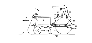
Referring to FIGs. 1 and 2, a work vehicle 2 (e. g.,
an agricultural tractor) includes a frame or chassis 4,
an operator's cab 6 supported above chassis 4, a seat or
dual seats 8 within cab 6, and a propulsion system 10 to
propel vehicle 2 along a ground surface 12 in a forward
direction 14. Propulsion system 10 includes an engine 16
secured to chassis 4, a transmission (not shown) coupled
to engine 16, two driven or non-driven front wheels 18
steered by a steering wheel 20, and two rear wheels 22
driven by engine 16 via the transmission. Brake pedals
24 located in cab 6 operate left and right service brakes
(not shown) to provide braking. Cab 6 is supported above
chassis 4 by an active cab suspension system (ACS) 26
including two front active vibration isolators 28 and 30
located on opposite sides of cab 6 and a rear isolator 32
centrally located at the rear of cab 6 between wheels 22.
The three-point suspension system provides stable control
of movement responsive to pitch, roll and bounce.
In some work vehicle applications, ACS 26 includes a
forward-looking sensor 34 mounted to vehicle 2 to detect
the bumpiness level on surface 12 forward of vehicle 2.
CA 02309740 2000-OS-10
WO 99/24309 PCTlUS98/21918
_ g _
Sensor 34 may include a radar to detect bumpiness based
on the time needed for electromagnetic signals to travel
from sensor 34 to surface 12 and be reflected back.
However, sensor 34 could also include a vision-based or
proximity sensor (e. g., a micropower impulse radar (MIR)
device). Sensor 34 is mounted to vehicle 2 at a location
oriented toward surface 12. For example, sensor 34 may
be mounted on the hood of vehicle 2 (34a), or mounted
below vehicle 2 to detect bumpiness forward of rear
wheels 22 (34b), or mounted forward of front wheels 18
(34c). The sensed signals represent general levels of
bumpiness (e. g., a smooth or rough surface) and are used
to adjust performance parameters of isolators 28-32.
In some work vehicle applications, ACS 26 includes a
leveling sensor 36 mounted to cab 6 to generate signals
indicative of the degree to which the attitude of cab 6
is level relative to horizontal. Leveling sensor 36 may
include a gyroscope or electronic Level signal generator,
and sensor 36 may be mounted at the center of gravity of
cab 6. The signal from sensor 36 can be used to control
the attitude of cab 6 and to maintain a level attitude.
ACS 26 may further include a movement sensor 37
(e.g., a three-axis accelerometer) mounted adjacent to an
operator's torso or head (e. g., supported by a headrest
of seat 8) to accurately sense the movement felt by the
operator. The signal from sensor 37 is used as a primary
or secondary control input to more accurately control the
movement of cab 6 and its affect on the operator. ACS 26
may also include several accelerometers mounted to cab 6.
These signals are combined to form a control input.
Components of other vehicle systems within cab 6 may
include a steering angle sensor 38 coupled to wheel 20 to
generate a signal representing steering angle, and brake
detecting circuits 39 coupled to brake pedals 24 to
detect application of the service brakes. Circuits 39
CA 02309740 2000-OS-10
WO 99/24309 PCT/US98/21918
- 10 -
can also be coupled directly to the brakes. The signals
generated by sensor 38 and circuits 39 are supplemental
control inputs used by ACS 26 to counteract movement of
cab 6 due to forces applied to chassis 4 when turning or
braking, or are used as preparatory signals (e.g., to
bias the hydraulic fluid supply toward the particular
isolator which will require the fluid).
As explained below, ACS 26 attenuates transmission
of vibrations between chassis 4 and cab 6 caused by the
interaction of wheels 18 and 22 with surface 12, or due
to forces applied to vehicle 2 during operation of other
vehicle systems such as the steering, transmission and
braking systems. Each isolator 28-32 can be controlled
separately, or coordinated with each other to improve
vibration isolation and to provide additional functions.
Coordinated control of isolators 28-32 can provide
improved response to pitch, roll and bounce forces
applied to cab 6. Performance parameters of ACS 26 are
adjustable in response to estimated conditions ahead of
vehicle 2, or to changes in load. The gain, and thus the
frequency response, of ACS 26 is set to maximize the
vibration isolation of ACS 26 without exceeding the
mechanical limits (i.e., actuator stroke) of the system.
The gain can further be tuned manually to account for
differences among the frequency response of individual
operators.
Although a tractor is shown in FIGS. 1 and 2, ACS 26
may be used with other agricultural work vehicles such as
combines or cotton-pickers or with construction vehicles
such as backhoes, cranes, dozers, trenchers, skid-steer
loaders, etc. These vehicles may be equipped with either
wheeled or tracked propulsion systems. Other
arrangements of ACS 26 can be used in these vehicles such
as a three-point active suspension system including one
front and two rear isolators or a four-point system with
two front and two rear isolators. Further, one or more
CA 02309740 2000-OS-10
WO 99/24309 PCTNS98/21918
- 11 -
active vibration isolators 28-32 can be mounted between
cab 6 and seat 8 in an active seat suspension system.
Referring to FIG. 3, front active vibration isolator
28, which is substantially the same as front isolator 30,
includes lower and upper mounts 40 and 42, respectively,
which are attached to chassis 4 and cab 6, respectively,
by welding, screws, bolts or other fasteners. A spring
44 including an air bag is connected between mounts 40
and 42 to support the static weight of cab 6. Spring 44
includes an enclosure 46 comprising a cylindrical outer
casing 48 attached (e.g., welded) to lower mount 40 and a
cylindrical inner casing 50 attached to upper mount 42
and extending into outer casing 48. The air bag (not
visible) is secured within enclosure 46. The air bag is
inflated with pressurized air through a supply tube 52
and a pneumatic fitting 54 to a pressure sufficient to
support the static weight of cab 6 so as to off-load the
weight from other components of isolator 28.
In some work vehicle applications, the air pressure
in springs 44 is set at a constant level to support the
static weight of cab 6, and the pressure is not adjusted
to account for changes in load of cab 6 on isolators 28-
32. In such applications, a pneumatic system is charged
with pressurized air supplied to spring 44 through tube
52. The pressure of the air supplied to spring 44 is set
or regulated at or slightly below the pressure needed to
raise cab 6. Solenoid-controlled valves turn on the flow
of air to isolators 28-32. Such systems may be
pressurized off-line so the vehicle does not require an
on-board air compressor. Alternatively, air pressure in
such pneumatic systems may be maintained by an on-board
air compressor to replace air lost to leaks. This type
of system does not actively control air pressure, and
does not respond to changes in the weight of cab 6.
CA 02309740 2000-OS-10
WO 99lZ4309 PCfNS98l21918
- 12 -
However, in other work vehicle applications, ACS 26
actively controls the air pressure within springs 44. As
described below, such systems include air control valves
to selectively supply and relieve pressurized air from a
source (e. g., a compressor and/or high pressure air tank)
to springs 44 in response to control signals generated
based on, for example, load forces exerted on springs 44
by cab 6. The compressed air source provides the ability
to actively control pressure during operation of vehicle
2. To improve accuracy in controlling pressure, the
pressure in springs 44 may be monitored using a pressure
sensor 56 mounted to upper mount 42 and configured to
generate closed-loop pressure feedback signals on
conductors 58.
Isolator 28 includes a rollover restraint system 60
to prevent cab 6 from detaching from chassis 4 during a
rollover. Restraint system 60 includes a rollover frame
62 secured (e. g., welded) to lower mount 40 which is able
to cooperate with a plate 64 secured to outer casing 48.
Frame 62 includes a circular hole 66 having a diameter
slightly larger than that of casing 48 but less than that
of plate 64. In the event of a rollover causing casing
48 to separate from lower mount 40, casing 48 can slide
upward within hole 66 until plate 64 makes contact with
frame 62. Thus, movement of cab 6 caused by a rollover
is restrained and cab 6 does not detach from chassis 4.
Connected adjacent to spring 44 between mounts 40
and 42 is a linear hydraulic actuator 68. Actuator 68
includes a cylinder 70 and a piston or rod 72 moveable
therein to move cab 6 relative to chassis 4. A valve
assembly 74 coupled to cylinder 70 selectively supplies
and relieves pressurized hydraulic fluid between a pair
of tubes 76 and 78 and cylinder 70 in response to valve
control signals received on conductors 80. Thus, piston
72 moves in either direction along the axis of cylinder
70 in response to the control signals. Preferably, the
CA 02309740 2000-OS-10
WO 99124309 PCTNS98/21918
- 13 -
control signals are pulse-width modulated (PWM) control
signals and valve assembly 74 is a four-way, three-
position electrically-controlled solenoid valve.
Referring to FIGS. 3-5, a threaded free end 82 of
piston 72 extends through upper mount 42 and is coupled
to a movement sensor 84 via a mounting assembly 86 which
provides high-frequency isolation of sensor 84 from mount
42. In upward order, assembly 86 includes an internally-
threaded rod nut 88 for receiving end 82, a potentiometer
target bracket 90 having an aperture 92, a lower hardened
washer 94 having an aperture 96, an elastomeric vibration
isolator 97 having lower and upper isolator portions 98
and 100 located on opposite sides of upper mount 42 and
having apertures 102 and 104, an upper hardened washer
106 having an aperture 108, and a bolt/sleeve 110 having
a threaded bore 112 to securely receive free end 82 of
piston 72. Isolator portions 98 and 100 include inner
annular portions 114 and 116, respectively, which pass
through an aperture 118 in mount 42. The components of
assembly 86 are coaxially aligned such that piston 72
passes through nut 88, apertures 92, 96, 102, 118, 104
and 108 and bore 112. Thus, elastomeric vibration
isolator 97 physically separates upper mount 42 from
piston 72 to provide high-frequency isolation.
Bolt/sleeve 110 includes a tapped hole 120 coaxial
to piston 72 to receive a threaded post 122 of movement
sensor 84, thereby securely mounting sensor 84 to piston
72. Sensor 84 generates an electrical signal on
conductors 124 which represents movement of piston 72 in
a direction along the axis of piston 72 at a point P
(e.g., at washer 94) lying between actuator 68 and
elastomeric isolator 97. Thus, isolator 97 provides
high-frequency isolation between upper mount 42 and
movement sensor 84. Sensor 84 preferably includes an
accelerometer. During operation, valve control signals
generated in response to the signals from sensor 84 are
CA 02309740 2000-OS-10
WO 99/24309 PCT/US98n1918
- 14 -
applied to actuator 68 to move cab 6 to counteract the
movement of chassis 4. Post 122 can alternatively be
secured directly to a bore in end 82 of piston 72.
Potentiometer target bracket 90 includes first and
second flat portions 126 and 128 and a rising portion 130
extending from portion 126 to 128. A displacement sensor
132 (e. g., potentiometer; inductive sensor) is adjustably
secured by bolts 134 to a track 136 running along valve
assembly 74. Sensor 132 generates electrical signals on
conductors 138 representing the distance that actuator
shaft 140 extends from casing 142. This distance is
indicative of the displacement between mounts 40 and 42.
The displacement signal from sensor 132 is used to bias
piston 72 to a centered steady-state position so as to
prevent migration to either end of cylinder 70 over time,
and to control the height of cab 6 above chassis 4.
Vibration isolator 28 may also include a load sensor
144 which generates electrical signals on conductors 146
representing load forces exerted by cab 6 on chassis 4.
The load forces can be used to adjust air pressure within
spring 44 to account for changes in weight of cab 6. For
example, changes in the weight of an operator, or changes
due to having two people in cab 6, can be accommodated.
To accommodate translational movement between
chassis 4 and cab 6, a spherical bearing assembly 148 is
provided between cylinder 68 and lower mount 40.
Assembly 148 includes a bearing eye 150 which extends
down from cylinder 68 and encompasses a spherical bearing
152. Eye 150 fits into a slot within a bearing block 154
mounted to lower mount 40, and is held in place by a
crosspin 156 inserted through an aperture in block 154
and bearing 152. Assembly 148 allows relative movement
of cylinder 68 about the axis of bearing 152.
CA 02309740 2000-OS-10
WO 99/24309 PCT/US98/Z1918
- 15 - ,
Although FIG. 3 shows actuator 68 adjacent to spring
44, actuator 68 and spring 44 may be coaxially located as
shown in U.S. Pat. No. 5,603,387, herein incorporated by
reference in its entirety.
Referring to FIG. 6, rear isolator 32 is similar to
front isolator 28 except that rear isolator 32 includes a
second spring 44 to off-load the higher static weight of
cab 6 on rear isolator 32. Off-loading may be necessary
to avoid exceeding the weight capacity of a single air
bag. However, a second spring may not be needed if ACS
26 includes four active isolators, or if the cab weight
does not exceed the capacity of a single air bag. Other
differences between rear isolator 32 and front isolator
28 include the shapes of potentiometer target bracket 90
and of upper mount 42 (which both extend between springs
44), and the coupling of elastomeric vibration isolator
97 to bracket 90 instead of to upper mount 42. Sensor
132 is mounted on or within cylinder 70 such that sensor
132 and cylinder 70 are co-linear.
Referring to FIG. 7, each vibration isolator 28-32
is represented by a mechanical schematic showing spring
44 connected between cab 6 and chassis 4, actuator 68
connected between chassis 4 and point P (e. g., at washer
94), and elastomeric vibration isolator 97 in series with
actuator 68 between point P and cab 6. Actuator 68
provides low frequency (e. g., below 20 Hz) isolation
between chassis 4 and point P. Isolator 97 provides high
frequency (e.g., above 20 Hz) isolation between point P
and cab 6. Thus, cab 6 is isolated from chassis 4 for
both high and low frequency movement or vibrations.
Each individual active vibration isolator 28-32 has
characteristics defined by the mass M of cab 6 supported
by the isolator, the stiffness K9 of spring 44, the input
velocity V~ of actuator 68, and stiffness K and damping
coefficient R of isolator 97. Stiffness KS of spring 44
CA 02309740 2000-OS-10
WO 99/24309 PCT/US98/21918
- 16 -
affects only the power consumption of actuator 68 and
does not affect idealized isolation. The quantity being
actively controlled is input velocity V~ of actuator 68.
Referring to FIG. 8, ACS 26 includes front isolators
28 and 30, rear isolator 32, an active suspension system
controller (ASC) 200, a source of pressurized hydraulic
fluid 202, a pressurized air source 204, an air control
valve-206 fox each isolator 28-32, and a vehicle data bus
208. ASC 200 is connected by electrical conductors to
movement sensor 84, displacement sensor 132, load sensor
144, air pressure sensor 56, valve assembly 74, and air
control valve 206 of each isolator 28-32, and to bump
sensor 34, leveling sensor 36, and movement sensor 37.
ASC 200 receives signals from each sensor and generates
output signals in response thereto which are applied to
valves 74 and 206. ASC 200 further communicates to and
from other vehicle systems via bus 208. Preferably, bus
208 conforms to the SAE J-1939 standard for vehicle data
busses entitled "Recommended Practice for a Serial
Control and Communications Vehicle Network".
Pressurized hydraulic fluid source 202 includes an
engine-driven pump 210 to supply pressurized hydraulic
fluid to isolators 28-32 via tubes 76 under the control
of valve assemblies 74. Valve assemblies 74 also control
release of fluid from isolators 28-32. Released fluid is
returned to a reservoir 212 of source 202 via tubes 78.
When pressure in springs 44 is actively controlled,
each air control valve 206 includes an apply valve 214
which receives a flow of pressurized air from source 204
(e.g., a compressor) and selectively applies the flow to
spring 44 of each isolator 28-32 in response to control
signals generated by ASC 200. Each valve 206 includes a
release valve 216 to selectively release air from the air
bag to a vent 218 in response to the air control signals.
The pressure within each air bag increases up to the
CA 02309740 2000-OS-10
WO 99/24309 PGT/US98/21918
- 17 -
maximum pressure of source 204 when the apply valve 214
is open, and decreases when release valve 216 is open.
The air control signals may include PWM signals.
Referring to FIG. 9, ASC 200 includes a signal
conditioning/multiplexer circuit 220 to receive signals
from sensors 84, 132, 144 and 56 of each isolator 28-32
and from sensors 34, 36 and 37.~ ASC 200 further includes
an active suspension control circuit (ASCC) 222 coupled
to circuit 220, a memory circuit 224 accessible to ASCC
222, an interface circuit 226 to generate control signals
(e. g., PWM signals) to valve assembly 74 and air control
valve 206 associated with each isolator 28-32, and a data
bus interface circuit 228 configured to communicate with
other vehicle systems across bus 208.
Circuit 220 includes signal conditioning hardware
(e. g., filters), multiplexers and A/D interface circuits.
ASCC 222 includes a digital processor (e.g., a 16-bit
microprocessor) which may include software conditioning
such as digital filtering or averaging. Memory circuit
224 includes nonvolatile memory (ROM, EEPROM or FLASH)
for storing programs and volatile memory (RAM) for
storing variables. Dedicated, specific purpose equipment
or hard-wired logic circuitry can also be used. PWM
interface circuit 226 generates PWM control signals based
upon digital words written to circuit 226 by ASCC 222.
Interface circuit 228 formats input and output bus
messages which conform to the J-1939 standard protocol.
ASC 200 includes an operator interface circuit to
receive command signals from operator-actuatable command
devices and control operation of ACS 26. The interface
includes a signal conditioning/multiplexer circuit 230
(which may be the same as circuit 220) which receives
signals from command devices 232-238. Devices 232-238
include any or all of: a cab rate command device 232
(e. g., potentiometer) to set a rate at which cab 6 moves
CA 02309740 2000-OS-10
wo ~n~o9 pcrius9sni9is
- is -
during power-up/power-down; a cab height command device
234 (e.g., potentiometer) to set a steady-state height of
cab 6 above chassis 4; a cab lower command device 236
(e.g., switch) to command cab 6 to a minimum height; and
a tuning device 238 (e.g., potentiometer) to tune the
gain, and thus the frequency response, of ACS 26.
Referring to FIG. 10, ASC 200 generates the valve
control signals applied to actuator 68 via conductors 80
for each active vibration isolator 28-32. The control
signals may be generated individually for each isolator
28-32 using the process shown in FIG. 10. The inputs to
the process are displacement signal D (FIG. 7) sensed by
sensor 132, and acceleration signal A (FIG. 7) sensed by
sensor 84. A first network 240 having the shown transfer
characteristics removes a DC component of signal A caused
by the acceleration of gravity and integrates signal A to
generate a signal representing absolute velocity at point
P (FIG. 7). A second network 242 provides dynamics to
isolate lower vibration frequencies (e.g., below 20 Hz)
with desired stability and performance characteristics.
Second network 242 can be tuned to the resonant frequency
of chassis 4, or to a frequency selected by the operator.
A summing circuit 244 sums the output from network 242
with signal D to produce a combined signal representing
both the velocity of chassis 4 to be counteracted and the
displacement of piston 72. Signal D causes piston 72 to
return to a centered steady-state position to prevent the
migration of piston 72 to either end of cylinder 70 over
time. A gain circuit 246 amplifies the summed signal and
applies the amplified signal to PWM interface circuit 226
to generate the valve control signals applied to
hydraulic valve 74. Valve 74 responds by selectively
supplying and relieving hydraulic fluid to each actuator
68 to cause each piston 72 to move cab 6 relative to
chassis 4.
CA 02309740 2000-OS-10
WO 99124309 PCT/US98/21918
- 19 -
Thus, the transmissibility of each isolator 28-32 is
defined by the equation:
Vo/VI = 1/ (1+G} * ( (R/M) s + K/M) / (s2 + (K/M) s + K/M)
wherein G is the gain (e. g., 100) of circuit 246 relating
input velocity V~ of actuator 68 with the velocity at
point P, Vo is the velocity of cab 6 (FIG. 7) , VI is the
velocity of chassis 4 (FIG. 7), R and K are the damping
coefficient and stiffness of elastomeric isolator 97, and
M is the mass of cab 6 being supported. The gain G of
circuit 246 may be adjusted manually by an input device
such as a potentiometer (not shown), or automatically as
described below. Stiffness KS of spring 44 does not
affect transmissibility because spring 44 only off-loads
the static weight of cab 6 to reduce power consumption.
In work vehicle applications wherein air pressure
within air springs 44 is actively controlled, ASC 200
generates the control signals applied to the air control
valve 206 of each isolator 28-32 to selectively supply
and relieve pressurized air to the air bags. The control
signals control the air pressure within springs 44 in
response to load signals generated by load sensors 144.
The pressure within springs 44 is controlled to support
the static weight of cab 6 on each isolator 28-32. Thus,
changes in weight of cab 6 at each support position are
accommodated by changes in pressure within each spring
44. Closed-loop pressure control can be provided using
pressure signals from sensors 56 as feedback signals.
The control process shown in FIG. 10 and the active
control of pressure within springs 44 can be modified to
adjust performance parameters of ACS 26. The adjustable
parameters include, for example, the gain and frequency
response of isolators 28-32, and the gain at which the
displacement signal from sensor 132 biases piston 72 to
the steady-state position to prevent migration of piston
CA 02309740 2000-OS-10
WO 99/Z4309 PCT/US98/Z1918
- 20 -
72 to either end of cylinder 70 over time. The gain of
isolators 28-32 is adjusted by changing gain G of circuit
246, or the gain of network 240 or 242 (e. g., gain G1).
The frequency response is adjusted by modifying the
transfer function of network 242. The gain at which
piston 72 is biased is adjusted by changing the impact of
signal D in the control process of FIG. 10. For example,
the impact is changed by adjusting the weight of signal D
. in the combined signal output by summing circuit 244. As
discussed above, the pressure within springs 44 is also
an adjustable parameter which can be actively controlled.
The primary control inputs for ACS 26 include the
acceleration signal A and displacement signal D. The
system is set to provide maximum gain without exceeding
the stroke of actuators 68. However, the gain may then
be adjusted based on secondary or supplemental control
inputs such as estimated conditions or signals from other
vehicle systems. One supplemental input used to adjust
the performance parameters of ACS 26 is the estimated
condition of surface 12 forward of vehicle 2. Adaptive
or predictive control algorithms respond to the estimated
condition to improve performance. For example, the
performance parameters may be adjusted based upon the
estimated bumpiness of surface 12 ahead of vehicle 2.
Bumpiness may be estimated by processing (e.g., taking a
root-mean-square of) the signals from bump sensor 34.
Alternatively,.the bumpiness level can be estimated from
the previous level of movement sensed by movement sensor
84 based upon the assumption that surface 12 forward of
vehicle 2 will have a similar bumpiness level as surface
12 behind vehicle 2.
The bumpiness level can also be estimated based upon
the assumptions that vehicle 2 travels quickly on roads
and slowly in fields, and that roads are smooth while
fields are bumpy. The level is estimated by comparing
ground speed of vehicle 2 to a predetermined threshold
CA 02309740 2000-OS-10
WO 99/24309 PCT/US98/21918
- 21 -
speed (e.g., 10 mph). High velocities correspond to a
smooth bumpiness level, while low velocities correspond
to a rough bumpiness level. Other methods of estimating
bumpiness based upon the positions of vehicle 2 and geo-
referenced maps of surface 12 are described below.
When the estimated signals represent a bumpiness
level, the valve control signals applied to actuator 68
attenuate movement of cab 6 due to movement of chassis 4
in response to the bumpiness level by adjusting the gain
of ACS 26. If surface 12 has a high bumpiness level, ASC
200 lowers the gain G of circuit 246 such that piston 72
is not commanded beyond its maximum stroke. However, if
surface 12 has a low bumpiness level, ASC 200 raises the
gain G to increase isolation provided by isolators 28-32.
The degree at which gain is adjusted may depend upon the
level of bumpiness if there are more than two levels.
The gain at which the sensed displacement causes cab
6 to move toward the centered steady-state position can
be decreased when surface 12 is relatively bumpy to help
insure that piston 72 has sufficient stroke to respond to
the bumps as they occur. This gain may be increased when
surface 12 is smooth to provide a smoother ride. Also,
the frequency response of isolators 28-32 may be changed
based on estimated bumpiness if empirical tests indicate
that such an adjustment would increase ride quality. The
frequency response may also be adjusted manually by the
operator using signals from tuning device 238.
ASC 200 can control each active vibration isolator
28-32 independently. Independent control, however, does
not provide functions which are achieved or optimized
only through coordinated control. Thus, the valve
control signals applied to actuators 68 and air control
signals applied to air control valves 206 are coordinated
with each other to coordinate control of isolators 28-32.
CA 02309740 2000-OS-10
WO 99/24309 PCT/US98/21918
- 22 -
In some work vehicle applications, the valve control
signals applied to actuators 68 are coordinated with each
other to coordinate control of the displacements between
chassis 4 and cab 6 at the locations of isolators 28-32.
A benefit of coordinating the displacements can be seen,
for example, during power-up and power-down of vehicle 2.
Assume that actuator 68 of-each isolator 28-32 is
controlled using an independent controller. At power-up,
the static weight of cab 6 is just supported by springs
44 and pistons 72 are in their power-down positions (eg.,
maximum downward or retracted positions). Then, as each
independent controller enters an actuator control loop
after completing initialization logic (e.g., built-in
tests), the valve control signals cause each actuator 68
to raise cab 6 until each respective piston 72 reaches an
operating position (e. g., its centered steady-state
position). Each actuator 68 will raise cab 6 with random
timing and rates compared to other actuators 68 due to
differences in timing for each controller to enter its
actuator control loop, and differences in timing for the
vehicle hydraulic system to provide pressurized hydraulic
fluid to each actuator 68. The random timing and rates
with which cab 6 is raised on power-up causes jerking and
uneven cab attitudes which are felt by the operator. A
similar problem occurs during power-down of vehicle 2.
In response to these problems, ASC 200 coordinates
control signals applied to each isolator 28-32 to control
the attitude and movement rate of cab 6 during power-up
and power-down. At power-up, ASC 200 performs built-in
tests and other initialization functions. Then, ASC 200
raises cab 6 to a steady-state height while maintaining
cab 6 at a substantially constant or level attitude by
coordinating the command signals applied to valves 74 and
using sensed displacement signals as closed-loop feedback
signals. Equalized commands are simultaneously applied
to valves 74 to extend each piston 72 from its power-down
CA 02309740 2000-OS-10
WO 99/24309 PGT/US98/Z1918
- 23 -
position to its steady-state position at a predetermined
rate. The rate can be fixed, or can be manually set by
cab rate command device 232. To insure availability of
sufficient hydraulic power to each isolator 28-32, ASC
200 delays extending pistons 72 until a sufficient time
has passed following power-up. Alternatively, ASC 200
can monitor the displacement of each isolator 28-32 and
set the command signals to extend pistons 72 no faster
than the movement of the slowest isolator 28-32. Thus,
no isolator is raised faster than another isolator which
may lag due to insufficient hydraulic power. Closed-loop
displacement control is also performed during power-down.
In one embodiment, ASC 200 includes control logic
which prevents cab 6 from being actively moved relative
to chassis 4 when vehicle 2 is not moving (i.e., ground
velocity less than a predetermined speed threshold) or
when an operator-presence sensor indicates the operator
is not present. For example, ASC 200 does not raise cab
6 to its steady-state height until vehicle speed exceeds
a threshold. Gating the valve control signals with
movement of vehicle 2 prevents the unexpected movement of
cab 6 when a person outside cab 6 is nearby. Vehicle
speed can be sensed using sensor 338 (FIG. 12).
Another benefit of coordinating the displacements is
the ability to control the attitude of cab 6, either with
respect to the horizontal (i.e., horizon) or with respect
to chassis 4. For example, to maintain a level attitude
of cab 6 with respect to chassis 4, displacement signals
from each sensor 132 can be combined (e.g., averaged) and
the combined signal used as the steady-state displacement
control parameter (e. g., D in FIG. 10). Further, if work
vehicle 2 is equipped with leveling sensor 36, the
steady-state displacement control parameter can depend on
the signal from sensor 36 to maintain a level attitude of
cab 6 with respect to the horizontal. For example, if a
sensed signal indicates that the front of cab 6 is
CA 02309740 2000-OS-10
WO 99/24309 PCTNS98/21918
- 24 -
tilting downward, the displacement of front isolators 28-
30 can be increased and the displacement of rear isolator
32 decreased to level the attitude of cab 5. Sideways
adjustments can be made when cab 6 is tilting sideways.
The changes to the steady-state displacements that are
made to control the attitude of cab 6 are limited to a
portion of the stroke of piston 72 such that piston 72
retains the ability to provide vibration isolation.
The steady-state height of cab 6 above chassis 4 can
also be adjusted manually using cab height command device
234. Further, the height of cab 6 can be lowered to a
minimum level in response to an actuation of lower
command device 236 (for example, to decrease the
clearance required for vehicle 2 to pass beneath an
overhang).
The valve control signals may also be coordinated
with each other to coordinate the attenuated transmission
of force between cab 6 and chassis 4. For example, as
explained above, the performance parameters of isolators
28-32 may be adjusted during operation of vehicle 2. It
may, however, be undesirable for each isolator 28-32 to
have different parameter values. Thus, the parameters of
each isolator 28-32 may be adjusted to the same parameter
values by, for example, averaging the individually-
determined parameter values for each isolator 28-32.
In some work vehicle applications, the control
signals applied to air control valves 206 are coordinated
with each other to coordinate control of air springs 44.
As described above, the air pressure within each spring
44 can be actively controlled to just support the static
weight of cab 6 on each isolator 28-32 so that actuators
68 are able to move cab 6 with minimal power consumption.
However, the total weight of cab 6 may change due to, for
example, changes in weight of the operator or operators,
or storage or removal of objects (e. g., tools). Further,
CA 02309740 2000-OS-10
WO 99/24309 PCT/US98JZ191$
- 25 -
even assuming a constant total cab weight, the relative
weight of cab 6 on isolators 28-32 depends on the slope
of surface 12, regardless of whether vehicle 2 is still
or is moving. For example, when vehicle 2 is on a slope,
the weight supported by a downward isolator increases and
the weight supported by an upward isolator decreases.
Without adjustment, the air pressure in each spring 44
will no, longer be correct, and actuator 68 will consume
extra power to counteract the changed effective weight.
Changes in load force exerted on each isolator 28-32
due to a change in total weight of cab 6 are accommodated
by sensing load force on each isolator 28-32, summing the
signals to determine a total load force, and distributing
the total load force among isolators 28-32 using a known
formula based upon the configuration of isolators 28-32.
For example, if total load force corresponds to a weight
of 2000 pounds, ASC 200 may attribute 500 pounds to each
front isolator 28-30 and 1000 pounds to rear isolator 32.
The air pressure in the respective springs 44 would then
be set to support these weights. Thus, the load forces
will. be distributed correctly even if vehicle 2 is on a
steep grade when the measurements of load force are taken
(which would cause incorrect results if the air pressure
of each isolator 28-32 was set independently based upon
the sensed load force of that isolator). Total load
force is preferably sensed when vehicle 2 is still (e. g.,
at power-on or when vehicle velocity is 0) to prevent
movements of cab 6 from affecting the sensed signals.
Changes in the relative weight of cab 6 on each
isolator due to changes in ground slope during operation
are accommodated by distributing the total load force of
cab 6 (determined on power-on or when vehicle velocity is
0) to isolators 28-32 in one of two manners. (Note that
the absolute load signals generated by sensors 144 may be
inaccurate when vehicle 2 is moving.) First, the total
load force can be distributed among isolators 28-32 based
CA 02309740 2000-OS-10
WO 99/Z4309 PCT/US98/21918
- 26 -
on the attitude of cab 6 sensed by leveling sensor 36.
For example, if the front of cab 6 is tilted downward,
the air pressure in front isolators 28-30 is increased
and the air pressure in rear isolator 32 is decreased.
Second, the load signals from isolators 28-32 can be
summed and the total load force (measured when vehicle 2
was still) distributed to each isolator 28-32 based upon
the relative contribution to the summed signal of that
isolator's load signal. The air control signals for each
isolator 28-32 are then generated based upon the
distributed load force.
Thus, by coordinating the air control signals to
distribute the total load force among isolators 28-32,
changes in weight of cab 6 are accommodated accurately
even when vehicle 2 is on a sloped surface or moving.
When work vehicle 2 is equipped with a vehicle data
bus, ACS 26 communicates via the bus with other vehicle
systems having parameters related to forces which will be
applied or are being applied to vehicle 2. Movement of
cab 6 due to such forces is attenuated by appropriate
control of isolators 28-32 as explained below. Control
input signals from such other vehicle systems are
supplemental inputs for ACS 26, and the acceleration
signals remain the primary control inputs.
Referring to FIG. 11, an exemplary vehicle control
system 250 shows vehicle 2 equipped with ASC 200 and with
other vehicle control systems in communication with each
other via bus 208. Vehicle control system 250 includes
an armrest console control system 252 coupled to armrest
console input devices 254 to receive command signals, and
a positioning control system 256 to receive positioning
signals representing locations of vehicle 2. Although
command devices 232-238 are wired to ASC 200 in FIG. 9,
these command devices may also be located in the armrest
console where they are read by control system 252.
CA 02309740 2000-OS-10
WO 99/24309 PCT/US98/21918
- 27 -
Control system 250 includes other vehicle systems
having parameters related to forces applied to vehicle
10. For example, control system 250 may include a tool
height control system 258, a steering control system 260,
a four-wheel drive/differential lock (4WD/DL) control
system 262, and a transmission and speed control system
264. Each system 258-264 includes input devices 266 to
generate command signals and output interfaces 268 to
control output actuators. Vehicle 2 may be equipped with
any or all of these systems (e. g., a tractor equipped
with tool height control system 258 may not have an
armrest control console coupled to bus 208). Vehicle 2
may also include other vehicle systems having parameters
related to forces applied to vehicle 2. Communication of
parameters related to forces applied to vehicle 2 across
bus 208 gives ASC 200 access to such parameters without
the need for separate sensors dedicated to ACS 26.
In one embodiment, tool height control system 258 is
installed on a tractor equipped with a hitch assembly to
raise and lower a tool (e. g., implement or plow). Input
devices 266 include draft force and position command
devices used by control system 258 to generate control
signals applied to an actuator to raise and lower the
tool. Sensors provide draft force and position feedback
signals. The command signals generated by input devices
266 are indicative of draft forces which will be applied
to the tractor, and the feedback signals are indicative
of draft forces currently being applied to the tractor.
Thus, the command signals and feedback signals are both
related to draft forces applied to the tractor. A hitch
assembly control system for a tractor having the above
components is described in U.S. Pat. No. 5,421,416. In
another embodiment, tool height control system 258 is
installed on a combine equipped with a positioning
assembly which raises and lowers a header. A header
control system for a combine is described in U.S. Pat.
CA 02309740 2000-OS-10
WO 99/Z4309 PGT/US98~21918
- 28 -
No. 5,455,769. The '416 and '769 patents are commonly
assigned and herein incorporated by reference.
Steering control system 260 includes a steering
input device 266 (e.g., steering wheel 20) coupled to a
sensor (e. g., sensor 38) which generates steering angle
command signals indicating the degree of turning. A
feedback sensor can be used to measure actual turning.
The sensed signals are indicative of the normal forces
applied to vehicle 10 due to turning since steering angle
is a measure of turning radius, and normal force equals
velocity squared divided by radius. Velocity is sensed
by a ground speed sensor such as sensor 338. A steering
control system is disclosed in U.S. Pat. No. 5,194,851,
commonly assigned and herein incorporated by reference.
An exemplary 4WD/DL control system 262 is described
in U.S. Pat. No. 5,505,267, commonly assigned and herein
incorporated by reference. Control system 262 includes
4WD/DL input devices 266 and output interfaces 268, and
has parameters indicative of command and output signals
for a 4WD clutch and DL lock related to forces applied to
vehicle 2 as 4WD is engaged and disengaged and DL is
locked and unlocked. The '267 patent further discloses
brake detecting circuits (e.g., circuits 39) coupled to
the brakes (e. g., brakes 24) of a vehicle to generate
signals representing the state of the brakes and, thus,
whether braking forces are being applied to vehicle 2.
An exemplary transmission/speed control system 264
is described in U.S. Pat. No. 5,233,525, also commonly
assigned and incorporated herein by reference. Control
system 264 includes gear shift and speed input devices
266 and output interfaces 268. Control system 264 has
parameters indicative of commanded and output gear shift
signals of a transmission, and commanded and output speed
actuator settings. These parameters are related to the
CA 02309740 2000-OS-10
WO 99/24309 PCT/US98~21918
- 29 -
forces applied to vehicle 2 as the transmission upshifts
and downshifts and vehicle 2 accelerates and decelerates.
ASC 200 has access via bus 208 to parameters of the
other systems shown in FIG. 11 related to forces applied
to vehicle 2 during operation of those systems. ASC 200
uses the parameters as supplemental control inputs when
generating control signals for isolators 28-32 to
attenuate movement of cab 6 due to such forces. For
example, if a parameter indicates that a pitch or normal
force is about to be applied to vehicle 2 control signals
applied to isolators 28-32 will prevent the operator from
being thrown backwards or sideways. The gain parameter
can also be adjusted when such forces are predicted.
Further, the attitude of cab 6 can be changed to improve
ride quality in response to such forces (e. g., by tilting
cab 6 into a turn, or tilting cab 6 in the fore-and-aft
direction in response to a pitch force). In addition,
the force parameters from other vehicle systems can be
used by ACS 26 as preparatory signals. For example, ACS
26 could bias the oil supply to the isolator 28-32 which
will require the most oil flow when the force actually
impacts cab 6. Adaptive or predictive control algorithms
can use the parameters to predict movement of cab 6
caused by the forces. Fuzzy logic control algorithms may
also be used to generate control signals in response to
the force parameters to provide improved ride quality.
Empirical testing may be used to determine the control
algorithms.
Referring to FIG. 12, positioning control system 258
includes a positioning control circuit (PCC) 300 for
receiving, processing and communicating site-specific
data. PCC 300 is coupled to an interface circuit 302 for
communicating across bus 208. PCC 300 also communicates
with external systems such as a computer 304 via a memory
card 306 which transfers geo-referenced maps including
.spatially-variable map data indicative of fields, roads
CA 02309740 2000-OS-10
WO 99/24309 PCT/US98I21918
- 30 -
and the bumpiness thereof. Card 306 can be a Type II
PCMCIA card made by Centennial Technologies, Inc. PCC
300 includes a digital processor and memory. However,
dedicated, specific purpose equipment or hard-wired logic
circuitry can also be used.
PCC 300 communicates with an operator through a user
interface 308 via a bus 310 (e. g., RS-232/485 interface).
Interface 308 can include, for example, a graphical user
interface 312 providing cursor control (e. g., a mouse,
joystick or four-way switch), assignable switches 314
(e. g., push buttons) configurable by PCC 300, a keyboard
316 and a voice interface 318. PCC 300 generates display
signals applied to a reconfigurable display 320 (e. g.,
CRT, flat screen active-matrix LCD) via a bus 322.
Display 320 can display, inter alia, the configuration of
switches 314. User interface 308 and display 320 are
located in cab 14 for easy operator access. PCC 300 may
communicate with a printer 324 via an interface 326
(e. g., an RS-232 link).
PCC 300 also communicates with a location signal
generation circuit 328 which generates location signals
representing the positions of vehicle 2. Circuit 328
includes a global positioning system (GPS) receiver 330
with an associated antenna 332, and a differential GPS
(DGPS) receiver 334 with an associated antenna 336. A
single antenna may be used in place of antennas 332 and
336. GPS receiver 330 may be made by Trimble Navigation
Ltd. of California, and DGPS receiver 334 may be made by
Satloc, Inc. of Arizona. GPS receiver 330 determines
longitude and latitude coordinates (and altitude) of the
vehicle from signals transmitted by the GPS satellite
network. Accuracy of the position data is improved by
applying correction signals received by DGPS receiver
334. In one embodiment, PCC 300 interfaces with the
SATLOC L-Band Integrated TerraStar DGPS System via an RS-
485 link.
CA 02309740 2000-OS-10
WO 99/24309 PCTNS98/21918
- 31 -
PCC 300 receives signals representing the ground
speed of vehicle 2 from ground speed sensor 338 via
interface 340 (e. g., a frequency interface). Ground
speed sensor 338 preferably includes a radar device
mounted to the body of vehicle 2. However, sensor 338
may also include a magnetic pickup sensor configured to
sense the speed of the vehicle's wheels or transmission.
Referring to FIG. 13, bumpiness level data used to
adjust the performance parameters of ACS 26 may also be
determined using vehicle position as an index to geo-
referenced maps of surface 12. For example, PCC 300 is
provided with predetermined geo-referenced maps or data
layers 350 stored on memory card 306. Map 350 is
represented by a table wherein rows represent field
locations and columns represent the longitude and
latitude coordinates, altitude and the bumpiness level
for each location. In one embodiment, bumpiness levels
are represented using discrete numbers (e.g., level 1 = a
relatively smooth surface, level 2 - a medium surface,
level 3 - relatively bumpy surface). Other levels may
also be defined and real numbers may be used. For
example, data point no. 3 indicates that the altitude is
801.0 feet and the surface is relatively smooth at the
location defined by latitude and longitude coordinates -
88.7290720 and 39.0710740, respectively. Map 350 is
preferably implemented using a geographical information
systems (GIS) database stored as a DOS file on card 306.
Referring to FIG. 14, a predetermined geo-referenced
map 350 of a road 352 and a field 354 which includes
bumpiness level data is represented graphically. Road
352 is labeled bumpiness level 1 since it is relatively
smooth. One area of field 354 is labeled level 2 since
it has medium bumpiness, while a second area 358 of field
354 (i.e., area within the polygon) is labeled as level 3
since it is relatively bumpy. The bumpiness level data
stored in map 350 may have been generating during a
CA 02309740 2000-OS-10
WO 99124309 PGT/US98/21918
- 32 -
previous pass of vehicle 2 by storing the signals that
were generated by movement sensors 84 (using appropriate
filtering). Alternatively, scouting data may have been
entered into map 350 using computer 304, or map 350 may
distinguish only between smooth areas (e. g., paved roads)
and bumpy areas (e. g., fields) in which case bumpiness
level data is not needed if it is assumed that roads are
smooth and fields are bumpy.
When the vehicle and implement are at positions
shown by markers 360 and 362, the vehicle is on road 352
and the expected course of travel shown by arrows 364
indicates that the vehicle is expected to turn into field
354. The current bumpiness level is level 1, and a
bumpiness level of 2 is expected after the turn.
Similarly, when the vehicle and implement are located at
positions shown by markers 366 and 368, the vehicle is in
the smoother area of field 354 (level 2) and is about to
enter the bumpy area (level 3). PCC 300 can use the
current position of the vehicle and geo-referenced map
350 to estimate the bumpiness level that the vehicle will
encounter and to adjust the performance parameters of ACS
26 to accommodate changes in the level of bumpiness.
Referring to FIG. 15, vehicle 2 is equipped with
another embodiment of an active suspension system which
includes an active vibration isolator 400 mounted between
a side 402 of. cab 6 and a support member 404 extending
from chassis 4. Active or passive isolators or supports
406 between cab 6 and chassis 4 allow the cab to move in
response to actuations of isolator 400.
Isolator 400 may be the same as isolator 28. Since
isolator 400 no longer supports the static weight of cab
6, however, spring 44 may be eliminated or have a reduced
weight capacity. Eliminating spring 44 eliminates the
need for a compressed air source, reduces power used by
the system, and reduces cast. To maximize response to
CA 02309740 2000-OS-10
WO 99/Z4309 PCT/US98/21918
- 33 -
cab pitch, isolator 400 is mounted high on side 402 of
cab 6. Member 404 may be an engine compartment wall or
another vertical support structure securely mounted to
chassis 4. Alternatively, member 404 could be oriented
along the longitudinal direction of vehicle 2 such that
the system is responsive to roll. Isolators 406 may be
existing cab mounts. Multiple isolators 400 may be used
on side 402 of cab 6 to provide isolation in other axis'
such as that provided by bottom-mounted isolators 28-32.
Isolator 400 provides control in the longitudinal
direction. However, active isolators can also be mounted
so as to control movement of cab 6 in the six degrees of
freedom .
A particular application of an active suspension
system for a work vehicle may use all or a subset of the
sensors, actuators and other features and components
disclosed above, and may include different combinations
of the various alternatives. While the embodiments
illustrated in the FIGURES and described above are
presently preferred, it should be understood that these
embodiments are offered by way of example only. For
example, depending upon the application, an air-operated
actuator 68 may be used in place of a hydraulic actuator.
Furthermore, an application may permit use of an electric
(e.g., solenoid-type) actuator. The power sources fax
these actuators include pressurized hydraulic fluid,
pressurized air, and electricity, respectively. Also,
active isolators may also be mounted to provide isolation
for the six degrees of freedom of the cab. The invention
is not limited to any particular embodiment, but extends
to various modifications that nevertheless fall within
the scope of the appended claims.