Note: Descriptions are shown in the official language in which they were submitted.
CA 02309840 2007-02-14
/
Tank For Administering.Flowable Substances
The invention relates to a reservoir for dispensing free-
flowing substances. In this case, this is especially a container
into which pharmaceutical substances, preferably contrast media,
are decanted. They are used as reservoirs for infusions.
Prior Art
US Patent US 5,295,964, which was issued on March_22, 1994,
describes a reservoir that-is suitable for dispensing infusion
liquids. Such a reservoir has flexible reservoir walls, which
are bonded to one another in the edge'areas. As a result;.the
reservoir walls form a sealed container, which has two openings
in the lower area. One of these openings is connected to the
infusion instrument. The opening, which extends into the
infusion instrument, is on the lower part of the reservoir. The
reservoir can be suspended, whereby in ttie upper area of the
reservoir, the front and rear walls of the reservoir are bonded
to one another, and the reservoir has an opening in the bonding
area, which makes it possible to suspend the entire reservoir.
CA 02309840 2005-05-06
2
In addition, the reservoir has a scale, which extends from above
downward and is attached to the reservoir.
From the detergent industry, reservoirs are also known in
which liquid detergent is located. Such containers have an
opening which, in contrast to the above, is located in the upper
area of the reservoir. Such containers have a front and a rear
reservoir wall, a front wall and a rear wall, which all are
flexible. They are bonded to one another in the edge areas. The.
reservoir walls are surrounded by standing elements, which are
separated in the standing area from the reservoir walls. The
standing elements are also bonded to one another in the side and
upper areas, so that they form a container. Only in the bottom
area, i.e., in the lower area, do the standing elements in the
filled state of the container have no.contact. In this area, the
two standing elements are bonded to one another via the reservoir
walls, which.in this case form the bottom portions of the
reservoir. Such containers are usually printed with colors and
symbols. The disadvantage of this container consists in the fact
that the corresponding materials are not compatible with
pharmaceutical and diagnostic substances. The imprinting process
has also turned out to be problematical.
Problem and Solution
An object is thus to present a reservoir with flexible
reservoir walls, whereby the reservoir is stable enough to be
able to stand in the filled or partially emptied state on a
relatively small surface. In addition, the reservoir is to be
CA 02309840 2000-05-11
3
compatible with pharmaceutical agents and diagnostic agents and
can be emptied without problems.
The object is achieved by a reservoir for dispensing free-
flowing substances, whereby the reservoir comprises the following
features:
(a) the reservoir has flexible reservoir walls;
(b) the reservoir walls are one-piece or are connected to
one another;
(c) the reservoir walls form at least portions of a sealed
container,
said container has at least one opening;
(d) the reservoir walls are partially connected to at least
two flat standing elements,
which are separated from the reservoir walls in
the standing area; and
which are optionally portions of the sealed
container,
(e) the opening has a closure and a connection, preferably
a double closure,
whereby
(i) portions of the reservoir walls and/or standing
elements are made of a material that comprises at
least one plastic laminate, optionally a composite
material, and
(ii) the other portions of the reservoir walls and/or
standing elements are made of a composite
CA 02309840 2000-05-11
4
material, which comprises at least one plastic
laminate and an aluminum laminate,
in this case, the laminates are tightly connected to
one another.
Advantages
The invention has various advantages. Flexible reservoirs
are very desirable: they are easy to handle, and their shelf life
and handling entail no problems. As long as the reservoir walls
are stable enough, tearing-off of the container will not occur.
In addition, it is advantageous to be able to use materials that
have already been widely distributed in the pharmaceutical
industry. Infusion containers have been used for a long time,
particularly with blood transfusions. They are made, however, of
PVC material, which is very controversial from the ecological
standpoint. It is advantageous that the containers and
reservoirs according to the invention can be set up with ease
since they take up relatively little space in the set-up
position. on one and the same surface, considerably more
reservoirs can be safely set up than would be possible with flat
containers.
When at least portions of the reservoir walls or standing
elements are made of composite materials with aluminum, printing
of the corresponding reservoirs can be done with no problem. In
this case there is the advantage that neither adhesives, which
must be used in the case of labels, nor color residues can
penetrate into the interior of the reservoir. Such
CA 02309840 2000-05-11
contaminations are especially problematical and arise in
particular if the free-flowing substance, for example the
contrast medium, is to be stored over a long period of time. An
aluminum laminate successfully prevents the passage of dyes.
In addition, this ensures that the reservoirs can be printed
in an irreparable way. It is advantageous that in addition to
planar pressure, the letters or symbols can also be imprinted.
As a result, precise matching of the reservoir contents to the
reservoir outer surface is possible. This prevents the
reservoirs from being confused with one another. Thus,
considerably greater reliability is ensured by using such
reservoirs in the area of medications and in the diagnostic
field.
In addition, the aluminum laminate protects the contents of
the container from the environment. Release of the
pharmaceutical agent components and the entry of substances other
than the pharmaceutical agents are largely impossible. Also, it
is not necessary to use additional protective packaging for the
standing floor containers while the pharmaceutical agent is in
storage. In the case of repeated use (partial removal), the
container contents are adequately protected by the aluminum
composite.
Due to the transparency of the front walls of the
reservoirs, they can be optically checked right after filling by
the pharmaceutical manufacturer and before use by the physician.
It should be emphasized in addition that the opening of the
reservoir is protected in multiple ways. The opening, including
CA 02309840 2000-05-11
6
the screw-valve closure, is surrounded by a protective film,
which is a part of the reservoir wall or is connected to the
latter.
Definition
A reservoir is a vessel in which free-flowing substances can
be received. It is essential to the reservoir that the latter be
able to seal off permanently such free-flowing substances from
the outside world. In addition, it is important that the
reservoir avoid altering the free-flowing substances contained
within it. Pharmaceutical agents or else diagnostic substances
must not be chemically altered. Substances must also not
penetrate the reservoir and either be dissolved in the free-
flowing substance or be mixed with the latter. In principle, the
shape of the reservoir is not specified, but there are practical
considerations such as storage and outflow. Thus, when the
reservoir is being emptied, it is to be ensured that the entire
free-flowing substance can exit from it. The formation of
cavities and angles from which the free-flowing substance cannot
escape is to be strictly avoided. In the case of the reservoir,
it is important that it can be easily produced and can be easily
filled with the free-flowing substance.
The reservoir walls have the object of separating the free-
flowing substance from the environment and of preventing the
free-flowing substance from exiting. Conversely, it is also
important that substances from the environment be prevented from
CA 02309840 2000-05-11
7
penetrating the free-flowing substance. The reservoir walls are
flexible when the operator applies force. Only when the
reservoir is set up on the standing elements must the standing
elements be rigid relative to the static forces of the reservoir.
It is desirable for the reservoir walls to be impermeable to both
liquids and gases. In this connection, it can also be seen that
the diffusion of gases occurs with almost any material. It is
essential that the diffusion of gases be small, such that there
is no impairment of the free-flowing substance contained within
the reservoir. The latter should also not occur if the free-
flowing substance in the reservoir is stored over a prolonged
period, such as, for example, one to two years. It is essential
that the reservoir walls have substances that increase
flexibility, but that cannot penetrate the free-flowing
substance. Thus, for example, plastics also contain softeners.
These softeners should be able to penetrate only to a negligible
extent into the free-flowing substance.
Free-flowing substances are defined as all pharmaceutical
and diagnostic substances. In this case, these are medications,
including their pharmaceutically compatible adjuvants and
vehicles. It is commonly the case that in addition to a liquid,
gases in the form of a gas bubble are also still found in
reservoirs. In addition, free-flowing substances also comprise
liquids, solids, and gaseous substances. Such mixtures are
described in W. Schroter et al.: Chemie, Fakten und Gesetze
[Chemistry, Facts and Laws), Leipzig 1987, 14th Edition, p. 24.
CA 02309840 2000-05-11
8
In addition, suspensions, emulsions, and micelle solutions, such
as liposomes, are also of interest.
The reservoir can be filled and emptied through the opening.
In this case, a filling opening and an emptying opening that is
separated from it can be fastened to the reservoir. The openings
are preferably bonded with the entire reservoir, with the
reservoir walls. The openings are supposed to make it possible
for the infusion instrument, including a pumping device, to be
connected with ease to the reservoir. The openings must be large
enough to permit flow rates of 2-10 ml/sec through the openings.
Such openings are preferably sterilized and are protected from
contamination by closure caps. Only after these closure caps are
removed can the infusion instrument or the pump be connected to
the opening. Extreme sterility must be ensured since it has to
be expected that reservoirs, once opened, will have to remain
free of contamination over several hours, indeed up to several
days.
The standing elements have the object of making the
reservoir, which preferably consists of two reservoir walls that
are bonded to one another, stable enough that this reservoir can
also stand up reliably when set up. The set-up form is defined
such that the container comes to stand on one edge, whereby
preferably the edge selected is the one that has the smallest
length and that lies against the opening. In this case, the
standing elements should have holes which do not compromise the
CA 02309840 2000-05-11
9
tightness of the reservoir but which make it possible to suspend
the entire reservoir. This makes it possible for the reservoir
to be able to flow out through the opening. This shows that the
opening lies against the suspending device as much as possible.
The standing elements are preferably less flexible than the
reservoir walls. They must be connected to the reservoir walls
at least in small areas to have the appropriate strength. In
this case, a durable and reliable transition between the
reservoir wall and standing element is also to be ensured. The
standing element does not need to touch the entire length of the
bottom, but it is to be ensured that even when there are few
contact points with the bottom, adequate stability of the
reservoir is ensured. The standing elements can also be built in
such a way that they virtually replace the reservoir walls as a
whole. Only in the standing area, i.e., in the lower area of the
reservoir, are there reservoir walls that are no longer directly
connected to the standing element but rather via a welding seam
or a pasted seam. Rather, the reservoir walls between the
standing elements in the standing area are built in such a way
that they extend in a sealing manner between the standing
elements. In this case, it is advantageous if the surfaces that
are formed by the reservoir walls behave like a fold in the lower
area of the reservoir that in the folded-together position points
upward toward the opening. If the reservoir is filled, this
fold, which consists of the reservoir walls, folds downward and
then forms the bottom of the reservoir. In principle, the
standing elements and the reservoir walls may be replaced in many
CA 02309840 2000-05-11
areas. In this case, it is essential, however, that the
functions still be ensured. The reservoir walls have the
function of preventing gases and liquids from penetrating. The
standing elements have the function of providing adequate
stability to the reservoir, so that it comes to rest firmly in
the upright position on the standing elements. The extent to
which standing elements and reservoir walls.extend varies as
desired from shape to shape. It is essential, however, that the
standing elements be physically separable from one another in the
lower area, pointing toward the bottom. They are to border and
encompass a standing area in the contact area with the bottom.
Plastic laminates are flat plastics, which are described in
detail in Rompp-Chemie-Lexikon, publisher JUrgen Falbe and
Manfred Regitz, 9th Edition, Stuttgart 1990, p. 2398 ff.
Softeners and admixtures are also necessarily plastics. The
plastics must have the property of being flexible in the presence
of the forces that are exerted by the operator. In the case of
static forces that are present in a reservoir that is set up
separately, the standing elements are to be essentially rigid
relative to the standing area. At the same time, the plastics
should have an absolute-sealing function, so that liquids and
gases can penetrate this plastic laminate only negligibly. The
plastic laminates can be transparent to various extents; they are
preferably completely transparent laminates. It should be
possible preferably to bond or glue the plastic laminates, so
CA 02309840 2000-05-11
11
that wall portions can be connected to one another easily in the
edge areas of the reservoir.
At least one portion of the reservoir walls should be
covered with an aluminum laminate. This is an additional
laminate that is contained in the plastic laminate. This has the
advantage that as a result, the gas.permeability is suppressed in
this portion of the reservoir. In addition, the aluminum
laminate makes it possible for the aluminum laminate to be
printed on the side that faces away from the free-flowing
substance toward the outside. Printing inks and solvents cannot
penetrate the aluminum laminate, so that there is absolutely no
threat to the free-flowing substance. This is also guaranteed
that after the fact the inscription will be tightly bonded to the
reservoir. The inscription can no longer be detached from the
reservoir without the reservoir itself being destroyed in this
case. This ensures that the reservoirs and the imprinting cannot
be mixed up. Thus, aluminum laminates show imprinting that in
the case of weather effects or soaking have made otherwise
commonly bonded labels illegible or have detached them. Since
aluminum is relatively rigid and can be embossed, the letters and
symbols can also be stamped with pressure, so that even after
loss of color, the imprinting can still be read. In addition,
aluminum has the advantage that in the area which faces toward
the free-flowing substance, a mirror effect occurs. As a result,
the observer can immediately critically view the contents of the
reservoir, if the wall opposite the aluminum laminate is made of
CA 02309840 2000-05-11
12
completely transparent material. The consistency, any possible
contaminants, or problems in the reservoir can thus be detected
immediately.
Other Embodiments
A reservoir according to the invention, in which the
reservoir walls comprise a front wall and a rear wall, is
advantageous. Such a reservoir is a very simple method,
especially in terms of production. Two walls, namely the front
wall and the rear wall, are placed on one another and bonded
together in the outside areas, whereby a recess is provided for
the opening. In addition to bonding, the walls can also be
glued. In the emptied state, such folding containers take up
virtually no space. Owing to the standing elements, however, in
the filled state, such a reservoir is readily able to stand
firmly on an even surface. Thus, stability functions and
minimization of the space requirement in the emptied state are
related to one another. Owing to their flexibility, it is also
possible to store the filled reservoirs in a reasonable manner.
Here, stacking various reservoirs on top of another can be done
with ease.
A reservoir in which the rear wall is provided with an
aluminum laminate is preferable; in this case, the front wall is
transparent. The combination of the printability and the
transparency of the opposite reservoir wall is the most
advantageous. It ensures that the reservoir is to be provided
with clear identification. Confusion regarding the substances
CA 02309840 2000-05-11
13
and the reservoirs is no longer possible if other commonly used
precautionary measures are taken. In this case, the aluminum
laminate can be large enough to have a suitable label and also
other coding systems. On the inside of the aluminum laminate,
pointing toward the free-flowing substances, a scale can be found
which indicates what volumes are still present in the reservoir.
Another very advantageous embodiment consists of a reservoir
in which the front wall consists of polyester propylene and the
rear side consists of polyester-aluminum-polypropylene. In this
case, these are various layers that are connected to one another
via bonding. In this case, they form so-called composite films.
Preferred are reservoirs according to the invention in which
the aluminum is to be provided with a plastic laminate on the
side that faces away from the interior of the container. This
ensures protection against tearing. Considerably greater tensile
strength is imparted to the container on the surface. Thin
aluminum laminates that have the previously mentioned advantages
can be torn easily by mechanical action. To prevent this and to
ensure the previously mentioned advantages, the reservoirs are
provided with the additional protective layer. In addition, this
reservoir has a considerable advantage during production. Such
outside surfaces can be simply bonded or glued, without high
temperatures having to be used. In this case, it is advantageous
if the reservoirs are provided with outside plastic laminate at
least in the areas of the sealing seams.
More preferred are reservoirs in which the inside laminate
(facing toward the interior of the container) is at least made of
CA 02309840 2000-05-11
14
polypropylene, the middle laminate is made of aluminum, and the
outer laminate is made of transparent plastic. This three-layer
structure is functional. It corresponds to plastic, aluminum,
and again plastic.
In most cases, reservoirs are preferred in which the outside
laminate is made of polyester or polyamide. These are especially
suitable materials.
Reservoirs according to the invention, in which the
reservoir walls are more flexible than the standing elements, are
advantageous. This ensures that the reservoirs are able to stand
upright no matter how full they are. Preferred, however, are two
filling stages; on the one hand, the completely emptied state,
and, on the other hand, the completely filled reservoir. The
reservoirs are usually handled by the operator in these two
states. The partially filled states occur only if corresponding
amounts of free-flowing substance are removed from the
reservoirs; this occurs if the reservoirs are normally emptied
in a suspended form. In this case, the opening invariably comes
to rest at the lowermost point of the reservoir.
Reservoirs in which the reservoir walls are expansion-
resistant are advantageous. This ensures that, even under major
pressures, such as can occur when the reservoirs are stacked or
are subjected to heavy short-term stresses, the reservoirs cannot
buckle relative to the reservoir walls. The latter is a desired
form of safety that guarantees that the reservoir walls will be
prevented, in a controlled way, from tearing apart. In addition,
the resistance to expansion guarantees that the reservoirs can
CA 02309840 2000-05-11
also be stored in stacks at certain depots. This also prevents
problems during filling.
More preferred are reservoirs according to the invention, in
which the reservoirs have at least one suspension, which faces
the opening. This ensures that the contents of a reservoir can
be completely emptied. Such a suspension can be configured in
various ways; it can just be an eye or a pitting, which is
located in the wide welding seam of the reservoir walls. It can
also be an additional material, however, which is connected in a
flat manner to at least one of the reservoir walls. The
suspension can also consist of a bayonet or adapter closure,
which can be connected to a corresponding complementary
suspension on a frame. In practice, it is useful to arrange the
suspension and the opening at a diagonal with respect to one
another.
A reservoir according to the invention, in which the closure
is a screw closure with a tamper-proof closure and/or a closure
that can be opened with an adapter, is advantageous. This
ensures that, on the one hand, removal can be carried out only
once, and, on the other hand, sterility can be guaranteed. The
problem of sterility is to be taken very seriously, and
corresponding solutions for this purpose-are very advantageous.
Preferred in most cases is a reservoir of the type according
to the invention, whereby the opening including the closure is
encompassed by a protective film, which is part of the reservoir
walls or is connected to the latter. This ensures that after a
sterilization process, which is carried out after the reservoir
CA 02309840 2000-05-11
16
is filled, a sterile closure also remains in this sterile form.
This optimally ensures that contamination of the connecting
piece, which is connected to the pump or to the infusion
instrument, is avoided.
A reservoir in which the reservoir can be heat-sterilized is
advantageous. This should be a sterilization process that is
carried out both before and after the reservoir is filled.
After the reservoir has been partially bonded together, it
is optionally possible to clean the container of impurities.
As sterilization processes, the following are especially
suitable: radiation sterilization or chemical sterilization.
As chemical sterilization processes, treatments with
ethylene oxide, propan-3-olide, and diethyl dicarbonate, in
addition to hydrogen peroxide and an ozone/steam mixture, are
known.
Also, sterilization with high-energy radiation is possible.
Here, gamma rays and x-rays are known.
Clean-room production is an alternative. As a result, this
first sterilization step can be omitted.
The reservoirs are optionally packaged in a sterile manner
in bacteria-proof, but gas-permeable film or aluminum.
Sterilization is done by heat and/or chemical sterilization, with
gamma rays or x-rays, neutron beams, or beta beams or a mixture
of the above-mentioned beams. Preferred is treatment with
hydrogen peroxide or an ozone/steam mixture.
Then, the reservoir is filled. Then, the filling opening is
closed using the closure.
CA 02309840 2000-05-11
17
In the next step, the reservoir is heat-sterilized in an
autoclave or sterilizer with hot air or using microwaves.
It is optionally possible to build up supporting pressure in
the sterilizing room of the autoclave or the sterilization
chamber by a gas in the sterilizing room, whereby the pressure on
the outside surface of the reservoir is greater than, equal to,
or less than the pressure on the inside surface of the reservoir.
The supporting pressure can be defined as the pressure that
corresponds to the sum of the partial pressures in the
sterilizing room minus the partial pressure of the steam.
The packaging of the sterilized reservoirs in a container
and the sterilization of the filled container are especially
essential. This process can be carried out in a sterile room.
This step is especially advantageous since it provides a
precaution to offer the attending physician a reservoir that is
also sterile externally. This reduces the danger of
contamination. The reservoirs that are to be emptied
mechanically are frequently used in sterile operating rooms.
Only sterile or disinfected materials should be introduced into
these rooms. Thus, a reservoir that is to be emptied
mechanically must be absolutely sterile externally.
Very preferred are reservoirs in which the free-flowing
substance is a medication or diagnostic agent, most preferably a
reservoir in which the diagnostic agent is an imaging diagnostic
agent. These are the following contrast media with the generic
names: amidotrizoic acid, gadopentetic acid, gadobutrol,
CA 02309840 2007-02-14
18
gadolinium EOB-DTPA, iopamidol, iopromide, iotrolan and
iotroxic acid.
According to an aspect of the invention there is
provided a reservoir for administration of flowable
substances, the reservoir comprising the following
features:
(a) the reservoir has flexible reservoir walls;
(b) the reservoir walls are of integral construction or
joined to one another;
(c) the reservoir walls form, at least, parts of a closed
receptacle, which receptacle has at least one opening;
(d) the reservoir walls are joined, in part, to at least
two planar stand elements, which in the stand region are
separated by the reservoir walls; and
(e) the opening has a closure and a connection, wherein:
(i) parts of the reservoir walls and stand elements
are made from a composite material that comprises at least
one plastics laminate free of aluminium laminate; and
(ii) the other parts of the reservoir walls and
stand elements are made from a composite material that
comprises at least one plastics laminate and an aluminium
laminate, the laminates being fixedly joined to one
another.
According to another aspect of the invention there is
provided a reservoir for dispensing free-flowing
substances, the reservoir comprising the following
features:
(a) flexible reservoir walls;
(b) the reservoir walls being one-piece or being
connected to one another;
(c) the reservoir walls forming at least portions of a
sealed container, said container having at least one
opening;
CA 02309840 2007-02-14
18a
(d) the reservoir walls being connected at least
partially to at least two rigid flat standing elements
which support the reservoir when resting on a supporting
surface, the standing elements being separated at a
standing area of the reservoir walls, and which standing
elements are portions of the sealed container, when the
standing elements are held in spaced relation to one
another when the reservoir is full or partially full, to
thereby provide a base for supporting the reservoir on the
supporting surface with the reservoir extending upwardly
therefrom; and
(e) the opening having a closure and a connection,
wherein:
(i) portions of the reservoir walls and standing
elements are made of a composite material, which comprises
at least one plastic laminate; and
(ii) the other portions of the reservoir walls and
standing elements are made of a composite material, which
comprises at least one plastic laminate and an aluminum
laminate, the laminates being tightly connected to one
another.
According to a further aspect of the invention there
is provided a reservoir for containing and dispensing free-
flowing medication or diagnostic agent therefrom, the
reservoir comprising:
a pouch portion with first and second ends, the pouch
portion having front and rear flexible walls attached along
edges thereof for containing a free-flowing agent, the
front wall being transparent and the rear wall being an
aluminum-plastic lamination;
a rigid stand portion at the first end of the pouch
portion, the rigid stand portion having a front standing
element and a rear standing element connected to one
CA 02309840 2007-02-14
18b
another by the front and rear flexible walls, wherein the
standing elements are held in spaced relation with respect
to one another when the pouch is full or partially full,
thereby providing a base for supporting the reservoir on a
supporting surface with the pouch extending upwardly
therefrom;
an opening in the second end of the pouch for pouring out
the free-flowing agent, upon opening a closure associated
therewith; and
a suspension element at the first end of the pouch for
hanging the reservoir up side down with the opening facing
downwardly so that upon opening the closure, the free-
flowing agent drains through the opening.
CA 02309840 2000-05-11
19
WO 99/25308 PCT/EP98/07292
Example
The invention is presented in the drawing by way of example.
In this case, Fig. 1 depicts a reservoir that is shown in
upright, standing form.
Fig. 2 shows a reservoir in suspended form, whereby the
reservoir is suitable for emptying the free-flowing substance.
A reservoir 100 can be seen in Fig. 1. In this case, the
observer looks at front wall 2, which is transparent. Here,
front wall 2 could have only a transparent longitudinal strip,
whereby the remaining area could be coated with aluminum. By two
variants, this makes it possible to see rear wall 3, which is
connected over the entire width and over length A to aluminum
foil. The aluminum foil is located outside on the plastic film
of rear wall 3. Front wall 2 and rear wall 3 are connected to
one another via a welding seam 4. This welding seam 4 has
varying thicknesses. In the area of long side A, the welding
seam is relatively large compared to the welding seam in bottom
area 5. Here, the rear and front walls directly adjoin one
another, and no aluminum is present here. In a variant that is
not depicted in the Figure, the bottom can also be made of
aluminum, thereby maximizing the surface that is coated with
aluminum and at the same time making it possible to perform
optical checks through the front wall.
Standing element 6 is in area C over the entire width of
reservoir 100. In this case, standing element 6 comprises a
CA 02309840 2007-02-14
front standing element 8 and a rear standing element 9, both of
which are connected to one another via welding seam 7. Front
standing element 8 and rear standing element 9 are connected in
the area of line 10 to front wall 2 and rear wall 3. In this
case, front standing element 8 and front wall 2 come directly
into contact, as do rear standing element 9 and rear wall 3.
Front standing element 8 and rear standing element 9 have a
crescent-shaped recess 10.- In this area, the portion of the
idealized rectangular standing element is replaced by either
front wall 2 or rear wall 3.
The reservoir has a suspension 11, which faces opening 12.
Opening 12 comprises both a valve and a closure 13, which must
be removed before the container is emptied. Closure 13 is a
screw closure. Opening 12 and closure 13 are encompassed by a
protective film 14, which has a front side and a rear side. In
addition, the protective film has a predetermined point of break
15, which makes it possible to remove protective film 14 with
ease. Here, great care must be taken to ensure that the opening
does not become contaminated. It is possible to remove the
closure with non-sterile fingers, but the internal area of
closure 13 and opening 12 must not become contaminated in so
doing.
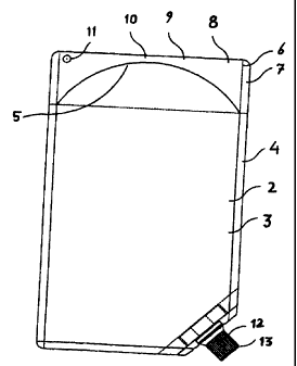
Fig. 2 shows a reservoir 100 in suspended form, whereby
reservoir 100 is suspended on suspension 11, such that opening 12
forms the lowest point. For reasons of the drawing, the lowest
point of the reservoir can be arranged not down on the side but
rather in the right, lower corner.
CA 02309840 2000-05-11
21
It can also be seen that protective film 14 has already been
removed. Closure 13 is still in opening 12, however.
CA 02309840 2000-05-11
22
WO 99/25308 PCT/EP98/07292
List of Reference Symbols:
100 Reservoir
2 Front wall
3 Rear wall
4 Welding seam of the reservoir walls
Bottom of the reservoir
6 Standing element
7 Welding seam of the standing element
8 Front standing element
9 Rear standing element
Line
11 Suspension
12 opening
13 Closure
14 Protective film
Predetermined point of break
16 Valve