Language selection

Search

Patent 2309851 Summary

Third-party information liability

Some of the information on this Web page has been provided by external sources. The Government of Canada is not responsible for the accuracy, reliability or currency of the information supplied by external sources. Users wishing to rely upon this information should consult directly with the source of the information. Content provided by external sources is not subject to official languages, privacy and accessibility requirements.

Claims and Abstract availability

Any discrepancies in the text and image of the Claims and Abstract are due to differing posting times. Text of the Claims and Abstract are posted:

  • At the time the application is open to public inspection;
  • At the time of issue of the patent (grant).
(12) Patent Application: (11) CA 2309851
(54) English Title: TWO SIDED PILOTED WELD NUT
(54) French Title: ECROU A SOUDER A GUIDE AUX DEUX EXTREMITES
Status: Dead
Bibliographic Data
Abstracts

English Abstract


A two sided piloted weld nut enables the nut to be welded either way. It can
be used with a nut feeder, or to increase production on a manual welding
process.
These nuts will eliminate the root cause of common nuts being welded upside
down.


Claims

Note: Claims are shown in the official language in which they were submitted.


-4-
" The embodiments of the invention in which an exclusive property or
privilege is claimed are defined as follows."
1. A weld nut or the like including all shapes and projection patterns having
a
metal body with said projections extending outwardly from two faces. Having
pilot
members also extending outwardly on both faces, being of greater distance from
the
body than the said projections.
2. A weld nut or the like as stated in claim 1, having pilot portions with a
flat
surface of enough area to make contact with an electrode ensuring a good
current
flow. Two surfaces of the pilots to be parallel and concentric of the same
width,
diameter and height on both sides of the nut. Weld projections are to 6e
mirrored
and duplicated on both sides of the nut in pattern, width, length and height.
3. A weld nut or the like as stated in claim 1 and 2 in which the body, pilot
and
projections are made from the same metallic material.

Description

Note: Descriptions are shown in the official language in which they were submitted.


CA 02309851 2000-OS-26
-2-
1. "This invention relates to piloted weld nuts or the like, intended to be
positioned on a metal plate or sheet and welded to enable a member to be
fastened."
2. "It is common for all piloted weld nuts to have one flat surface that
contacts
with an electrode and the opposing side to have a locating pilot and
projections that
will enable the nut to be welded to a metal sheet. When the electrode contacts
the
flat surface an electric current is sent through the nut to the point of
greatest
resistance which is the opposing end contacting with the metal sheet. With the
pilot
located in the hole in the sheet, the weld projections contacting the surface
will bind
to the metal. This will fasten the nut to the sheet. This type of nut can be
inefficient
when it comes to fast production welding. Often nuts will be welded upside
down,
binding only until the part cools. This is a common problem in the Automotive
industry, usually caused from operator error or nut feeders that fail to
detect this.
Also the large flat surface of the nut that contacts with the electrode can
create
expulsion and loss of heat."
3. "I have found these disadvantages can be overcome by duplicating the pilot
and weld projections on both sides of the nut. With the pilot member being of
greater distance from the body than the weld projections the electrode will
now
make contact with the pilot. The smaller surface area of the pilot creates a
more
concentrated current flow and the weld projections on the opposing end will
bind to
the metal sheet, usually with a deeper weld penetration than an ordinary weld
nut.
The advantage of the two sided weld nut is the fact that it will eliminate the
root
cause of upside down nuts being welded, lowering the cost of rejected
material. With
the two sided piloted weld nuts you can increase production. Operators will
not
have to be cautious of which way they are placing the nut, also you can
automate by
use of a nut feeder with relative ease."
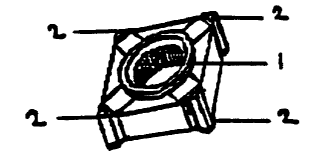
4. In the drawings which illustrate the embodiments of the invention. Figure 1
is a perspective view of a typical square weld nut with pilots and projections
extending both top and bottom of the nut. Figure 2 is a top view of this
embodiment.
Figures 3 and 4 are side views of this embodiment. Figure 5 is a perspective
view of
a typical hex shaped weld nut with pilot and weld projections on both top and
bottom. Figure 6 is the top view of this embodiment. Figure 7 is the side view
of this
embodiment. Figure 8 shows the weld nut example in Figures 5, 6, 7
demonstrating
the application and process as a sectional drawing including the electrode 4,
base 5
and the metal sheet 3 that the nut is welded to.
The weld nuts shown consists of two pilots l,on the top and bottom of the
nut. One end of the pilot 1, will locate in a hole in the metal sheet 3, on
the opposing
end the pilot 1 will contact with the electrode 4. When an electric current is
sent
through the electrode 4 and through the weld nut the resistance between the
weld
projections 2 and the metal sheet 3 create the weld.

Representative Drawing
A single figure which represents the drawing illustrating the invention.
Administrative Status

For a clearer understanding of the status of the application/patent presented on this page, the site Disclaimer , as well as the definitions for Patent , Administrative Status , Maintenance Fee  and Payment History  should be consulted.

Administrative Status

Title Date
Forecasted Issue Date Unavailable
(22) Filed 2000-05-26
(41) Open to Public Inspection 2001-11-26
Examination Requested 2002-08-15
Dead Application 2005-12-29

Abandonment History

Abandonment Date Reason Reinstatement Date
2004-12-29 R30(2) - Failure to Respond
2004-12-29 R29 - Failure to Respond
2005-05-26 FAILURE TO PAY APPLICATION MAINTENANCE FEE

Payment History

Fee Type Anniversary Year Due Date Amount Paid Paid Date
Application Fee $150.00 2000-05-26
Maintenance Fee - Application - New Act 2 2002-05-27 $100.00 2002-04-03
Request for Examination $200.00 2002-08-15
Maintenance Fee - Application - New Act 3 2003-05-26 $50.00 2003-03-25
Maintenance Fee - Application - New Act 4 2004-05-26 $50.00 2004-05-11
Owners on Record

Note: Records showing the ownership history in alphabetical order.

Current Owners on Record
CLARKE, LEE ERNEST
Past Owners on Record
None
Past Owners that do not appear in the "Owners on Record" listing will appear in other documentation within the application.
Documents

To view selected files, please enter reCAPTCHA code :


To view images, click a link in the Document Description column. To download the documents, select one or more checkboxes in the first column and then click the "Download Selected in PDF format (Zip Archive)" or the "Download Selected as Single PDF" button.

List of published and non-published patent-specific documents on the CPD .

If you have any difficulty accessing content, you can call the Client Service Centre at 1-866-997-1936 or send them an e-mail at CIPO Client Service Centre.


Document
Description 
Date
(yyyy-mm-dd) 
Number of pages   Size of Image (KB) 
Representative Drawing 2001-10-31 1 4
Drawings 2000-05-26 1 20
Abstract 2000-05-26 1 8
Description 2000-05-26 1 70
Claims 2000-05-26 1 24
Cover Page 2001-11-19 1 23
Correspondence 2000-07-07 1 1
Assignment 2000-05-26 3 65
Prosecution-Amendment 2002-08-15 1 19
Fees 2003-03-25 2 34
Fees 2002-04-03 2 93
Prosecution-Amendment 2004-06-29 5 152
Correspondence 2006-02-28 2 74
Fees 2004-05-11 1 66