Note: Descriptions are shown in the official language in which they were submitted.
CA 02309972 2000-05-15
WO 00/15735 PCT/US99/20325
TWO STAGE HYDROPROCESSING WITH VAPOR-LIOUID
I NTERSTAGE CONTACTING FOR VAPOR HETEROATOM
REMOVAL
Field of the Invention
The invention relates to hydroprocessing hydrocarbonaceous feeds using
two hydroprocessing reaction stages, with interstage vapor-liquid contacting
for
vapor impurity removal. More particularly the invention relates to
catalytically
hydroprocessing a hydrocarbonaceous feed in two consecutive reaction stages,
both of which produce a liquid and a vapor effluent. Impurities such as
heteroatom (e.g., sulfur) components, are removed from the first stage vapor
by
contacting it with hydroprocessed liquid, which is then passed into the second
stage for hydroprocessing and the impurity-reduced first stage vapor is
combined
with the second stage effluent, for product recovery.
Backgroand of the Invention
As supplies of lighter and cleaner feeds dwindle, the petroleum industry will
need to rely more heaviby on relativelv high boiling feeds derived from such
materials as coal. tar sands, shale oil, and heavy crudes. all of which
typically
contain significantly more undesirable components, especially from an
environmental point of view. These components include halides, metals.
unsaturates and heteroatoms such as sulfur, nitrogen, and oxygen. Furthermore,
due to environmental concerns, specifications for fuels, lubricants, and
chemical
products, with respect to such undesirable components, are continually
becoming
tighter. Consequently, such feeds and product streams require more upgrading
in
order to reduce the content of such undesirable components and this increases
the
cost of the finished products.
*rB
CA 02309972 2000-05-15
WO 00/15735 PCT/US99/20325
2
In a hydroprocessing process, at least a portion of the heteroatom
compounds are removed, the molecular structure of the feed is changed. or both
occur by reacting the feed with hydrogen in the presence of a suitable
hydroprocessing catalyst. Hydroprocessing includes hydrogenation.
hydrocracking. hydrotreating, hydroisomerization and hydrodewaxing, and
therefore plays an important role in upgrading petroleum streams to meet more
stringent quality requirements. For example, there is an increasing demand for
improved heteroatom removal, aromatic saturation and boiling point reduction.
In order to achieve these Qoals more economically, various process
configurations
have been developed, including the use of multiple hydroprocessing stages as
is
disclosed, for example. in U.S. patents 2,952,626: 4,021,330; 4,243,519 and
5,522,983.
SUMMARY OF THE INVENTION
The invention relates to catalytically hydroprocessing a
hydrocarbonaceous feed in two consecutive reaction stages. both of which
produce a liquid and a vapor effluent. Impurities. such as heteroatom (e.g.,
sulfur) compounds or other undesirable feed components. are removed from the
first stage vapor by contacting it with hydrocarbonaceous liquid. to transfer
the
impurities from the vapor into the liquid. After contacting. the vapor and
liquid
are separated. and the impurity-laden contacting liquid is passed into the
second
reaction stage, along with the first stage liquid effluent, for further
hydroprocessing. The second stage effluent comprises hydroprocessed vapor
and liquid which have an impurity level lower than that of the first stage
effluents. with the second stage liquid effluent comprising hydroprocessed
product liquid. The second stage and contacting stage vapor effluents. both of
which have an impurity level lower than that of the feed and first stage
effluents.
are cooled to condense at least some of the hydrocarbonaceous material in the
vapor to liquid. This liquid may be combined with the second stage liquid
effluent. as hydroprocessed product liquid. The contacting is achieved in a
CA 02309972 2000-05-15
WO 00/15735 PCT/US99/20325
3
countercurrent or crosscurrent flow contacting stage or zone in which the
vapor
flows up. The contacting zone comprises liquid-vapor contacting media. The
hydrocarbonaceous contacting liquid is preferably liquid effluent produced bv
the process of the invention. that has been at least partially hydroprocessed,
as is
explained in more detail below. The first reaction stage is preferably a
cocurrent
gas and liquid flow stage. while the second reaction stage can be either a
cocurrent or a countercurrent gas and liquid flow stage. [n one embodiment.
the
contacting and second stage vapor effluents are combined and cooled to
condense and recover the hydroprocessed hydrocarbonaceous material present in
the vapors. In another embodiment, the contacting stage vapor effluent is
combined with the second stage vapor and liquid effluents and the mixture sent
to a separator. to separate the vapor from the hydroprocessed liquid. The
separated vapors are then cooled to condense and separate the vaporized,
hydroprocessed hydrocarbonaceous material as liquid, which is then combined,
as additional product liquid, with the second stage liquid effluent. If
desired, the
impurity-reduced contacting stage vapor effluent may be processed separately
from the second staae liquid effluent. Single or multiple stage cooling and
liquid-vapor separation may be used. Using a liquid-vapor contacting stage or
zone for removal of impurities or other components from the vapor, is
significant in reducing the need for a third reaction stage. which would be a
large
vapor reaction stage. for removing the impurities from the first stage vapor
effluent.
The first stage liquid and vapor effluents are in equilibrium with each
other, with respect to the impurity level in each phase. Accordingly,
therefore,
by hydrocarbonaceous contacting liquid is meant a hydrocarbonaceous liquid
which has an impuritv level no greater, and preferably less. than that present
in
the first stage liquid effluent. If the impuritv level of the contacting
liquid is the
same as that in the first stage liquid effluent. then the liquid is cooled
prior to
contact with the first stage vapor. in order to transfer impurities from the
vapor
CA 02309972 2000-05-15
WO 00/15735 PCT/US99/20325
4
into the liquid. Preferably the impurity level in the contacting liquid is
less than
that in the first stage liquid effluent and, more preferably. is also cooled
to a
temperature below that of the first stage vapor, prior to the contacting. This
assures more efficient. and greater impurity transfer, from the vapor to the
liquid. Typically. the contacting liquid will comprise either or both the
first and
second reaction stage liquid effluents. In the reaction stages, the
hydrocarbonaceous feed is reacted with hydrogen in the presence of a suitable
hydroprocessing catalyst at reaction conditions sufficient to achieve the
desired
hydroprocessing. The hydrogen is hydrogen gas, which may or may not be
mixed or diluted with other gas and vapor components that do not adversely
effect the reaction. products or process. If the hydrogen gas contains other
such
components. it is often referred to as hydrogen treat gas. If fresh hydrogen
or
substantially pure hydrogen is available, it is preferred that it be used at
least in
the second reaction stage. At least a portion. and more typically most (e.g.,
> 50
wt. %) of the hydrocarbonaceous material being hydroprocessed in each stage is
liquid at the reaction conditions. The hydroprocessing results in a portion of
the
liquid in each stage being converted to vapor. In most cases the
hydrocarbonaceous material will comprise hydrocarbons.
In its broad sense. the invention comprises a hydroproc'essing process for
removing one or more impurities from a hydrocarbonaceous feed which
comprises the steps of:
(a) reacting said feed with hydrogen in a first hydroprocessing reaction
stage in the presence of a hydroprocessing catalyst to form a first stage
effluent
having a lower impuritv content than said feed. said effluent comprisinQ a
first
stage hydroprocessed hydrocarbonaceous liquid and a vapor which contains
hydroprocessed hydrocarbonaceous feed components. wherein both said liquid
and vapor effluents contain said impurities, with said impurities in
equilibrium
between said liquid and vapor effluents:
CA 02309972 2000-05-15
WO 00/15735 PCT/US99/20325
(b) separating said first stage liquid and vapor effluents:
(c) contacting said vapor effluent. in a contacting stage. with a
hydrocarbonaceous liquid. under conditions such that impurities in said vapor
transfer to said liquid, to form a contacting stage effluent comprising a
hydrocarbonaceoous liquid of increased impurity content and a vapor
comprising hydroprocessed hydrocarbonaceous feed components having an
impuritv content less than that of said first stage vapor effluent, and
(d) reacting said first and contacting stage liquid effluents with hydrogen
in a second hydroprocessing reaction stage, in the presence of a
hydroprocessing
catalyst, to form a second stage effluent comprising a hydroprocessed
hydrocarbonaceoous liquid and a vapor comprising hydroprocessed
hydrocarbonaceous feed components, wherein said liquid has an impurity
content lower than that in said feed and first stage liquid effluent.
The second stage liquid effluent, which may require stripping, comprises
hydroprocessed product liquid. If desired, with a cocurrent flow second
reaction
stage, combined liquid and vapor effluents may merely be passed to a
separation
zone, for separating the vapor and liquid phases without prior cooling. The
separated vapor phase. which may be either all or a portion of (i) the second
stage vapor or (ii) a combination of both the second and contacting stage
vapors.
is then cooled to condense a portion of the hydroprocessed vapors as liquid.
which is then separated and recovered as additional hydroprocessed liquid. A
specific example of this process is a hydrotreating process for removing
heteroatom impurities, such as sulfur. nitrogen and oxygenate compounds. from
feeds such as middle distillate fuel fractions. and heavier feeds. It being
understood, however. that the invention is not limited to a hydrotreating
process.
This is explained in detail below. Further. and as a practical matter, the
vapor
effluent from each reaction staae will contain unreacted hvdroaen.
CA 02309972 2000-05-15
WO 00/15735 PCT/US99/20325
6
BRIEF DESCRIPTION OF THE DRAWINGS
Figure I schematically illustrates a flow diagram of an embodiment of the
invention using cocurrent flow reaction stages. with the contacting staae in a
separate vessel.
Figure 2 is a simple schematic flow diagram of an embodiment of the
invention with a cocurrent first reaction stage, a countercurrent second
reaction
stage, and with the contacting stage located in the second reaction stage
vessel.
DETAILED DESCRIPTION
By hydroprocessing is meant a process in which hydrogen reacts with a
hydrocarbonaceous feed to remove one or more impurities, to change or convert
the molecular structure of at least a portion of the feed, or both. An
illustrative,
but non-limiting example of impurities may include (i) heteroatom impurities
such as sulfur, nitrogen, and oxygen, (ii) ring compounds such as naphthenes,
aromatics, condensed aromatics and other cyclic unsaturates, (iii) metals,
(iv)
other unsaturates. (v) waxy materials and the like. Thus. by impurity is meant
any feed component which it is desired to remove from the feed by the
hvdroprocessing. Illustrative. but non-limiting examples of hydroprocessing
processes which can be practiced by the present invention include forming
lower
boiling fractions from light and heavv feeds bv hvdrocracking; hvdrogenating
aromatics and other unsaturates; hydroisomerization and/or catalvtic dewaxing
of waxes and waxy feeds, and demetallation of heavy streams. Ring-opening,
particularly of naphthenic rings, can also be considered a hydroprocessing
process. By hydrocarbonaceous feed is meant a primarily hydrocarbon material
obtained or derived from crude petroleum oil, from tar sands. from coal
liquefaction. shale oil and hydrocarbon synthesis. The reaction stages used in
the practice of the present invention are operated at suitable temperatures
and
pressures for the desired reaction. For example. typical hydroprocessinQ
temperatures will ranae from about 40 C to about 450 C at pressures from about
CA 02309972 2000-05-15
WO 00/15735 PCT/US99/20325
7
50 psig to about 3.000 psig, preferablv 50 to 2.500 psig. The tirst reaction
stage
vapor effluent may contain impurities or undesirable feed components. such as
sulfur or other heteroatom compounds, which it is desired to remove from the
first stage vapor. The hydrocarbonaceous contacting liquid will have an
impurity concentration no greater. and preferablv lower. than the impuritv
concentratioii in the first stage liquid effluent which is in equiiibrium with
the
first stage vapor. While this contacting liquid may be any hydrocarbonaceous
liquid which does not adversely affect either the process. or the desired
hydroprocessed product liquid. and into which the vapor impurities will
transfer.
it will more typically comprise either or both the first and second reaction
stage
liquid effluents. Preferably it will be cooled to a temperature lower than the
first
stage vapor effluent. prior to the contacting. While a lower impurity
concentration in the liquid will result in transfer of some impurities into it
from
the first stage vapor, having the contacting liquid at a temperature lower
than
that of the vapor, will result in transfer of more impurities. than if it was
at the
same temperature as the vapor.
Feeds suitable for use in such systems include those ranging from the
naphtha boiling range to heavy feeds, such as gas oils and resids. Non-
limiting
examples of such feeds which can be used in the practice of the present
invention include vacuum resid. atmospheric resid. vacuum Qas oil (VGO),
atmospheric gas oil (AGO), heavy atmospheric gas oil (HAGO). steam cracked
gas oil (SCGO). deasphalted oil (DAO), light cat cycle oil (LCCO). natural and
synthetic feeds derived from tar sands. shale oil. coal liquefaction.
hydrocarbons
svnthesized from a mixture of H, and CO via a Fischer-Tropsch type of
hydrocarbon synthesis. and mixtures thereof.
For purposes of hydroprocessing and in the context of the invention. the
terms "fresh hvdrogen*' and '`hvdrogen-containing treat Qas" are synonymous
and mav be either pure hydrogen or a hydrogen-containing treat aas which is a
CA 02309972 2000-05-15
WO 00/15735 PCT/US99/20325
8
treat gas stream containing hydrogen in an amount at least sufficient for the
intended reaction. plus other Qas or gasses (e.g., nitrogen and light
hydrocarbons
such as methane) which Nvill not adversely interfere with or affect either the
reactions or the products. These terms exclude recycled vapor effluent from
another stage which has not been processed to remove contaminants and at least
a portion of any hydrocarbonaceous vapors present. They are meant to include
either hydrogen or a hydrogen-containing gas from any convenient source,
including the hydrogen-containing gas comprising unreacted hydrogen
recovered from hydroprocessed vapor effluent, after first removing at least a
portion and preferably most of the hydrocarbons (e.g., Ca+-C5+) or
hvdrocarbonaceous material and anv contaminants (e.g.. H,S and NH3) from the
vapor, to produce a clean, hvdrogen rich treat gas. The treat gas stream
introduced into a reaction stage will preferably contain at least about 50
vol. %,
more preferably at least about 75 vol. % hydrogen. In operations in which
unreacted hydrogen in the vapor effluent of any particular stage is used for
hydroprocessing in any stage, there must be sufficient hydrogen present in the
fresh treat gas introduced into that stage for the vapor effluent of that
stage, to
contain sufficient hydrogen for the subsequent stage or stages.
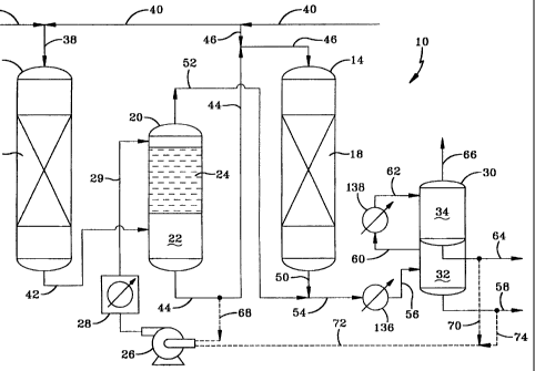
The invention can be further understood with reference to the Fi2ures.
Thus. referring first to Figure l, there is depicted a schematic flow diagram
of a
hydroprocessing unit useful in the practice of the invention. In this
particular
embodiment the hydroprocessing process is a hydrotreating process and the
reaction stages hvdrotreating stages. For the sake of simplicitv. not all
process
reaction vessel internals, valves, pumps. heat transfer devices etc. are
shown.
Thus, a hydrotreating unit 10 comprises first and second stage hvdrotreating
reaction vessels 12 and 14. containing respective fixed catalyst beds 16 and
18
within, for hvdrotreatinQ a distillate or diesel fuel feed. A third vessel 20.
which
is the liquid-vapor contacting stage vessel, contains a Qas-liquid disenaaging
and
separating zone 22 at the bottom and a bed of liquid-gas contacting material
24
CA 02309972 2009-01-12
9
in its upper portion. for the contacting stage. Also shown in this embodiment
is
a liquid transfer pump 26. an optional heat exchanger 28. a two stage
separator
vessel 30 with hot and cold separation zones 32 and 34. along with attendant
heat exchangers 136 and 138 for cooling. The heteroatom-containing hydrocarbon
feed to be hvdrotreated. enters the first stage reaction vessel 12 via lines
36 and
38. In this particular illustration of the invention. the feed is a petroleum
derived
distillate or diesel fuel fraction containing heteroatom compounds of sulfur.
nitrogen and perhaps oxvgen. Fresh. once-through hvdrogen or a treat gas
comprising hydrogen enters via lines 40 and 38. The feed and hydrogen pass
into vessel 12 and flow cocurrentlv down throuah the catalvst bed 16. which
contains a sulfur tolerant catalyst. in which the feed reacts with the
hydrogen in
the presence of the catalvst to remove oxygenates. sulfur and nitrogen
compounds present in the feed as H2S and NH3, water, and saturate oletins and
aromatics, to form a first stage effluent comprising a mixture of partially
hydroprocessed hydrocarbon liquid and vapor, with the vapor containing
vaporized feed components. unreacted hydrogen. H2S and NH;. As those skilled
in the art know. in hvdrotreating and other hvdroprocessing processes. the
amount of hvdrogen passed into a hvdroprocessing reaction stage is in excess
of
that amount theoreticallv required to achieve the desired degree of
conversion.
This is done to maintain a sufficient hydrogen partial pressure throughout the
reaction zone. Therefore. the vapor effluent from each hvdroprocessinQ
reaction
zone will contain the unreacted hydrogen. Most (e.g., ?-50 %) of the feed
hvdrotreating is accomplished in the first stage. In two stage hydrotreating
processes. it is not unusual for 60 %. 75 % and even _ 90 % of the heteroatom
(S, N and 0) compounds in the feed to be removed from the liquid in the first
stage, bv converting them to H~S NH3, and H~O. Therefore, the second stage
catalyst can be a more kineticallv active, but less sulfur tolerant catalyst
than the
first stage catalyst for heteroatom removal, and in addition can also achieve
greater aromatics saturation. In this embodiment the first staae cataivst may
comprise cobalt and molybdenum catalytic components supported on alumina.
CA 02309972 2000-05-15
WO 00/15735 PCT/US99/20325
I0
and the second stage catalyst may comprise nickel-molybdenum or nickel-
tungsten catalvtic metal components on an alumina support. The first stage
liquid and vapor effluents are in equilibrium with respect to the impurity
concentration in each phase and are removed from the bottom of vessel 12. and
passed via line 42, into gas-liquid disengaging and separating zone 22. in the
bottom of the contact stage vessel 20. The partially hydrotreated liquid
separates
from the vapor effluent, is removed from the bottom of the vessel and passed.
via lines 44 and 46. into the top of the second stage reaction vessel 14. In
this
embodiment, the first reaction stage is operated at a higher pressure than the
second reaction stage. Therefore a liquid transfer pump may not be required.
The disengaged and separated first stage vapor passes up through the liquid-
gas
contacting bed means 24, in which it meets with downtlowing hydrocarbon
liquid that has been at least partially hydrotreated, and in which the
concentration of the impurity compounds is no greater than, and preferably
less,
than that in the first stage liquid effluent in equilibrium with the first
stage vapor
effluent. Prior to contacting, the liquid is preferably cooled to a
temperature
lower than that of the first stage vapor in the contacting stage. The
contacting
means comprises any known liquid-vapor contacting means. such as rashig
rings, berl saddles. Nvire mesh. ribbon, open honevcomb. aas-Iiquid contacting
trays. such as bubble cap trays and other devices. etc. In the embodiment
shown
in the Figures. the dashed lines shown as the contacting means 24. represent
gas-
liquid contacting travs. Optional heat exchanger 28 cools the hydrocarbon
liquid, if needed. to a temperature lower than that of the vapor. The liquid
temperature is determined by the vapor temperature and the relative
concentrations, solubilities and condensation temperatures of the heteroatom
compounds in each phase. The combination of temperatures and concentrations
is such as to transfer the desired amount of these compounds to the liquid by
absorption, condensation and equiiibrium concentration differentials, to
achieve
the desired vapor purity. As is shown, in this embodiment the contacting
liquid
mav comprise second stage liquid effluent that mav or mav not be cooled prior
CA 02309972 2009-01-12
II
to contacting, bv heat exchanger 28. It may also comprise contacting stage
effluent that is recycled and cooled, by heat exchanger 28. to a temperature
below that of the tirst stage vapor effluent in the contacting stage. It may
also be
a mixture of these two liquids, with or without cooling. Further. and as shown
in
Figure 1. all or a portion of the condensed, hydrotreated liquid recovered
from
the contacting and second stage vapor effluents may be used as contacting
liquid, either with or without first, second and/or contacting stage liquid
effluent.
The contacting liquid, now containing more of these impurities than before it
contacted the first stage vapor effluent, passes down into the separating and
disengaging zone 22. in which it mixes with the first stage liquid effluent,
with
which it is passed into the second reaction stage. At the same time, fresh
hydrogen or a hydrogen treat gas is passed into the top of the second stage
via
lines 40, 48 and 46. In the second reaction stage, the hydrocarbon liquid and
hydrogen both pass cocurrently down through catalyst bed 18. During the
second stage reaction, most of the remaining feed heteratom compounds, which
are now sulfur and nitrogen compounds, are removed from the liquid, with the
sulfur and nitrogen forming H2S and NH;. The H2S and NH3 pass into the
second stage vapor. Both the contacting and second stage vapor effluents
contain C4_-C;_ hvdrocarbon vapors and normally gaseous C.,_-C;_ hydrocarbons.
The heteroatom reduced hvdrocarbon (iquid and heteroatom containing vapor
both pass down through to the bottom of vessel 18, from which they are
removed tosether. via line 50. and combine with the heteroatom reduced first
reaction stage vapor removed from vessel 20, via line 52. The combined liquid
and vapor effluent is then passed into heat exchanger 136, via line 54, and
cooled
to condense most of the heavier hydrocarbon components in the vapor. with the
resulting vapor and liquid mixture then passed into the first. or hot
separating
zone 32 in vessel 30. via line 56. In zone 32, the vapor is disengaged and
separated from the liquid. with the hydrotreated liquid removed via line 58
and
sent to a product stripper. The vapor is removed from zone 32 via line 60 and
passed through a second, or cold heat exchanger 138, in which it is further
cooled
CA 02309972 2000-05-15
WO 00/15735 PCT/US99/20325
12
down to condense out, as liquid. more hydrotreated hydrocarbons (e.a.. C.,+-
CS_).
The remaining vapor comprises mostlv methane and hvdrogen. along with most
of the H2S and NH3. The condensed hydrocarbons and vapor containing H'S
and NH3 are passed. via line 62 into cold separating zone 34 to separate them.
with the liquid removed via line 64 and sent to the product striper. The
remaining vapor is removed as tail gas via line 66, and sent to further
processing
for removal of the H2S and NH3. Since either or both the first stage and
second
stage liquid effluent may be used as the contacting liquid for the contacting
stage, the recycle lines for these streams are shown as dotted lines. Thus,
line 68
is a tie-in point for recycling a slip stream of the liquid recovered from the
bottom of vessel 20 and passed. via liquid pump 26, through heat exchanger 28,
which cools it to a temperature sufficiently below that of the first stage
vapor
effluent, for the impurities to transfer from the vapor, into the contacting
liquid.
This cooled liquid is then passed, via line 29, back up into the top of vessel
20.
Lines 70, 72 and 74 are shown as optional transfer and recycle lines, for
passing
hydrotreated, second stage liquid effluent and/or hydrotreated liquid
recovered
from the second and/or contacting stage vapors, back into pump 26, optional
heat exchanger 28. line 29 and into the top of 20 as all or part of the
contacting
liquid.
Figure 2 schematicallv illustrates another embodiment of the process of
the invention, in which both the liquid-vapor contacting stage and second
hydrotreating reaction stages are located in the same vessel, with the first
and
second reaction stages being cocurrent gas and liquid flow and countercurrent
gas and liquid flow stages, respectivelv. As is the case for the embodiment
shown in Figure 1. this embodiment will also be explained with particular
reference to hvdrotreating a heteroatom-containing fuel distillate fraction.
Accordingly, the same vessels, heat exchangers, lines and pump shown in
Figures 1 and which have the same function, have the same numbers in both
Figures 1 and 2. There are also substantial differences in the embodiment
shown
CA 02309972 2000-05-15
WO 00/15735 PCTIUS99/20325
13
in Figure 2. in that the first stage liquid effluent is not used as all or a
part of the
contacting liquid and. further. the combined first and second stage vapors are
contacted with the liquid. in the contacting stage. Otherwise the process is
similar to the embodiment shown in Figure 1.
Referring to Figure 2. in the hydrotreating unit 100, the feed is passed via
lines 36 and 38 into the top of first reaction stage vessel 12. At the sanie
time.
fresh hydrogen or hvdroaen-containing treat gas is passed into the vessel via
lines 40 and 38. The feed and hydrogen pass cocurrently down through the
catalyst bed 16. in which heteroatom compounds are removed and some
components are saturated. as in the embodiment of Figure 1. The heteroatom
compounds are removed primarily by conversion to H2S, NH3 and water. This
produces a first stage effluent comprising a partially hydrotreated liquid and
vapor, wherein the vapor comprises partially hydrotreated and vaporized feed
components, hydrogen, H,S. NH3 and lighter hydrocarbons (mostly methane).
The liquid and vapor effluents pass down into the bottom of the vessel from
which they are removed. via line 42, and passed into feed inlet and vapor
space
82 in vessel 80. Vessel 80 contains both the liquid-vapor contacting means 24
for the contacting stage and a hydrotreating catalyst bed 18 below, for the
second
stage hydrotreating. The first stage liquid effluent passes down, and the
hydrogen and vapor effluent pass up, through the second hydrotreating reaction
stage. defined primarily by hydrotreating catalyst bed 18. Thus. the liquid
and
hydrogen flow countercurrently to each other in the second reaction stage. The
second stage hydrotreated vapor effluent flows up from bed 18 and into
contacting stage zone 24. in which it combines with the first stage vapor
effluent. The combined first and second stage vapor effluents flow up through
bed 24. in which they contact downflowing, hydrotreated. second stage liquid
which enters above the bed. via line 29. As in the embodiment in Figure 1.
heteroatom compounds remaining in the combined vapors are removed by
absorption. condensation and/or equilibrium differential transfer. to the
CA 02309972 2000-05-15
WO 00/15735 PCT/US99/20325
14
downflowing liquid. The contacting stage vapor effluent. which now contains
H7S, NH3 and substantially reduced in heteroatom feed components. is then
passed into line 86. where it combines with the hydrotreated second stage
liquid
effluent from line 84. The contacting stage liquid effluent flows down 24 and
into catalyst bed 18. in which it mixes with the downflowing first stage
liquid
effluent. Hydrogen or a hydrogen treat gas is passed up into the second stage
hydrotreating zone via line 85 and reacts with the feed heteroatom compounds
in
the downflowing liquid, thereby removing them from the liquid by converting
them primarily to H2S and NH3. The hydrotreated second stage liquid effluent
is
removed via line 84. combines with the contacting stage vapor effluent, and
the
mixture is passed. via line 54, through a hot heat exchanger. etc., as is the
case
for the embodiment shown in Figure 1. Hydrotreated contacting liquid may be
derived from one or more of (i) the second stage liquid effluent and (ii)
hydrotreated hydrocarbon vapor components that have been condensed to liquid
and recovered. This is shown by the optional tie lines 70. 74, 72 and 68. As
is
the case for the embodiment shown in Figure 1, the hydrotreated liquids in
lines
58 and 64 will typically be sent to a stripper and the contacting liquid may
also
be derived from the stripped liquid.
Those skilled in the art will appreciate that the invention can be extended
to more than two reaction and one contacting stages. Thus. one mav also
employ three or more reaction stages in which the partially processed liquid
effluent from the first stage is the second stage feed, the second stage
liquid
effluent is the third stage feed, and so on, with attendant vapor stage
contacting
in one or more liquid-vapor contacting stages. By reaction stage is meant at
least one catalytic reaction zone in which the liquid, or mixture of liquid
and
vapor reacts with hydrogen in the presence of a suitable hydroprocessing
catalyst
to produce an at least partially hydroprocessed effluent. The catalyst in a
reaction zone can be in the form of a fixed bed. a fluidized bed or dispersed
in a
slurry liquid. More than one catalyst can also be employed in a particular
zone
CA 02309972 2004-03-09
as a mixture or in the form of layers (for a fixed bed). Further. where tixed
beds
are employed, more than one bed of the same or different catalyst may be used.
so that there will be more than one reaction zone. The beds may be spaced
apart
with optional 2as and liquid distribution means upstream of each bed, or one
bed
of two or more separate catalysts may be used in which each catalyst is in the
form of a laver. -ith little or no spacing between the layers. The liquid
will pass
successively from one zone to the next.
The term "hvdrotreating" as used herein refers to processes wherein a
hydrogen-containing treat gas is used in the presence of a suitable catalyst
which
is primarily active for the removal of heteroatoms. such as sulfur. and
nitrogen.
non-aromatics saturation and. optionally, saturation of aromatics. Suitable
hydrotreating catalysts for use in a hydrotreating embodiment of the invention
include any conventional hydrotreating catalyst. Examples include catalysts
comprising of at least one Group VIII metal catalytic component. preferably
Fe,
Co and Ni, more preferably Co and/or Ni, and most preferably Co: and at least
one Group VI metal catalytic component, preferably Mo and W. more preferably
Mo, on a high surface area support material, such as alumina. Other suitable
hvdrotreatinL7 catalvsts include zeolitic catalvsts, as well as noble metal
catalvsts
where the noble metal is selected from Pd and Pt. The Groups referred to
herein
are those found in the Periodic Table of the Elements, copyrighted in 1968 by
the Sargent-Welch Scientific Company. As mentioned above. it is within the
scope of the present invention that more than one type of hydrotreating
catalyst
may be used in the same reaction stage or zone. Typical hvdrotreating
temperatures range from about I00 C to about 400 C with pressures t'rom about
50 psig to about 3.000 psig, preferablv from about 50 psig to about 2.500
psig.
If one of the reaction stages is a hydrocracking stage. the catalyst can be
any
suitable conventional hvdrocracking cataivst run at tvpical hvdrocracking
conditions. Typical hvdrocracking catalysts are described in US Patent No.
4.921.595 to UOP. Such catalvsts are
CA 02309972 2000-05-15
WO 00/15735 PCT/US99/20325
16
typically comprised of a Group VIII metal hydrogenating component on a
zeolite cracking base. Hydrocracking conditions include temperatures from
about 200 to 425 C: a pressure of about 200 psig to about 3.000 psig; and
liquid
hourly space velocity from about 0.5 to 10 V/V/Hr, preferably from about I to
5
V/V/Hr. Non-limiting examples of aromatic hydrogenation catalysts include
nickel, cobalt-molvbdenum. nickel-molvbdenum. and nickel-tungsten. Noble
metal (e.g., platinum and/or palladium) containing catalysts can also be used.
The aromatic saturation zone is preferably operated at a temperature from
about
40 C to about 400 C, more preferably from about 260 C to about 350 C. at a
pressure from about 100 psig to about 3,000 psig, preferably from about 200
psig to about 1,200 psig, and at a liquid hourly space velocity (LHSV) of from
about 0.3 V!V/Hr. to about 2 V/V/Hr.
It is understood that various other embodiments and modifications in the
practice of the
invention will be apparent to, and can be readily made by, those skilled in
the art
without departing from the scope and spirit of the invention described above.
Accordingly, it is not intended that the scope of the claims appended hereto
be
limited to the exact description set forth above, but rather that the claims
be
construed as encompassing all of the features of patentable novelty which
reside
in the present invention. including all the features and embodiments which
would be treated as equivalents thereof by those skilled in the art to which
the
invention pertains.