Note: Descriptions are shown in the official language in which they were submitted.
CA 02310033 2000-OS-15
WO 99/25291 PCTlUS98124298
1
ABSORBENT ARTICLE HAVING IMPROVED
FECAL STORAGE STRUCTURE
This application claims the benefit of U.S. Provisional Application
No. 60/066,777, filed November 14, 1997.
FIELD OF TAE INVENTION
The present invention relates to articles which absorb and/or contain bodily
exudates, including disposable absorbent articles such as diapers, adult
incontinence
products, sanitary napkins and the like. More particularly, the invention
relates to
disposable absorbent articles having improved fecal material management
properties.
BACKGROUND OF TftE INVENTION
- The major function of absorbent articles such as diapers and adult
incontinence briefs is to prevent body exudates from soiling, wetting, or
otherwise
contaminating clothing or other articles, such as bedding, that come in
contact with
the wearer. In recent years, disposable diapers, such as those disclosed in U.
S. Pat.
No. 3,860,003 issued to Kenneth Barclay Buell on Jan. 14, 1975, have become
very
popular with the public and have generally replaced durable cloth absorbent
articles
because of their convenience and reliability. However, despite the
effectiveness of
such disposable absorbent articles, body exudates often still leak or are
stored in the
diaper such that the exudates soil and/or irritate the skin of the wearer.
CA 02310033 2000-OS-15
WO 99/25291 PCT/US98/24298
2
The undesirable effects of leakage and/or improper containment are especially
evident with regard to fecal matter deposited in the diaper. Feces contained
in the
diaper can harm the skin of the wearer over time and feces leaking from the
diaper
almost invariably presents unpleasant, messy clean-ups. Thus, several attempts
have
been made to add features to diapers such as barriers, pockets, spacers,
transverse
barriers, apertured topsheets and the like to limit the movement of the
material across
the topsheet and/or to better confine fecal matter in the diaper. However,
such
attempts have been generally unsuccessful due to their cost and complexity or
due to
their limited success in reducing the negative effects of the feces.
Although the present invention may be adapted to provide improved
management of any bodily exudates, the embodiments described hereinbelow are
especially suitable for controlling viscous fluid bodily wastes. Such viscous
fluid
bodily wastes include soft or runny feces, and the like, which are generally
more
viscous than urine but less viscous than normal solid adult feces. Viscous
fluid bodily
wastes are difficult to absorb and/or contain in conventional absorbent
structures
because the normal capillary forces which acquire and transport extremely low
viscosity fluids like urine are insufficient to move such viscous fluid bodily
wastes.
Thus, the viscous fluid body wastes often remain on the topsheet of the
article where
they are generally unrestricted in movement and accessible to and in contact
with the
wearer's skin. Further, the fluid characteristics of the waste permit .it to
flow across
the topsheet and sometimes leak out of the article. Accordingly, the special
characteristics of viscous fluid bodily wastes need to be addressed by unique
storage
structures.
Accordingly, it would be desirable to provide an absorbent structure with
improved feces management properties. Further, it would be advantageous to
provide an economical disposable absorbent article with the ability to
minimize the
negative effects of feces or other viscous fluid bodily waste on the wearer or
the
caregiver. It would also be advantageous to provide an absorbent article which
is
specifically designed to accept viscous fluid bodily wastes such as fecal
material,
CA 02310033 2000-OS-15
WO 99/25291 PC'T/US98/24298
3
especially relatively lower viscosity fecal material such as soft or runny
feces. Also, it
would be desirable to provide an absorbent article having suffcient effective
capacity
and retention capability to store feces deposited therein safely and cleanly
away from
the wearer's skin and/or clothing throughout the expected time of use.
SUMMARY OF TAE INVENT10N
In order to better manage viscous fluid bodily wastes, the present invention
provides an absorbent article having a first waist region, a second waist
region
opposed to the first waist region and a crotch region disposed between the
first waist
region and the second waist region. The absorbent article preferably comprises
a
liquid pervious topsheet, a liquid pervious backsheet joined to at least a
portion of the
topsheet, an absorbent core disposed between at least a portion of the
topsheet and
the backsheet, and a waste management element disposed in at least a portion
of the
crotch region. The waste management element preferably includes an acceptance
element having an effective open area of at least about 30% and a storage
element
disposed between at least a portion of the acceptance element and the
backsheet.
The storage element preferably has a compressive resistance of at least about
70%..
The effective open area ensures that viscous fluid bodily wastes are quickly
and
efficiently imbibed by the article. Further, the improved compressive
resistance may
reduce the likelihood that normal wearing forces will release the waste from
the
storage element once the waste is imbibed by the article. Accordingly, the
absorbent
article of the present invention may reduce the likelihood of harm to the
wearer's skin
and/or the inconvenience to the caregiver normally associated with bowel
movements, and especially runny feces.
BRIEF DESCRTPT10N OF THE DRAWINGS
While the specification concludes with claims particularly pointing out and
distinctly claiming the subject matter which is regarded as the present
invention, it is
believed that the description will be better understood from the following
descriptions
which are taken in conjunction with the accompanying drawings in which like
designations are used to designate substantially identical elements.
CA 02310033 2000-OS-15
WO 99r15291
4
PCT/IJS98/24298
Figure I is a plan view of an absorbent article embodiment of the present
invention having portions cut away to reveal the underlying structure, the
body-
facing surface of the diaper facing the viewer.
Figure 2 is a schematic front view of an apparatus which may be used to
measure Acceptance Under Pressure and Storage Under Pressure characteristics
of
structures.
Figure 3 is a schematic side view of an apparatus which may be used to
measure retention and Immobilization Under Compressed Inversion
characteristics of
structures.
Figure 4 is a plan view of a piece of the apparatus shown in Figure 3.
Figure 5 is a plan view of one embodiment of the present invention having
portions cut away to reveal the underlying structure, the body facing surface
of the
diaper facing the viewer.
Figure fi is a cross sectional view of the diaper of Figure 5 taken through 6-
6.
Figure 6A is a cross sectional view of an alternative embodiment of the
present invention.
Figure 7 is a plan view of one embodiment of the present invention having
portions cut away to reveal the underlying structure, the body facing surface
of the
diaper facing the viewer.
Figure 8 is a plan view of an alternative embodiment of the present invention.
CA 02310033 2000-OS-15
WO 99!25291 PCT/IJS98/24298
Figure 9 is a 3-dimensional graphical representation of the relationship
between Acceptance Under Pressure, Storage Under Pressure and Immobilization
Under Compressed Inversion values of exemplary structures.
Figure 10 is a 3-dimensional graphical representation of the relationship
between Acceptance Under Pressure, Storage Under Pressure and retention values
of
exemplary structures.
Figure 11 is a 2-dimensional graphical representation of the relationship
between Acceptance Under Pressure and Storage Under Pressure values of
exemplary structures.
Figure 12 is a 2-dimensional graphical representation of the relationship
between retention and Immobilization Under Compressed Inversion values of
exemplary structures.
Figure 13 is a 2-dimensional graphical representation of the relationship
between Immobilization Under Compressed Inversion and Storage Under Pressure
values of exemplary structures.
Figure 14 is a 2-dimensional graphical representation of the relationship
between Storage Under Pressure and Receptivity Under Pressure values of
exemplary
structures.
Figure 15 is a 2-dimensional graphical representation of the relationship
between Storage Under Pressure and Compressive Resistance values of exemplary
structures.
Figure 16 is a 2-dimensional graphical representation of the relationship
between Immobilization Under Compressed Inversion and Compressive Resistance
values of exemplary structures.
CA 02310033 2000-OS-15
WO 99/25291 PCT/US98124298
6
Figure 17 is a 2-dimensional graphical representation of the relationship
between Storage Under Pressure and Void Volume values of exemplary structures.
Figure 18 is a 2-dimensional graphical representation of the relationship
between Immobilization Under Compressed Inversion and Compressive Resistance
values of exemplary structures.
Figure 19 is a 2-dimensional graphical representation of the relationship
between Immobilization Under Compressed Inversion values of exemplary
structures
and the Effective Open Area of an associated acceptance element.
Figure 20 is a 2-dimensional graphical representation of the relationship
between Storage Under Pressure values of exemplary structures and the
Effective
Open Area of an associated acceptance element.
' Figure 21 is a 2-dimensional graphical representation of the relationship
between Acceptance Under Pressure values of exemplary structures and the
Effective
Open Area of an associated acceptance element.
Figure 22 is a 2-dimensional graphical representation of the relationship
between Storage Under Pressure values of exemplary structures and the
Effective
Open Area of an associated acceptance element.
DETATLED DESCRTPT10N OF TAE INVENTION
As used herein, the term "absorbent article" refers to devices which absorb
and contain body exudates, and more specifically, refers to devices which are
placed
against or in proximity to the body of the wearer to absorb and contain the
various
exudates discharged from the body. The term "disposable" is used herein to
describe
absorbent articles which generally are not intended to be laundered or
otherwise
restored or reused as an absorbent article (i.e., they are intended to be
discarded after
CA 02310033 2000-OS-15
WO 99/25291 PCT/US98/24298
7
a single use and, preferably, to be recycled, composted or otherwise disposed
of in an
environmentally compatible manner). (As used herein, the term "disposed" is
used to
mean that an elements) of the diaper is formed (joined and positioned) in a
particular
place or position as a unitary structure with other elements of the diaper or
as a
separate element joined to another element of the diaper. As used herein, the
term
"joined" encompasses configurations whereby an element is directly secured to
another element by affixing the element directly to the other element, and
configurations whereby an element is indirectly secured to another element by
affixing the element to intermediate members) which in turn are affixed to the
other
element.) A "unitary" absorbent article refers to absorbent articles which are
formed
of separate parts united together to form a coordinated entity so that they do
not
require separate manipulative parts like a separate holder and liner. A
preferred
embodiment of an absorbent article of the present invention is the unitary
disposable
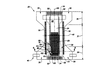
absorbent article, diaper 20, shown in Figure 1. As used herein, the term
"diaper"
refers to an absorbent article generally wom by infants and incontinent
persons about
the lower torso. The present invention is also applicable to other absorbent
articles
such as incontinence briefs, incontinence undergarments, absorbent inserts,
diaper
holders and liners, feminine hygiene garments, wipes, mops, bandages and the
Iike.
Figure 1 is a plan view of the diaper 20 of the present invention in a flat-
out,
state with portions of the structure being cut-away to more clearly show the
construction of the diaper 20. The portion of the diaper 20 which faces the
wearer is
oriented towards the viewer. As shown in Figure l, the diaper 20 preferably
comprises a liquid pervious topsheet 24; a liquid impervious backsheet 26; an
absorbent core 28, which is preferably positioned between at least a portion
of the
topsheet 24 and the backsheet 26; side panels 30; elasticized leg cuffs 32; an
elastic
waist feature 34; and a fastening system generally designated 40. Diaper 20 is
shown
in Figure 1 to have a first waist region 36, a second waist region 38 opposed
to the
first waist region 36 and a crotch region 37 located between the first waist
region and
the second waist region. The periphery of the diaper 20 is defined by the
outer edges
of the diaper 20 in which the longitudinal edges 50 run generally parallel to
the
CA 02310033 2000-05-15
WO 99125291
PCTNS98I24298
8
longitudinal centerline 100 of the diaper 20 and the end edges 52 run between
the
longitudinal edges 50 generally parallel to the lateral centerline 110 of the
diaper 20.
The chassis 22 of the diaper 20 comprises the main body of the diaper 20.
The chassis 22 comprises at least a portion of the absorbent core 28 and
preferably an
outer covering layer including the topsheet 24 and the backsheet 26. If the
absorbent
article comprises a separate holder and a liner, the chassis 22 generally
comprises the
holder and the liner. (For example, the holder may comprise one or more layers
of
material to form the outer cover of the article and the liner may comprise an
absorbent assembly including a topsheet, a backsheet, and an absorbent core.
In such
cases, the holder and/or the liner may include a fastening element which is
used to
hold the liner in place throughout the time of use.) For unitary absorbent
articles, the
chassis 22 comprises the main structure of the diaper with other features
added to
form the composite diaper structure. While the topsheet 24, the backsheet 26,
and
the absorbent core 26 may be assembled in a variety of well known
configurations,
preferred diaper configurations are described generally in U.S. Pat. No.
3,860,003
entitled "Contractible Side Portions for Disposable Diaper" which issued to
Kenneth
B. Buell on January 14, 1975; U.S. Pat. No. 5,151,092 issued to Buell on
September
9, 1992; and U.S. Pat. No. 5,221,274 issued to Buell on June 22, 1993; and
U.S. Pat.
No. 5,554,145 entitled "Absorbent Article With Multiple Zone Structural
Elastic-
Like Film Web Extensible Waist Feature" which issued to Roe et a1. om
September
10, 1996; U.S. Pat. No. 5,569,234 entitled "Disposable Pull-On Pant" which
issued
to Buell et al. on October 29, 1996; U.S. Pat. No. 5,580,411 entitled "Zero
Scrap
Method For Manufacturing Side Panels For Absorbent Articles" which issued to
Nease et al. on December 3, 1996; and U.S. Patent Application Serial No.
08/915,471 entitled "Absorbent Article With Multi-Directional Extensible Side
Panels" filed August 20, 1997 in the name of Robles et al.; each of which is
incorporated herein by reference.
The backsheet 26 is generally that portion of the diaper 20 positioned
adjacent the garment facing surface 45 of the absorbent core 28 which prevents
the
CA 02310033 2000-OS-15
WO 99125291 PCTNS98124298
9
exudates absorbed and contained therein from soiling articles which may
contact the
diaper 20, such as bedsheets and undergarments. In preferred embodiments, the
backsheet 26 is impervious to liquids (e.g., urine) and comprises a thin
plastic film
such as a thermoplastic film having a thickness of about 0.012 mm (0.5 mil) to
about
0.051 mm (2.0 mils). Suitable backsheet films include those manufactured by
Tredegar Industries Inc. of Terre Haute, IN and sold under the trade names
X15306,
X10962 and X10964. Other suitable backsheet materials may include breathable
materials which permit vapors to escape from the diaper 20 while still
preventing
exudates from passing through the backsheet 26. Exemplary breathable materials
may include materials such as woven webs, nonwoven webs, composite materials
such as film-coated nonwoven webs, and microporous films such as manufactured
by
Mitsui Toatsu Co., of Japan under the designation ESPOIR NO and by EXXON
Chemical Co., of Bay City, TX, under the designation EXXAIRE. Suitable
breathable composite materials comprising polymer blends are available from
Clopay
Corporation, Cincinnati, OH under the name HYTREL blend P18-3097. Such
breathable composite materials are described in greater detail in PCT
Application No.
WO 95/16746, published on June 22, 1995 in the name of E. I. DuPont and
copending U.S. Patent Application Serial No. 08/744,487, filed on November 6,
1996 in the name of Curro. Other breathable backsheets including nonwoven webs
and apertured formed films are described in U.S. Pat. No. 5,571,096 issued to
Dobrin
et al. on November 5, 1996. Each of these references is hereby incorporated by
reference herein.
The backsheet 26, or any portion thereof, may be elastically extensible in one
or more directions. In one embodiment, the backsheet 26 may comprise a
structural
elastic-like film ("SELF") web. A structural elastic-like film web is an
extensible
material that exhibits an elastic-like behavior in the direction of elongation
without
the use of added elastic materials. The SELF web includes a strainable network
having at least two contiguous, distinct, and dissimilar regions. Preferably,
of the
regions is configured so that it will exhibit resistive forces in response to
an applied
axial elongation in a direction parallel to the predetermined axis before a
substantial
CA 02310033 2000-OS-15
WO 99/25291
PCT/US98/24298
portion of the other region develops significant resistive forces to the
applied
elongation. At (east one of the regions has a surface-pathlength which is
greater than
that of the other region as measured substantially parallel to the
predetermined axis
while the material is in an untensioned condition. The region exhibiting the
longer
surface-pathlength includes one or more deformations which extend beyond the
plane
of the other region. The SELF web exhibits at least two significantly
different stages
of controlled resistive force to elongation along at least one predetermined
axis when
subjected to an applied elongation in a direction parallel to the
predetermined axis.
The SELF web exhibits first resistive forces to the applied elongation until
the
elongation of the web is sufficient to cause a substantial portion of the
region having
the longer surface-pathlength to enter the plane of applied elongation,
whereupon the
SELF web exhibits second resistive forces to further elongation. The total
resistive
forces to elongation are higher than the first resistive forces to elongation
provided
by the first region. SELF webs suitable for the present invention are more
completely
described in U.S. Patent No. 5,518,801 entitled Web Materials Exhibiting
Elastic-
Like Behavior, which issued to Chappell, et, al. on May 21, 1996, which is
incorporated herein by reference. In alternate embodiments, the backsheet 26
may
comprise elastomeric films, foams, strands, or combinations of these or other
suitable
materials with nonwovens or synthetic films.
The backsheet 26 may be joined to the topsheet 24, the absorbent core 28 or
any other element of the diaper 20 by any attachment means known in the art.
For
example, the attachment means may include a uniform continuous layer of
adhesive, a
patterned layer of adhesive, or an array of separate lines, spirals, or spots
of adhesive.
One preferred attachment means comprises an open pattern network of filaments
of
adhesive as disclosed in U.S. Patent 4,573,986 entitled "Disposable Waste-
Containment Garment", which issued to Minetola et al. on March 4, 1986. Other
suitable attachment means include several lines of adhesive filaments which
are
swirled into a spiral pattern, as is illustrated by the apparatus and methods
shown in
U.S. Patent 3,911,173 issued to Sprague, Jr. on October 7, 1975; U.S. Patent
4,785,996 issued to Ziecker, et al. on November 22, 1978; and U.S. Patent
CA 02310033 2000-OS-15
WO 99/25291 PCTIUS98/24298
11
4,842,666 issued to Werenicz on June 27, 1989. Each of these patents are
incorporated herein by reference. Adhesives which have been found to be
satisfactory are manufactured by H. B. Fuller Company of St. Paul, Minnesota
and
marketed as HL-1620 and HL-1358-XZP. Alternatively, the attachment means may
comprise heat bonds, pressure bonds, ultrasonic bonds, dynamic mechanical
bonds,
or any other suitable attachment means or combinations of these attachment
means as
are known in the art.
The topsheet 24 is preferably positioned adjacent the body surface 47 of the
absorbent core 28 and may be joined thereto and/or to the backsheet 26 by any
attachment means known in the art. Suitable attachment means are described
above
with respect to means for joining the backsheet 26 to other elements of the
diaper 20.
In one preferred embodiment of the present invention, the topsheet 24 and the
backsheet 26 are joined directly to each other in some locations and are
indirectly
joined together in other locations by directly joining them to other elements
of the
diaper 20.
The topsheet 24 is preferably compliant, soft feeling, and non-irritating to
the
wearer's skin. Further, at least a portion of the topsheet 24 is liquid
pervious,
permitting liquids to readily penetrate through its thickness. A suitable
topsheet 24
may be manufactured from a wide range of materials, such as porous foams;
reticulated foams; apertured plastic films; or woven or nonwoven webs of
natural
fibers (e.g., wood or cotton fibers), synthetic fibers (e.g., polyester or
polypropylene
fibers), or a combination of natural and synthetic fibers. If the absorbent
assemblies
include fibers, the fibers may be spunbond, carded, wet-laid, meltblown,
hydroentangled, or otherwise processed as is known in the art. One suitable
topsheet
24 comprising a web of staple length polypropylene fibers is manufactured by
Veratec, Inc., a Division of International Paper Company, of Walpole,
Massachusetts
under the designation P-8.
CA 02310033 2000-OS-15
WO 99/25291 PCTIUS98/24298
12
Suitable formed film topsheets are described in U.S. Pat. No. 3,929,135,
entitled "Absorptive Structures Having Tapered Capillaries", which issued to
Thompson on December 30, 1975; U.S. Pat. No. 4,324,246 entitled "Disposable
Absorbent Article Having A Stain Resistant Topsheet", which issued to Mullane,
et
al. on April 13, 1982; U.S. Patent 4,342,314 entitled "Resilient Plastic Web
Exhibiting Fiber-Like Properties", which issued to Radel, et al. on August 3,
1982;
U.S. Pat. No. 4,463,045 entitled "Macroscopically Expanded Three-Dimensional
Plastic Web Exhibiting Non-Glossy Visible Surface and Cloth-Like Tactile
Impression", which issued to Ahr, et al. on July 31, 1984; and U.S. Pat. No.
5,006,394 "Multilayer Polymeric Film" issued to Baird on April 9, 1991. Other
suitable topsheets 30 are made in accordance with U.S. Pat. Nos. 4,609,518 and
4,629,643 which issued to Curro et al. on September 2, 1986 and December 16,
1986, respectively, and both of which are incorporated herein by reference.
Such
formed films are available from The Procter & Gamble Company of Cincinnati,
Ohio
as "DRI-WEAVE" and from Tredegar Corporation of Terre Haute, Indiana as
"CLIFF-T. "
Preferably, the topsheet 24 is made of a hydrophobic material or is treated to
be hydrophobic in order to isolate the wearer's skin from liquids contained in
the
absorbent core 28. If the topsheet 24 is made of a hydrophobic material,
preferably
at least the upper surface of the topsheet 24 is treated to be hydrophilic so
that liquids
will transfer through the topsheet more rapidly. This diminishes the
likelihood that
body exudates will flow off the topsheet 24 rather than being drawn through
the
topsheet 24 and being absorbed by the absorbent core 28. The topsheet 24 can
be
rendered hydrophilic by treating it with a surfactant or by incorporating a
surfactant
into the topsheet. Suitable methods for treating the topsheet 24 with a
surfactant
include spraying the topsheet 24 material with the surfactant and immersing
the
material into the surfactant. A more detailed discussion of such a treatment
and
hydrophilicity is contained in U.S. Pat. No. 4,988,344 entitled "Absorbent
Articles
with Multiple Layer Absorbent Layers" issued to Reising, et al. on Jan. 29,
1991 and
U.S. Pat. No. , 4,988,345 entitled "Absorbent Articles with Rapid Acquiring
CA 02310033 2000-OS-15
WO 99/25291 PCT/US98/24298
13
Absorbent Cores" issued to Reising on Jan. 29, 1991. A more detailed
discussion of
some suitable methods for incorporating surfactant in the topsheet can be
found in
U.S. Statutory Invention Registration No. H1670, published on July 1, 1997 in
the
names of Aziz et al. Each of these references is hereby incorporated by
reference
herein. Alternatively, the topsheet 24 may include an apertured web or film
which is
hydrophobic. This may be accomplished eliminating the hydrophilizing treatment
step from the production process and/or applying a hydrophobic treatment to
the
topsheet 24, such as a polytetraflouroethyiene compound like SCOTCHGUARD or
a hydrophobic lotion composition, as described below. In such embodiments, it
is
preferred that the apertures be large enough to allow the penetration of
aqueous
fluids like urine without significant resistance.
Any portion of the topsheet 24 may be coated with a lotion as is known in the
art. Examples of suitable lotions include those described in U.S. Pat. Nos.
5,607,760
entitled "Disposable Absorbent Article Having A Lotioned Topsheet Containing
an
Emollient and a Polyol Polyester Immobilizing Agent" which issued to Roe on
March
4, 1997; U.S. Pat. No. 5,609,587 entitled "Diaper Having A Lotion Topsheet
Comprising A Liquid Polyol Polyester Emollient And An Immobilizing Agent"
which
issued to Roe on March 11, 1997; U.S. Pat. No. 5,635,191 entitled "Diaper
Having
A Lotioned Topsheet Containing A Polysiloxane Emollient" which issued to Roe
et
al. on June 3, 1997; and U.S. Pat. No. 5,643,588 entitled "Diaper Having A
Lotioned
Topsheet" which issued to Roe et al. on July 1, 1997. The lotion may function
alone
or in combination with another agent as the hydrophobizing treatment described
above. The topsheet may also include or be treated with antibacterial agents,
some
examples of which are disclosed in PCT Publication No. WO 95/241?3 entitled
"Absorbent Articles Containing Antibacterial Agents in the Topsheet For Odor
Control" which was published on September 14, 1995 in the name of Theresa
Johnson. Further, the topsheet 24, the backsheet 26 or any portion of the
topsheet or
backsheet may be embossed and/or matte finished to provide a more cloth like
appearance.
CA 02310033 2000-OS-15
WO 99/25291 PCT/L'S98124298
14
The absorbent core 28 may comprise any absorbent material which is
generally compressible, conformable, non-irritating to the wearer's skin, and
capable
of absorbing and retaining liquids such as urine and other certain body
exudates. The
absorbent core 28 may be manufactured in a wide variety of sizes and shapes
(e.g.,
rectangular, hourglass, "T"-shaped, asymmetric, etc.) and may comprise a wide
variety of liquid-absorbent materials commonly used in disposable diapers and
other
absorbent articles such as comminuted wood pulp, which is generally referred
to as
airfeit. Examples of other suitable absorbent materials include creped
cellulose
wadding; meltblown polymers, including coform; chemically stiffened, modified
or
cross-linked cellulosic fibers; tissue, including tissue wraps and tissue
laminates;
absorbent foams; absorbent sponges; superabsorbent polymers; absorbent gelling
materials; or any other known absorbent material or combinations of materials.
The configuration and construction of the absorbent core 28 may also be
varied (e.g., the absorbent cores) or other absorbent structures) may have
varying
caliper zones, a hydrophilic gradient, a superabsorbent gradient, or lower
average
density and lower average basis weight acquisition zones; or may comprise one
or
more layers or structures). However, the total absorbent capacity of the
absorbent
core 28 should be compatible with the design loading and the intended use of
the
diaper 20.
Exemplary absorbent structures for use as the absorbent assemblies are
described in U.S. Patent 4,610,678 entitled "High-Density Absorbent
Structures"
issued to Weisman et al. on September 9, 1986; U.S. Patent 4,673,402 entitled
"Absorbent Articles With Dual-Layered Cores" issued to Weisman et al. on June
16,
1987; U.S. Patent 4,834,735, entitled "High Density Absorbent Members Having
Lower Density and Lower Basis Weight Acquisition Zones", issued to Alemany et
al.
on May 30, 1989; U.S. Patent 4,888,231 entitled "Absorbent Core Having A
Dusting
Layer" issued to Angstadt on December 19, 1989; U.S. Pat. No. 5,137,537
entitled
"Absorbent Structure Containing Individualized, Polycarboxylic Acid
Crosslinked
Wood Pulp Cellulose Fibers" which issued to Herron et al. on August 11, 1992;
U.S.
CA 02310033 2000-OS-15
WO 99125291 PCTlUS98124298
Patent 5,147,345 entitled "High Effciency Absorbent Articles For Incontinence
Management" issued to Young et al. on September 15, 1992; U.S. Pat. No.
5,342,338 entitled "Disposable Absorbent Article For Low-Viscosity Fecal
Material"
issued to Roe on August 30, 1994; U.S. Pat. No. 5,260,345 entitled "Absorbent
Foam Materials For Aqueous Body Fluids and Absorbent Articles Containing Such
Materials" issued to DesMarais et al. on November 9, 1993; U.S. Pat. No.
5,387,207
entitled "Thin-Until-Wet Absorbent Foam Materials For Aqueous Body Fluids And
Process For Making Same" issued to Dyer et al. on February 7, 1995; and U.S.
Pat.
No. 5,625,222 entitled "Absorbent Foam Materials For Aqueous Fluids Made From
high Internal Phase Emulsions Having Very High Water-To-Oil Ratios" issued to
DesMarais et al. on July 22, 1997. Each of these patents is incorporated
herein by
reference.
The diaper 20 may also comprise at least one elastic waist feature 34 that
helps to provide improved fit and containment. The elastic waist feature 34 is
generally intended to elastically expand and contract to dynamically fit the
wearer's
waist. The elastic waist feature 34 preferably extends at least longitudinally
outwardly
from at feast one waist edge 62 of the absorbent core 28 and generally forms
at least
a portion of the end edge 52 of the diaper 20. Disposable diapers are often
constructed so as to have two elastic waist features, one positioned in the
first waist
region 36 and one positioned in the second waist region 38. Further, while the
elastic
waist feature 34 or any of its constituent elements may comprise one or more
separate elements affixed to the diaper 20, the elastic waist feature 34 may
be
constructed as an extension of other elements of the diaper 20, such as the
backsheet
26, the topsheet 24, or both the backsheet 26 and the topsheet 24.
The elastic waist feature 34 may be constructed in a number of different
configurations including those described in U.S. Pat. No. 4,515,595 issued to
Kievit
et al. on May 7, 1985; U.S. Pat. No. 4,710,189 issued to Lash on December 1,
1987;
U.S. Pat. No. 5, 151,092 issued to Buell on September 9, 1992; and U.S. Pat.
No.
5,221,274 issued to Buell on June 22, 1993. Other suitable waist
configurations may
CA 02310033 2000-OS-15
WO 99r1529I pCTItJS98/24298
1G
include waistcap features such as those described in U.S. Pat. No. 5,026,364
issued
to Robertson on June 25, 1991 and U.S. Pat. No. 4,816,025 issued to Foreman on
March 28, 1989. All of the above mentioned references are incorporated herein
by
reference.
The diaper 20 may also include a fastening system 40. The fastening system
40 preferably maintains the first waist region 36 and the second waist region
38 in an
overlapping configuration so as to provide lateral tensions about the
circumference of
the diaper 20 to hold the diaper 20 on the wearer. The fastening system 40
preferably comprises tape tabs and/or hook and loop fastening components,
although
any other known fastening means are generally acceptable. Some exemplary
fastening systems are disclosed in U.S. Patent 3,848,594 entitled "Tape
Fastening
System for Disposable Diaper" issued to Buell on November 19, 1974; U.S.
Patent
B1 4,662,875 entitled "Absorbent Article" issued to Hirotsu et aI. on May 5,
1987;
U.S. Patent 4,846,815 entitled "Disposable Diaper Having An Improved Fastening
Device" issued to Scripps on July 11, 1989; U.S. Patent 4,894,060 entitled
"Disposable Diaper With Improved Hook Fastener Portion" issued to Nestegard on
January 16, 1990; U.S. Patent 4,946,527 entitled "Pressure-Sensitive Adhesive
Fastener And Method of Making Same" issued to Battrell on August 7, 1990; and
the
herein before referenced U.S. Pat. No. 5,151,092 issued to Buell on September
9,
1992; and U.S. Pat. No. 5,221,274 issued to Buell on June 22, 1993. The
fastening
system may also provide a means for holding the article in a disposal
configuration as
disclosed in U.S. Pat. No. 4,963,140 issued to Robertson et al. on October 16,
1990.
Each of these patents is incorporated herein by reference. In alternative
embodiments, opposing sides of the garment may be seamed or welded to form a
pant. This allows the article to be used as a pull-on type diaper, such as a
training
pant.
The diaper 20 may also comprise side panels 30. The side panels 30 may be
elastic or extensible to provide a more comfortable and contouring fit by
initially
conformably fitting the diaper 20 to the wearer and sustaining this fit
throughout the
CA 02310033 2000-OS-15
WO 99/25291 PCT/US98/24298
17
time of wear well past when the diaper 20 has been loaded with exudates since
the
elasticized side panels 30 allow the sides of the diaper 20 to expand and
contract.
The side panels 30 may also provide more effective application of the diaper
20
because even if the diaper pulls one elasticized side panel 30 farther than
the other
during application, the diaper 20 will "self adjust" during wear.
While the diaper 20 of the present invention preferably has the side panels 30
disposed in the second waist region 38, the diaper 20 may be provided with
side
panels 30 disposed in the first waist region 36 or in both the first waist
region 36 and
the second waist region 38. The side panels 30 may be constructed in any
suitable
configurations. Examples of diapers with elasticized side panels are disclosed
in U.S.
Patent 4,857,067, entitled "Disposable Diaper Having Shirred Ears" issued to
Wood,
et al. on August I5, 1989; U.S. Patent 4,381,781 issued to Sciaraffa, et al.
on May 3,
1983; U.S. Patent 4,938,753 issued to Van Gompel, et al. on July 3, 1990; the
herein
before referenced U.S. Pat. No. 5,151,092 issued to Buell on September 9,
1992; and
U.S. Pat. No. 5, 221,274 issued to Buell on June 22, 1993; U.S. Patent No.
5,669,897 issued to LaVon, et al. on September 23, 1997 entitled "Absorbent
Articles Providing Sustained Dynamic Fit"; U. S. Patent Application Serial No.
08/155,048 entitled "Absorbent Article With Multi-Directional Extensible Side
Panels" filed November 19, 1993 in the names of Robles, et al.; each of which
is
incorporated herein by reference. .
The diaper 20 preferably further includes leg cuffs 32 which provide improved
containment of liquids and other body exudates. Leg cuffs may also be referred
to as
leg bands, side flaps, barrier cuffs, or elastic cuffs. U.S. Patent 3,860,003
describes a
disposable diaper which provides a contractible leg opening having a side flap
and
one or more elastic members to provide an elasticized leg cuff (a gasketing
cuff.
U.S. Patent Nos. 4,808,178 and 4,909,803 issued to Aziz et al. on February 28,
1989
and March 20, 1990, respectively, describe disposable diapers having "stand-
up"
elasticized flaps (barrier cuffs) which improve the containment of the leg
regions.
U.S. Pat. Nos. 4,695,278 and 4,795,454 issued to Lawson on September 22, 1987
CA 02310033 2000-OS-15
WO 99/25291 PCT/US98/24298
18
and to Dragoo on January 3, 1989, respectively, describe disposable diapers
having
dual cuffs, including gasketing cuffs and barrier cuffs. In some embodiments,
it may
be desirable to treat all or a portion of the leg cuffs with a lotion, as
described above.
Embodiments of the present invention may also include pockets for receiving
and containing waste, spacers which provide voids for waste, barners for
limiting the
movement of waste in the article, compartments or voids which accept and
contain
waste materials deposited in the diaper, and the like, or any combinations
thereof.
Examples of pockets and spacers for use in absorbent products are described in
U.S.
Patent 5,514,121 issued to Roe et al. on May 7, 1996, entitled "Diaper Having
Expulsive Spacer"; U. S. Patent 5,171,236 issued to Dreier et al on December
15,
1992, entitled "Disposable Absorbent Article Having Core Spacers"; U.S. Patent
5,397,318 issued to Dreier on March 14, 1995, entitled "Absorbent Article
Having A
Pocket Cuff'; U.S. Patent 5,540,671 issued to Dreier on July 30, 1996,
entitled
"Absorbent Article Having A Pocket Cuff With An Apex"; and PCT Application WO
93125172 published December 3, 1993, entitled "Spacers For Use In Hygienic
Absorbent Articles And Disposable Absorbent Articles Having Such Spacer"; and
U.S. Patent 5,306,266, entitled "Flexible Spacers For Use In Disposable
Absorbent
Articles", issued to Freeland on April 26, 1994. Examples of compartments or
voids
are disclosed in U.S. Patent 4,968,312, entitled "Disposable Fecal
Compartmenting
Diaper", issued to Khan on November 6, 1990; U. S. Patent 4,990,147, entitled
"Absorbent Article With Elastic Liner For Waste Material Isolation", issued to
Freeland on February 5, 1991; U.S. Patent 5,62,840, entitled "Disposable
Diapers",
issued to Holt et al on November 5, 1991; and U.S. Patent 5,269,755 entitled
"Trisection Topsheets For Disposable Absorbent Articles And Disposable
Absorbent
Articles Having Such Trisection Topsheets", issued to Freeland et al on
December
14, 1993. Examples of suitable transverse barriers are described in U.S. Pat.
No.
5,554,142 entitled "Absorbent Article Having Multiple Effective Height
Transverse
Partition" issued September 10, 1996 in the name of Dreier et al.; PCT Patent
WO
94114395 entitled "Absorbent Article Having An Upstanding Transverse
Partition"
published July 7, 1994 in the name of Freeland, et al.; and U.S. 5,653,703
Absorbent
CA 02310033 2000-OS-15
WO 99/25291 PCT/US98/24298
19
Article Having Angular Upstanding Transverse Partition, issued Aug. 5, 1997 to
Roe, et al. All of the above-cited references are hereby incorporated by
reference
herein.
In addition to or in place of the voids, pockets and barriers, described
above,
embodiments of the present invention preferably include a waste management
element 120 capable of effectively and efficiently accepting, storing and/or
immobilizing viscous fluid bodily waste, such as runny feces or menses. The
waste
management element 120 can be located anywhere in the article, including the
crotch
region or either waist region, or may be associated with or be included in any
structure or element such as the core 28, a leg cuff, etc. In preferred
embodiments,
the waste management element 120 is located in the region of the article that
is near
the wearer's perianal region when worn. This helps ensure that any waste
discharged
is deposited on or near the waste management element 120.
As used herein, the term "viscous fluid bodily waste" or "VFBW" generally
refers to any waste discarded from the body which has a viscosity of greater
than
about 10 cP and less than about 2 x 10⁵ cP at a shear rate of one 1/sec, (at
about 35
degrees C), mare particularly between about 103 cP and 105 cP at a one l/sec
shear
rate, in a controlled stress rheometry test using parallel plates on a
controlled stress
rheometer. (For reference, water is at 1.0 cP at 20 degrees C and Jif Creamy
peanut
butter (available from the Procter & Gamble Co., Cinti., OH) is approximately
4 X
105 cP at 25 degrees C at this same shear rate). The method for determining
viscosity, as used herein, is described in detail in the Test Method section
below.
As used herein, the term "accept" or "acceptance" refers to the penetration of
a
structure by materials deposited thereon. Specifically, the term accept refers
to the
penetration of a structure by a fluid when subjected to the conditions set
forth in the
Acceptance Under Pressure Test, described in the Test Methods Section.
Penetration is defined by the passage of materials through the surface of the
structure
upon which the material was deposited. Penetration of nonuniform structures
can be
CA 02310033 2000-OS-15
WO 99/25291 PCTIUS98/24298
defined as the passage of a material through a plane defining the surface upon
which
the material was deposited. Acceptance Under Pressure, or "acceptance" is
measured as the amount of material that penetrates the surface of the
structure per
unit area per unit work done. "Work" is an energy term referring to the
application
of force through a distance. Thus, structures or elements that more readily
accept
viscous fluid bodily wastes require less energy to be expended per unit mass
of the
viscous fluid bodily waste accepted by the structure. An alternative
performance
parameter in describing the penetration of a structure by VF'BW is
"receptivity". As
used herein, the term "receptivity" refers to the penetration of a structure
by a fluid
per unit area per unit of power when subjected to the conditions set forth in
the
Receptivity Under Pressure test, described in the Test Methods section.
Receptivity
Under Pressure, or "receptivity" is measured as the amount of material that
penetrates the surface of the structure per unit area per unit of power.
"Power" is a
term referring to amount of work done as a function of time (i.e., the rate at
which
work is done).
In preferred embodiments, the absorbent article of the present invention
should include a waste management element 120 having an Acceptance Under
Pressure of greater than about 0.5 g of viscous fluid bodily waste per square
inch of
the waste management element 120 per mJ (milliJoule) energy input. More
preferably, the waste management element 120 should have an Acceptance Under
Pressure of greater than about 0.6 g/in2/mJ of viscous fluid bodily waste.
Even more
preferably, the waste management element 120 should have an Acceptance Under
Pressure of greater than about 0.8 g/in2/mJ, and most preferably greater than
about
1.0 ~nz/mJ of viscous fluid bodily waste. Generally, Acceptance Under Pressure
values between at least about 0.6 glin2/mJ and about 10.0 grm2/mJ, and between
about 0.8 g/inz/mJ and about 10.0 g/in2/ml have been found to be acceptable.
Alternatively, the waste acceptance element 120 should have a Receptivity
Under
Pressure of at least about 1.5 grams of viscous fluid bodily waste per square
inch of
the waste management element 120 per milliWatt (mW) of power, more preferably
greater than about 3.0 g/in2/mW, even more preferably greater than about 5.0
CA 02310033 2000-OS-15
WO 99/25291 PCT/US98/24298
21
g/in2lmW, most preferably greater than about 10.0 g/in2/mW. Generally, the
Receptivity Under Pressure is between about 1.5 and 50.0 g/in2/mW and may be
between about 5.0 and about 50.0 g/in2/mW. (These preferred Acceptance and
Receptivity Under Pressure parameters relate to integrated articles which are
preferably evaluated as they are intended for use. That is, if the article
intended for
use comprises more than one component or layer, all of the components or
layers of
the article should be configured as they would be during normal use when the
measurement of their performance is made. A more detailed description of the
method for determining Acceptance Under Pressure performance is included in
the
Test Methods section, below.)
If the Acceptance Under Pressure performance is too low, more work must be
done (i.e., more energy input to the system) to cause the viscous fluid bodily
waste to
penetrate the waste management element 120. This is important because the
energy
available to push the viscous fluid bodily waste into the waste management
element
120 is limited and varies from wearer to wearer and wearing cycle to wearing
cycle.
If the Receptivity Under Pressure is too low, more power is required (i.e., a
given
amount of energy input is required over a longer period of time) to cause
viscous
fluid bodily waste to penetrate the waste management element 120. This is
important
because many sources of energy in actual usage conditions are of short
duration (e.g.,
wearer movements). Further, the properties of the viscous fluid hodily waste
vary
considerably between dif~'erent wearers. Therefore, the absolute amount of
viscous
fluid bodily waste that will penetrate a structure having a high viscous fluid
bodily
waste penetration per unit work or per unit power will be greater than the
amount
that will penetrate a structure having a lower acceptance. High acceptance or
receptivity values are also important to the overall performance of an
absorbent
article because only the portion of a viscous fluid bodily waste discharge
that is
accepted can be stored and immobilized.
Once viscous fluid bodily waste has penetrated the waste management
element 120, it is desirable to store or hold the waste away from the wearer
during
CA 02310033 2000-05-15
WO 99/25291 pCTNS98/24298
22
the remainder of the wearing cycle and away from the caregiver during the
changing
process. As used herein, the term "store" refers to the physical separation of
material
deposited in a diaper from the body-facing surface of the article such that
the material
deposited in the diaper is not immediately in contact with or accessible to
the wearer's
skin. Storage Under Pressure, or "storage," is measured as the amount of
material
held in the structure on a unit area basis, as described in the Test Method
Section
below. If the Storage Under Pressure capacity is too low, the absolute
quantity of
viscous fluid bodily waste that can be stored away from skin access per unit
area of
the structure will be reduced. Adequate storage capacity is essential to
reduce the
probability of leakage and the area of skin contaminated by viscous fluid
bodily waste
because viscous fluid bodily waste that has been stored is less likely to be
available to
the body-facing surface of the structure for leakage and migration within the
article.
In preferred embodiments of the present invention the absorbent article
should include a waste management element 120 having a Storage Under Pressure
value greater than about 0.70 grams per square inch (g/in2) of the waste
management
element 120 of viscous fluid bodily waste. More preferabiy, the waste
management
element 120 should have a Storage Under Pressure value greater than about 0.80
g/in2 of viscous fluid bodily waste. Even more preferably, the waste
management
element 120 should have a Storage Under Pressure value greater than about 1.0
g/inz
of viscous fluid bodily waste, and most preferably greater than about 1.2
g/in2 of
viscous fluid bodily waste. Generally, Storage Under Pressure values between
at
least about 0.8 g/in2 and about 10.0 g/in2, and between about 1.0 g/inZ and
about
10.0 g/in2 have been found to be acceptable. (These preferred Storage Under
Pressure parameters relate to integrated articles which are preferably
evaluated as
they are intended for use. Accordingly, all of the components or layers of the
article
should be configured as they would be during normal use when the measurement
of
their performance is made. A more detailed description of the method for
determining Storage Under Pressure performance is included in the Test Methods
section, below.)
CA 02310033 2000-OS-15
WO 99/25291 PCT/US98/24298
23
The Storage Under Pressure parameter is different from the Acceptance or
Receptivity Under Pressure parameters in that it is an absolute measure of the
quantity of viscous fluid bodily waste that can be imbibed within the
structure on a
unit area basis under a given applied pressure. Acceptance or receptivity, on
the
other hand, is a measure of the amount of material imbibed normalized by the
amount
of energy that was expended or power that was input, respectively, to force
the
material to penetrate the structure. Although each of the numbers is of value
by
itself, it is the combination of these parameters that gives a more accurate
picture of
the overall performance of a given structure. For example, the storage
capacity of a
structure may not be firlly utilized if the energy required to "fill" the
capacity is higher
than the energy available in a given usage situation. Conversely, the
acceptance of a
structure may be high (i.e., energy required to penetrate is low), but the
storage
capacity may be very low, reducing the overall effciency of the structure.
Therefore,
it is important to provide structures which have both an adequate viscous
fluid bodily
waste capacity and which require a minimum of energy input (work) or power to
fill
the available capacity. Figure 11 is a graphical representation of the
relationship
between Acceptance and Storage Under Pressure values of several structures
which
are described in the Examples below.
Viscous fluid bodily waste that is accepted by, or penetrates, the absorbent
article is preferably also retained in the diaper away from the wearer. One
preferred
way to retain bodily waste, especially viscous fluid bodily waste, is to
immobilize the
waste in a location away from the wearer. As used herein, the term
"immobilize"
refers to the ability of the material or structure to retain stored viscous
fluid bodily
waste under an applied pressure and/or the influence of gravitational forces.
Immobilization Under Compressed Inversion, or "immobilization," may be
accomplished by increasing the waste's viscosity (e.g., by dewatering), by
mechanical
entrapment (i.e., a surface energy phenomenon driven by increased surface area
of
contact of the viscous fluid bodily wastes with the internal regions of the
material or
structure) or by any other means known in the art. "Immobilization Under
Compressed Inversion," as described further in the Test Method Section below,
is
CA 02310033 2000-OS-15
WO 99/25291 PCT/US98/24298
24
measured in terms of the percentage of the viscous fluid bodily waste or
analog that
remains in the structure after the structure is subjected to an inverted
pressure cycle,
as described below. "Retention Under Compressed Inversion", or "retention," is
an
absolute measure of how much viscous fluid bodily waste remains "stored" under
stressful usage conditions.
Preferably, the waste management element 120 should have a Retention
Under Compressed Inversion value of greater than about 7.5 g of the viscous
fluid
bodily waste which penetrates the structure. More preferably, the waste
management
element 120 should have a Retention Under Compressed Inversion value of
greater
than about 8.0 g of viscous fluid bodily waste, and most preferably greater
than about
8.5 g of viscous fluid bodily waste after being subjected to the Retention
Under
Compressed Inversion test, as described below. Generally, Retention Under
Compressed Inversion values between at least about 7.5 g and about 100.0 g,
and
between about 8.0 g and about 1 OO.Og have been found to be acceptable. Under
the
same conditions, the waste management element 120 should have an
Immobilization
Under Compressed Inversion value of at least 70% of the viscous fluid bodily
waste
accepted by the waste management element 120. More preferably, the waste
management element 120 should have an Immobilization Under Compressed
Inversion value of at least about 80% and most preferably at least about 85%
of the
viscous fluid bodily waste accepted by the element 120. Generally,
Immobilization
Under Compressed Inversion values between at least about 70% and about 100%,
and between about 80% and about I00% have been found to be acceptable. (These
preferred Immobilization and Retention Under Compressed Inversion parameters
relate to integrated articles which are preferably evaluated as they are
intended for
use. Accordingly, all of the components or layers of the article should be
conf gured
as they would be during normal use when the measurement of their performance
is
made. A more detailed description of the method for determining Immobilization
and
Retention Under Compressed Inversion performance is included in the Test
Methods
section, below.)
CA 02310033 2000-OS-15
WO 99125291 PCTIUS98/24298
Without the appropriate immobilization and retention performance, the effects
of improved acceptance and storage performance may be diminished because the
viscous fluid bodily waste may return to the body-facing surface of the
structure,
increasing the likelihood of leakage or contamination of the wearer's skin.
Further,
immobilization is most effective if the structure first accepts the waste and
then stores
it. Viscous fluid bodily waste that is immobilized prior to being stored away
from the
wearer's skin may remain on the topsheet in contact with the skin.
Immobilizing
viscous fluid bodily waste which is in contact with the skin can increase the
effort
required by the caregiver during the changinglcleaning process and increases
the
likelihood of residual, micro-level contamination. "Micro-level contamination"
refers
to waste residue which remains on the skin, but is not easily visible to the
human
naked eye. Therefore, as shown in the graph of Figures 9 and 10, it may be
helpful to
consider at least three parameters {acceptance, storage, and immobilization or
acceptance, storage and retention) for a given structure when determining its
utility
for effectively managing viscous fluid bodily wastes.
Although structures which accept, store and immobilize viscous fluid bodily
wastes are preferred, in certain embodiments of the present invention, the
waste
management element 120 may comprise only an acceptance element, a storage
element or an immobilization element, or may include a combination of two of
the
elements, but not the third. Also, in certain embodiments, one element may
perform
more than one function (e.g., a storage element may perform both the storage
and
immobilization functions). For example, the absorbent article of the present
invention
may include an acceptance and a storage element to manage viscous fluid bodily
wastes without a separate immobilization element, per se. Accordingly, it is
desirable
to be able to identify suitable individual acceptance, storage and
immobilization
elements and to measure their effectiveness separate from an integral
absorbent
article structure. The following discussion identifies several, but not aU,
suitable
acceptance, storage and immobilization elements which can be used
independently of
each other or in any combination and a preferred method of determining their
relative
effectiveness.
CA 02310033 2000-OS-15
WO 99/25291 PCT/US98/24298
26
Acceptance Element
In a preferred embodiment of the present invention, the waste management
element 120 includes an acceptance means or acceptance element 150. The
acceptance element 150 is that portion of the diaper 20 which is intended to
accept
bodily exudates deposited in the diaper 20, and more particularly is intended
to
accept viscous fluid bodily waste. The acceptance element 150 preferably
should
have an Acceptance Under Pressure value of greater than 0.70g/inz/m1 of
viscous
fluid bodily waste or an equivalent analog. More preferably, the acceptance
element
150 should have an Acceptance Under Pressure value of greater than 0.8
g/in2/mJ,
and most preferably greater than 1.0 g/in2/mJ of viscous fluid bodily waste.
Generally, Acceptance Under Pressure values between at least about O.b
g/inz/mJ and
about 10.0 g/in2/mJ and between about 0.8 g/in2/mJ and about 10.0 grn2/mJ have
been found to be acceptable. Alternatively, the waste acceptance element 120
should
have a Receptivity Under Pressure of at least about 1.5 grams of viscous fluid
bodily
waste per square inch of the waste management element 120 per milliWatt (mW)
of
power, more preferably greater than about 3.0 g/in2/mW, even more preferably
greater than about 5.0 g/in2/mW, most preferably greater than about 10.0
g/in2/mW.
Generally, the Receptivity Under Pressure is between about 1.5 and 50.0
g/in2/mW
and may be between about 5.0 and 50.0 g/in2/mW. If the acceptance or
receptivity
performance is too low, more work must be done, or more power applied,
respectively, (i.e., more energy input to the system) to cause the viscous
fluid bodily
waste to penetrate the acceptance element 150. As noted above, high Acceptance
or
Receptivity Under Pressure performance is important to the overall performance
of
an absorbent article because waste which is not accepted will stay in contact
with the
wearer's skin. Further, only the portion of a viscous fluid bodily waste that
is
accepted can be stored and immobilized away from the wearer's skin, as
contemplated by the present invention.
The acceptance element 150 may be any material or structure capable of
accepting bodily exudates, as described above. The acceptance element 1 SO may
CA 02310033 2000-OS-15
WO 99/25291 PCT/US98/24298
27
include a single material or a number of materials operatively associated with
each
other. Further, the acceptance element 150 may be integral with another
element of
the diaper 20 or may be one or more separate elements joined directly or
indirectly
with one or more elements of the diaper 20. Further, any or aI1 of the
acceptance
element 1 SO may be removable from the absorbent article for separate
disposal, if
desirable.
The acceptance element 150 is preferably disposed at least partially in the
crotch region 37 of the diaper 20 adjacent the body surface 47 of the core 28,
although in some alternate embodiments, the acceptance element 150 may include
at
feast a portion of a leg cuff, waistband, fecal waste containment pocket, or
the like,
or may be operatively associated with any such features. Preferably, at least
the
portion of the acceptance element 150 located in the region of diaper 20 which
is
near the anus of the wearer during use is unobstructed by overlying layers of
structures, such as the topsheet 24. Thus, it may be desirable to cut out a
portion of
the topsheet 24 in the region of the article intended to be located near the
wearer's
_ anus and to provide an acceptance element 1 SO as the body-side liner in
that region.
Alternatively, any or all of the topsheet 24 may be made or treated to act as
the
acceptance element 150. In one embodiment, as shown in Figure 1, the
acceptance
element 1 SO includes at least a portion of the~topsheet 24. In other
embodiments, the
acceptance element 150 may include at least a portion of other elements of the
diaper
such as the absorbent core 28 or the storage element (described below).
In some embodiments, it may be desirable to provide the diaper 20 with
different acceptance or receptivity performance in different portions of the
diaper.
This may be accomplished by providing different acceptance elements in the
different
regions of the diaper 20 or by providing a single acceptance element 150 which
has
been manufactured or treated to have regions of differing acceptance
characteristics.
Further, the acceptance element 150 may be elevated above the plane of the
body-
facing surface of the article so as to be in better control of exuded viscous
fluid
bodily wastes. In some embodiments, it may even be desirable to have the
CA 02310033 2000-OS-15
WO 99125291 PCT/US98124298
28
acceptance element 150 in contact with skin of wearer in proximity of the
viscous
fluid bodily waste source (e.g., the perianal region).
Suitable materials and structures for use as the acceptance element 150 may
include apertured nonwoven webs, apertured films, apertured formed films,
scrims,
woven webs, scrim, netting, macroporous thin foams, and the like. One
particularly
preferred material is a woven netting available as a Toy Tub Bag from Dollar
Tree
Dist., of Norfolk, VA. Further, the acceptance element 150, or any portion
thereof,
may be coated with a lotion or other known substances to add, enhance or
change the
performance or other characteristics of the element. For example, the
acceptance
element 150 may be hydrophobic or hydrophilic or treated to be either.
Table I shows the Acceptance and Receptivity Under Pressure performance of
several materials. Acceptance and Receptivity Under Pressure data for the
individual
acceptance elements shown in Table I is generated via the same method as
Acceptance and Receptivity Under Pressure data for the integral samples tested
below, except that the samples tested for Table I include only the acceptance
element
150. Further, the acceptance element 150 is tested in conjunction with a
standard
storage element 147 rather than the underlying structure of the absorbent
article from
which the acceptance element 150 was taken. (The standard storage element 147
includes a 4 inch square 1.6 millimeter thick aluminum plate having a pattern
of 153
regularly spaced 4.3 millimeter diameter holes 168, as shown in Figure 4. The
holes
are arranged such that there are approximately 26 holes per square inch.)
TABLE I
Acceptance Under Pressure Using a Standard Storage Element
Acceptance Element Acceptance Receptivity Under
Under Pressure Pressure
(g/inZ/mJ) (g/in2/mW)
CA 02310033 2000-OS-15
WO 99/25291 PCT/US98/24298
29
Hydroentangled, apertured nonwoven web 0.45 1.65
GH437 from Chicopee Inc., North
Charleston, SC
Apertured vacuum -formed film X-3265 from 0.16 0.27
Tredegar Corp. of Terre Haute, 1N
Woven netting (Toy Tub Bag) from Dollar 3.54 4.49
Tree Dist., of Norfolk, VA
One parameter in obtaining suitable acceptance and receptivity performance
has been found to be related to the total effective open area of the
acceptance
element 150. Preferably, the effective open area of the acceptance element 150
is at
least about 30%, more preferably at least about 50%, and most preferably at
least
about 70%. Typically, the effective open area of the acceptance element 150
should
be in the range of about 30 to 70%. Such effective open area values and ranges
are
necessary to ensure that the waste can easily enter or pass through the
acceptance
element 150 to the absorbent core, storage element 152 or other underlying
structure.
This is important because the improved storage and/or immobilization
characteristics
of the present invention are less likely to be achieved if a sufficient
portion of the
waste does not penetrate the acceptance element 150.
To achieve suitable total effective open area measurements, the acceptance
element 150 may include apertures. If the acceptance element 1f0 includes
apertures, the apertures preferably have an effective aperture size of at
least 0.2
square millimeters, more preferably at least 0.5 square millimeters, even more
preferably at least 1.0 square millimeters, and most preferably at least 2.0
square
millimeters. Generally preferred effective aperture sizes are between about
0.2
square millimeters and about 50 square millimeters, and more preferably
between
about 1.0 square millimeters and about 25 square millimeters. Table II shows
the
total effective open area and the effective open area contributed by apertures
greater
than 2.0 square millimeters for a number of exemplary web-like materials. The
Acceptance, Receptivity, and Storage Under Pressure values for each of these
materials in conjunction with the standard storage element is also shown.
These data
CA 02310033 2000-OS-15
WO 99125291 PCTIUS98124298
are also presented graphically in Figures
19-22. It is readily apparent from these
data
that the above-mentioned ranges for effective
open area of the acceptance element
are critical for superior waste managementperformance in terms
element of
irnmobiliaation (Figure 19), storage and acceptance (Figure
(Figures 20 and 22), 21 ).
TABLE II
Example Acceptance Element Total EffectiveAcceptan Storage Receptivity
Description Effective Open Area ce Under Under Under
Open from Pressure Pressure Pressure,
Area, % apertures > g/in2/mJ G/in2 glin2/mW
2.0 mm2,
A1 Apertured Vacuum 28.5 27.0 124 0.56 8.99
Formed Film X5790
( 1/8" honeycomb
pattern) from
Tredegar, Corp of
Terre Haute, IN
A2 Woven netting 63.90 61.0 7.70 1.13 15.27
Laundry Bag From
LBU Inc., Carlstadt,
NJ
A3 Woven Netting ( Tub 59.5 38.0 3.7 0.63 8.54
Toy Bag) from Dollar
Tree Norfolk, VA
A4 Made from 50 glm2 23.3 23.0 1.25 0.39 6.55
Corovin LLDPE with
secondary bond sites
and ring rolled to
produce a selectively
apertured nonwoven
(SAN) as described in
US Patent No.
5628097
AS Standard Acceptance 51.70 0.0 2.95 1.03 6.01
element 150
A6 A 30 glm2 hydrophobic 20.40 0.0 0.I5 0.01 0.24
apertured
polypropylene
nonwoven produced
by Pantex from
Pistoia, Italy and
identified as PN-S-30
P3 HO
CA 02310033 2000-OS-15
WO 99/25291 PCT/US98/24298
3l
A7 A 23.3 gJm' Carded 0.0 0.0 0.10 0.02 0.20
Polyropylene
nonwoven available as
P-8 and produced by
Fibertech of
Franksville, WI.
A8 A 32 g/m' duo-layer 19.0 13.0 2.08 0.29 4.14
phased polypropylene
apertured nonwoven
identified as # 97/037
and produced by
Amoco Fabrics,
Germany
The effective aperture sine and percentage open area can be determined by the
procedure described at Col. 10, line 44- Col. 12, line 43 of U.S. Pat. No.
5,342,338
entitled "Disposable Absorbent Article For Low-Viscosity Fecal Material"
issued to
Roe on August 30, 1994, which is hereby incorporated by reference herein.
Storage Element
The waste management element 120 of the present invention preferably also
includes a storage means or storage element 152 capable of storing viscous
bodily
wastes accepted by the acceptance element 150 or other overlying layer(s), if
any. In
preferred embodiments, the storage element 152 should have a Storage Under
Pressure value of about 0.70 g/inz of viscous fluid bodily waste. More
preferably, the
storage element 152 should be able to store greater than about 0.80 g/inz of
viscous
fluid bodily waste. Even more preferably, the storage element 152 should be
able to
store greater than about 1.0 grn2 of viscous fluid bodily waste, and most
preferably
greater than about 1.2 g/inz of viscous fluid bodily waste. Generally, Storage
Under
Pressure values between at least about 0.8 g/inz and about 10.0 g/in2 and
between
about 1.0 g/in~ and about 10.0 g/in2 have been found to be acceptable.
The storage element 152 may be located anywhere in the diaper 20.
However, it is preferred that the storage element 152 be operatively
associated with
the acceptance element 150 and/or topsheet 24, if any, such that viscous fluid
bodily
CA 02310033 2000-OS-15
WO 99/25291
32
PCT/US98/24298
waste accepted by the acceptance element I50 may enter the storage element
I52.
(Embodiments are contemplated wherein the diaper 20 has no topsheet 24 or
acceptance element 150. In such cases, the bodily waste may enter the storage
element 152 directly, without passing through any overlying structure.) In any
case,
it is preferred that the storage element 152 be located in the region of the
diaper 20
which is located near the wearer's anus when the diaper 20 is worn.
Accordingly, it is
preferred that at least a portion of the storage element 152 be disposed in
the crotch
region 37 of the absorbent article. However, in some alternate embodiments,
the
storage element I52 may include at least a portion of either waist region, a
leg cuff,
the waistband, a fecal waste containment pocket, or the like, or may be
operatively
associated with any such features. Further, the storage element 152 may be
elevated
above the plane of body-facing surface of the article so as to be in better
control of
exuded viscous fluid bodily wastes. In some embodiments, it may even be
desirable
to have the storage element 152 in contact with skin of wearer in proximity of
the
viscous fluid bodily waste source (e.g., the perianal region).
The Storage Under Pressure performance of the storage element 152 may be
uniform or may vary throughout the diaper 20. Such variations may be
accomplished
by employing multiple storage elements 152 in the diaper 20 or by providing a
single
storage element 152 with regions of different Storage Under Pressure
capacities.
Further, any or all of the storage element 152 may be removable from the
absorbent
article for separate disposal, if desirable.
The storage element 152 may be any material or structure capable of storing
bodily exudates, as described above. Thus, the storage element 152 may include
a
single material or a number of materials operatively associated with each
other.
Further, the storage element 152 may be integral with another element of the
diaper
20 or may be one or more separate elements joined directly or indirectly with
one or
more elements of the diaper 20. In one embodiment, as shown in Figure 5, the
storage element 152 includes a structure that is separate from the core 28.
However,
CA 02310033 2000-OS-15
WO 99125291 PCT/US98/24298
33
embodiments are contemplated wherein the storage element 152 includes at least
a
portion of the core 28.
Suitable materials for use as the storage element 152 may include large cell
open foams, macro-porous compression resistant nonwoven highlofts, large size
particulate forms of open and closed cell foams (macro and/or microporous),
highloft
nonwovens, polyolefin, polystyrene, polyurethane foams or particles,
structures
comprising a multiplicity of vertically oriented looped strands of fibers,
absorbent
core structures described above having punched holes or depressions, and the
like.
(As used herein, the term "microporous" refers to materials which are capable
of
transporting fluids by capillary action. The term "macroporous" refers to
materials
having pores too large to effect capillary transport of fluid, generally
having pores
greater than about 0.5 mm in diameter and more specifically, having pores
greater
than about 1.0 mm in diameter.) One embodiment includes a mechanical fastening
loop landing element, having an uncompressed thickness of about 1.5
millimeters
available as XPL-7124 from the 3M Corporation of Minneapolis, Minnesota.
Another embodiment includes a 6 denier, crimped and resin-bonded nonwoven
highloft having a basis weight of 110 grams per square meter and an
uncompressed
thickness of 7.9 millimeters which is available from the Glit Company of
Wrens,
Georgia. The storage element 152, or any portion thereof, may include or be
coated
with a lotion or other known substances to add, enhance or change the
performance
or other characteristics of the element.
An alternate embodiment of a storage element 152 includes a macro-
particulate structure 170 comprising a multiplicity of discrete particles 172,
nonlimiting examples of which are shown as Figures 5, 6 and 8. The macro
particles
172 preferably have a nominal size, preferably between about 1.0 mm and about
25.4
mm, and more preferably between about 2 mm and about 16 mm. However, particles
as small as 0.5 mm and smaller, and particles larger than about 25.4 mm are
contemplated. Particles having a nominal size of about 1.0 mm or greater are
those
which are generally retained on the surface of a U. S. Standard No. 18 mesh
sieve
CA 02310033 2000-OS-15
WO 99125291 PCT/US98/24298
34
screen. Particles having a nominal size of less than about 25.4 mm are those
which
generally pass through a U.S. Standard 25.4 mm sieve screen. Particles having
a
nominal size of I6 mm or greater are those which are generally retained on the
surface of a U.S. Standard No. 16 mm sieve screen. The nominal particle size
is
measured prior to incorporating the particles into a storage element 152 for
testing or
use. Particles having a nominal size of 8 mm or greater are those which are
generally
retained on the surface of a U.S. Standard 8 mm sieve screen.
The macro-particulate structure 170 may include any number of particles 172.
Further, the particles 172 may be unjoined and free to move within the
structure 170
or may be joined to each other by any known means. Alternatively, the
structure 170
may include an external support, such as a meltblown hot-melt glue, a web, a
netting,
a scrim, a thread or other adhesive or nonadhesive entangling supports. Any of
the
particles 172 may also be joined with any other portion of the diaper
structure, such
as the topsheet or the core. The particles 172 may also be constrained in
patterned,
three-dimensional regions such as pleats, "pillows", and pockets.
The individual particles 172 may be made from any material suitable for use in
absorbent articles, including the materials described above with regard to the
absorbent core 28 or the storage element 152. The materials used in the
particles 172
may be absorbent, nonabsorbent, microporous, macroporous, resilient,
nonresilient,
etc. or may have any other desirable characteristic. Examples of macroporous
absorbent materials suitable for use in the particles I72 include highloft
nonwovens,
open cell foams, bundles of fibers, sponges and the tike. Other absorbent
materials
include cellulosic batts, capillary channel fibers, osmotic storage materials
such as
superabsorbent polymers, etc. Nonabsorbent particles 172 may comprise plastic,
metal, ceramic, glass, closed cell foams, column packing materials, synthetic
fibers,
gels, encapsulated gas, liquids and the like. Further, any or all of the
particles 172
may include odor absorbents, lotions, skin care formulations, antimicrobials,
pH
buffers, enzyme inhibitors, and the like.
CA 02310033 2000-OS-15
WO 99/25291 PCT/US98/24298
The storage element 152 may comprise a single type of particle 172 (size,
shape, material, etc.) or may include a mixture of di~'erent particles 172.
The mixture
may be homogeneous; heterogeneous, as when particles 172 having different
properties are disposed in certain areas of the storage element 152; layered;
or any
other desirable configuration. In some embodiments, more than one type of
mixture
may be employed (e.g., macroporous and nonabsorbent particles 172 may be
homogeneously mixed in one layer while another layer includes only absorbent
particles.) Different layers of particles may be directly adjacent each other
or may be
separated by one or more materials, such as netting, scrim, nonwoven or woven
webs, film, foam, adhesive, and the like.
The macro-particulate structure 170 preferably includes a continuous
interstitial void space 174 that is defined by the space between the particles
172. By
varying the size andlor shape of the particles 172, the interstitial void
space 174 can
be controlled. The particles may be of any known shape, including spheres,
oblate
spheroids, rectangular and polygonal solids, and the like. Table III shows the
void
fractions of particles having particular alternative shapes and nominal sizes.
Other
suitable shapes and void fractions are described in Perry's Chemical
Engineering
Handbook, 6th ed., McGraw-Hill, 1984, at p. 18-20.
TABLE III
Packing Type Nominal Size (mm) Void Fraction
Berl saddles 6 0.60
13 0.62
6 0.75
Intalox saddles 13 0.78
Pall rings 16 0.87-0.92
Raschig rings 6 0.62
I 3 0.64
19 0.72
CA 02310033 2000-OS-15
WO 99125291 PCT/US98I24298
3G
Regardless of the makeup of the storage element 152, it should resist
compression so as to maintain some significant level of capacity (e.g.,
"storage")
when a compressive force is applied to the storage element 152. This property
is
referred to as the "compressive resistance" of the storage element.
Preferably, the
storage element 152 is able to maintain at least about 50% of its original
thickness
when a compressive force of 0.2 psi is applied to the structure (i.e., have a
compressive resistance of at least about 50%). More preferably, the storage
element
152 should be able to maintain at least about 70%, even more preferably at
least
about 80%, and most preferably at least about 90% of its original thickness
when a
compressive force of 0.2 psi is applied. Generally, in preferred embodiments,
the
storage element 152 is able to maintain between about 50% and 99% of its
original
thickness when a compressive force of 0.2 psi is applied to the structure.
More
preferably, the storage element 152 should be able to maintain between about
70%
and 95% of its original thickness when a compressive force of 0.2 psi is
applied. The
storage element 152 should also be capable of restoring itself to
substantially its
original thickness when the force is removed. This property is referred to as
the
"resiliency" of the storage element. Preferably, the storage element 152
should
recover at least about 80% of its original thickness (i.e., have a resiliency
of at least
about 80%), and more preferably at least about 90% of its original thickness
after the
compression force of 0.2 psi is removed.
In addition to its storage function, the storage element 152 may transport
viscous fluid bodily waste within the absorbent article 20 in directions
generally
parallel to the plane of the backsheet 26. The transport may be active, such
that
capillary or other forces result in the movement of the viscous fluid bodily
waste or
components thereof (e.g., free water). In other embodiments, the transport may
be
passive whereby viscous fluid bodily waste or components thereof move through
the
structure under the influence of externally applied forces, such as gravity,
wearer
pressure or wearer motion. In the case of passive transport, the storage
element 152
should have relatively large, interconnected channels, or the like, such that
the
CA 02310033 2000-OS-15
WO 99/25291 PCT/US98/24298
37
viscous fluid bodily waste may readily move through the structure with minimum
energy input.
Table IV includes Storage Under Pressure performance data relating to
several individual storage element structures. Storage Under Pressure
performance
of individual storage elements 152 may be measured in the same manner as the
Storage Under Pressure test described below with regard to integral
structures,
except that the individual storage elements 152 are tested separate from any
other
structure and under a standard acceptance element 150. The standard acceptance
element 1 SO is a stainless-steel wire cloth Type 304 (Standard Grade) 16 x 16
mesh,
available as #9226T45 from McMaster Can Supply Company of Chicago, Illinois.
TABLE IV
Storage Under Pressure Using a Standard Acceptance Element
Storage Element Storage Under
' Pressure
Acquisition Layer from Pampers Premium Size 5 Diaper 0.45
from P&G, Cincinnati, OH
Loop landing element of Comparative Example 5 without 0.52
apertured vacuum-formed film topsheet
Large-cell formed film of Comparative Example 3 without 0.70
hydroentangled aperlured nonwoven web topsheet
Scrubber particles of Example 3 without woven netting 1.14
topsheet
Mixture of scrubber particles and foam strips of Example 1.80
without woven netting topsheet
Layered assembly of scrubber particles and foam strips of 1.89
Example 6 without woven netting topsheet
Improved immobilization performance at lower compressive resistance may
be achieved by including capillary channel fibers in the storage element 152.
(See
Example 16). For example, a storage element 152 may comprise loops of
capillary
CA 02310033 2000-OS-15
WO 99125291 PCT/US98/24298
38
channel fibers (oriented, for example, primarily in the z-direction) formed by
needle-
punching the fibers into a substrate. Storage volume is provided by the loop
geometry itself. However, the capillary channel fibers, having capillary
magnitude
grooves on their exterior, are able to more aggressively retain the feces
and/or analog
under applied pressure. Acceptable capillary channel fibers are available as
six
denier/filament fibers identified as Code DPL-77A from Fiber innovation
Technology, Johnson City, Tennessee and are needle-punched into a substrate
described as DFPN162 and produced by Fiberweb, Terre Haute, Indiana to create
a
looped, carpet-like structure. However, the storage element may also include
other
types of fibers with feces retention means other than capillary channels as
well as non
fibrous members providing feces retention capacity.
Improved immobilization performance at lower compressive resistance may
also be achieved by creating layered structures comprising a relatively
compressible
top layer (i.e., closer to the wearer) having a macroporous open structure
over a
bottom Layer (i.e., further from the wearer) comprising a relatively
incompressible
storage layer capable of retaining feces and/or analog (e.g., via a
multiplicity of fibers,
such as loops, to provide a large contact area). In one suitable embodiment, a
macroporous polyurethane/polyester reticulated foam of uncompressed thickness
of
between about 3mm and l5mm, preferably between about 4mm and about 10, for
example, about 6.3 mm thickness and nominal pore distribution of about 10
pores per
inch (ppi) available as SIF/10 from Foamex of Eddystone, Pennsylvania may be
placed over a loop structure comprising a needle punched polypropylene loop
carpet/floor mat with an uncompressed thickness of about 7 mm produced by
Royal
Rubber & Manufacturing Co. of South Gate, California. However, any other
suitable
number or combination of layers may be used including any of the acceptance
and
storage elements described herein or others known in the art or developed
hereafter
which provide the desired performance characteristics.
CA 02310033 2000-OS-15
WO 99/25291 PCT1US98I24298
39
Immobilization Element
In addition to or in place of either the acceptance element 150 or the storage
element 152, the waste management element 120 of the present invention
preferably
includes an immobilization means or immobilization element 154. The
immobilization
element 154 should be capable of immobilizing and retaining viscous fluid
bodily
waste that is accepted and stored by the absorbent article. Preferably, the
immobilization element 154 should have immobilization values corresponding to
at
least about 70% of the viscous fluid bodily waste accepted by the waste
management
element 120. More preferably, the immobilization element 154 should have
immobilization values corresponding to at least about 80% and most preferably
at
least about 85% of the viscous fluid bodily waste accepted by the waste
management
element 120. Generally, Immobilization Under Compressed Inversion values
between at least about 70% and about 100% and between about 80% and about
100% have been found to be acceptable. Further, the immobilization element 154
should be capable of retaining greater than about 7.5 g of viscous fluid
bodily waste
which penetrates the structure. More preferably, the immobilization element
154
should be able to retain greater than about 8.0 g of viscous fluid bodily
waste, and
most preferably greater than about 8.5 g of the viscous fluid bodily waste
which
penetrates the structure. Generally, Retention Under Compressed Inversion
values
between at least about 7.5 g and about 100.0 g and between about 8.0 g and
about
IOO.Og have been found to be acceptable.
The immobilization element 154 may be any material or structure capable of
reducing the proclivity of viscous fluid bodily waste that has penetrated the
immobilization element 154 from leaving the structure. Thus, the
immobilization
element 154 may include a single material or a number of materials operatively
associated with each other. Further, the immobilization element 154 may be
integral
with another element of the diaper 20 or may be one or more separate elements
joined directly or indirectly with one or more elements of the diaper 20. For
example, the immobilization element 154 may be an unjoined layer of material
disposed under the storage element 152 or may include all or a portion of the
storage
CA 02310033 2000-OS-15
WO 99125291 PCTNS98/24298
element 152 which is able to immobilize and retain viscous fluid bodily waste,
as
described above. In any case, it is preferred that the immobilization element
154 be
operatively associated with the storage element I52 and the acceptance element
150.
This is necessary to ensure that viscous fluid bodily waste accepted and/ or
stored by
the article passes into or comes in contact with the immobilization element
154.
Accordingly, it may be desirable to locate the immobilization element 154
below the
storage element 152 and the acceptance element 150, in at least a portion of
the
crotch region 37 of the article. However, as noted above if the storage
element 152
has transportation capabilities, the immobilization element 154 may be located
anywhere in the diaper 20 such that the viscous fluid bodily waste accepted
andlor
stored can be transported to the immobilization element 154. Further, as with
the
acceptance and storage elements 150 and 152, the diaper 20 may have uniform or
nonuniform Immobilization Under Compressed Inversion performance
characteristics. Thus, one or more immobilization elements 154 may
incorporated in
the article having regions of different immobilization and/or retention
performance.
Further, any or all of the immobilization element 154 may be removable from
the
absorbent article for separate disposal, if desirable.
Suitable materials for use in the immobilization element 154 include
microporous foams, superabsorbent polymer particles or fibers, cellulosic
fibers,
capillary channel fibers, entangled synthetic fiber bans and the like. Some
preferred
materials include foam absorbent materials such as those described in U.S.
Pat. Nos.
5,260,345; 5,387,207; and 5,625,222. Other preferred materials include
absorbent
gelling materials such as those described in U.S. Pat. No. 5,147,345 entitled
"High
Efficiency Absorbent Articles For Incontinence Management" issued to Young et
al.
on September 15, 1992. Each of these patents is hereby incorporated by
reference
herein.
Data on several individual immobilization elements are provided in Table V.
The test for Immobilization Under Compressed Inversion performance of an
individual immobilization element 154 is the same as the Immobilization Under
CA 02310033 2000-05-15
WO 99/25291 PCT/US98/24298
41
Compressed Inversion test method described below relating to structures
configured
as intended for use, except that it is performed only on the individual
storage element
152 and/or immobilization element 154, and does not include overlying elements
such
as topsheets or acceptance elements. Further, the sample is tested with the
standard
acceptance element 151 described above. (Analog B, as described below, is used
as
the test analog.)
TABLE V
Immobilization Under Compressed Inversion Using a Standard Acceptance Element
Storage Element Storage Under Immobilization
Pressure Under
(glint) Compressed
Inversion
(%)
Acquisition Layer from Pampers Premium Size 0.45 91
Diaper available from Procter & Gamble,
Cinti., OH
Loop landing element of Comparative Example 5 0.52 71
without apertured vacuum-formed film topsheet
Large-cell formed film of Comparative Example 3 0.70 66
without hydroentangled apertured nonwoven
web topsheet
Scrubber particles of Example 3 without 1.14 70
woven netting topsheet
Mixture of scrobber particles and foam 1.80 81
strips of Example 5 without woven netting
topsheet
Layered assembly of scrubber particles and 1.89 78
foam strips of Example 6 without woven
netting topsheet
CA 02310033 2000-OS-15
WO 99125291 PCT/US98124298
42
Preferred Embodiments
As noted above, the present invention is applicable to many types of
absorbent articles such as diapers, training pants, incontinence briefs,
incontinence
undergarments or pads, absorbent inserts, diaper holders and liners, feminine
hygiene
garments, wipes, disposable mops, bandages and the like. Thus, the following
examples of preferred embodiments of the present invention should not
construed to
limit the scope of the invention.
One preferred embodiment of the present invention is the absorbent article 20
illustrated in Figures 5 and 6. The absorbent article 20 has a first waist
region 36, a
second waist region 38 and a crotch region 37 located between the first waist
region
36 and the second waist region 38. The diaper 20 includes a topsheet 24, a
backsheet 26 and an absorbent core 28 disposed between the topsheet 24 and the
backsheet 26. The topsheet 24 is disposed in at least a portion of the first
waist
region 36 adjacent the body facing surface 47 of the core 28 The diaper 20
also
includes an acceptance element 150 joined with the topsheet 24 and extending
longitudinally away from the topsheet 24 through at least a portion of the
crotch
region 37 and at least a portion of the second waist region 38. The acceptance
element 150 includes a woven netting available as a Tub Toy Bag from Dollar
Tree
Dist., of Norfolk, VA.
The diaper 20 further includes a storage element 152 located between the
acceptance element i 50 and the backsheet 26. The storage element 152 is
located in
at least a portion of the crotch region 37 and at least a portion of the
second waist
region 38. In this embodiment, the storage element 152 includes a macro-
particulate
structure 170 comprising particles 172. Specifically, the macro-particulate
structure
170 includes about two grams of the scrubber particles from Example 4, below,
mixed with about 0.35 grams of strips of foam absorbent material having a
basis
weight of 45 grams per square meter, as described in U.S. Pat. No. 5,260,345.
The
strips have dimensions of about 19 millimeters in length, 6.4 millimeters in
width, and
2 millimeters in thickness. The scrubber particles are distributed over a
CA 02310033 2000-OS-15
WO 99/25291 PCT/US98I24298
43
2.5 inch x 6.4 inch ( 16 square inch) area disposed along the longitudinal
axis of the
article of approximately 0.8 mm thick "thin until wet" foam absorbent material
(described in U.S. Pat. No. 5,387,207 which is incorporated herein by
reference)
having a basis weight of 126 grams per square meter. The scrubber particles
are
relatively homogeneously mixed with the absorbent foam strips and are free to
move
within the area circumscribed by the layer of "thin-until-wet" absorbent foam
material. The particles and strips are preferably not bonded to the woven
netting
topsheet or any other layer. The acceptance element 1 SO is bonded to the
underlying
layers outside the periphery of the layer of "thin-until-wet" absorbent foam.
In another embodiment, as shown in Figure 8, the absorbent article of the
present invention may be an insert 21 or sanitary napkin which is intended to
be
applied separately to the wearer or to be placed in the wearer's underwear, an
outer
cover or the like. Thus, the insert 21 is generally not intended to take the
form of a
pant, but rather is to be used in conjunction with a pant or other structure
which
holds the insert 21 in place about the wearer. The absorbent insert 21 has a
pair of
opposed end regions I35 separated by a central region 137 and includes an
absorbent
assembly 27 which may include an absorbent core 28, an acceptance element 150,
a
storage element 152 and/or an immobilization element 154. The insert 21 may
also
include one or more attachment elements) 41 to hold the insert 21 in place in
the
pant or outer cover 29 during use. The attachment element 41 may comprise
adhesive, cohesive, hooks, snaps, buckles, buttons, ties, magnetic, electronic
and/or
any other know means for attaching absorbent articles to undergarments.
TEST METHODS
Viscosity
The viscosity may be determined by a controlled stress rheometer. A suitable
rheometer is available from T. A. Instruments, Inc. of New Castle, DE, as
model
number SC2100. The rheometer utilizes a stainless steel parallel plate
fixture. The
rheometer has a rigid horizontal first plate onto which the sample is placed
and a
second plate mounted over the first plate such that the axis of said second
plate is
CA 02310033 2000-OS-15
WO 99/25291 PCT/US98I24298
44
perpendicular to the first plate. The second plate is 2 or 4 centimeters in
diameter. A
two centimeter (2 cm} parallel plate is used for firm, pasty, or highly
mucousy
samples, while the four centimeter (4 cm) parallel plate is used for very
runny or
"water-like" fecal samples. The first and second plates are spaced apart up to
2000
microns during the measurement process. The second plate is connected to a
drive
shaft for axial rotation. The drive motor and strain sensor are also mounted
on the
drive shaft.
A suitable sample (typically 2 to 3 grams) of an analog to be tested is
centered on the first plate and generally centered beneath the axis of the
second plate.
Prior to the test, any large pieces of undigested food material (e.g., seeds)
are
removed. The first plate is raised into position. Excess amounts of the sample
which
are displaced beyond the diameter of the second plate are removed using a
spatula.
Water is then misted around the edges of the sample to prevent edge effects
due to
moisture loss during the measurement process. A programmed application of a
shear
stress, from 50 to 50,000 dynes/cm2 for pasty and firm samples, is applied to
the
sample by the rheometer. For runny and watery samples, a shear stress range of
5 to
5000 dynes/cm2 was used instead. The data is fitted to a power law function
where
the apparent viscosity = k j~~-l, k = consistency (units of cP x sect~-1~, j =
shear rate
(Units of l/sec), and n = shear index (dimensionless). Therefore, when j = one
1/sec,
the viscosity = k. (The plates are maintained at 35 degrees C throughout the
test.)
Acceptance and Receptivit~r Under Pressure
Acceptance Under Pressure is measured by the following test which uses the
apparatus 139 illustrated in Figure 2. A hollow plexiglas cylinder 140 is
provided
mounted on a stainless steel plate 142 about 9.5 mm thick. The plate 142 is a
square,
about 10.16 cm x 10.16 cm (about 4 in. x 4 in.}. The cylinder 140 and plate
combination has a height of 7.6 centimeters (about 3.0 inches), an inside
diameter of
5.08 centimeters (about 2.00 inches) and an outside diameter of 6.3
centimeters
(about 2.48 inches). The bottom of the cylinder 140 extends below the plate
142 a
distance of about 3.5 millimeters. The lip 143 prevents the test fluid 166
from
CA 02310033 2000-OS-15
WO 99/25291 PCT/US98/24298
leaking outside the designated test area. Two 625 gram weights 156 are also
provided, each having a diameter of 5.08 cm (about 2.0 inches).
A cylindrically shaped 24.6 gram Plexiglas weight 144 is provided. The weight
144 has a diameter of 5.08 centimeters (about 2.0 inches), so that the weight
144 fits
with close tolerance within the cylinder 140 but can freely slide throughout
the hole
141 in the cylinder 140. This arrangement provides a pressure of about 119
Pascals
(Pa) (about O.OI7 pounds per square inch) and a test area of about 20.27
square cm
(about 3.142 square inches). If desired, the weight 144 may have a handle 145
to
allow it to be easily inserted into and removed from the cylinder 140. In such
cases,
the combined mass of the handle 145 and the cylindrical weight 144 should
equal
24.6 grams.
A sample 146 of the structure to be tested for Acceptance Under Pressure
properties is provided. The sample 146 may be cut from an existing diaper or
may be
constructed from material which has not been formed into a diaper. The sample
14b
includes the entire structure intended for use in an article or the entire
structure of the
article to be evaluated, including the top layer 161. (In order to measure the
Acceptance Under Pressure performance of discrete acceptance elements, as
described in the Acceptance Element section above, the Acceptance Under
Pressure
test is performed using the standard storage element 147 in place of any
underlying
structure or layers.) The sample 146 should be cut into a square measuring
10.16
centimeters by 10.16 centimeters (about 4 inches by 4 inches).
Five layers of a high basis weight blotter 149 measuring 4 inches x 4 inches
are
provided. The top layer 161 of the sample 146 is removed and the remaining
components, or layers, of the sample 146 (if there are multiple components or
layers)
and the five sheets of blotter material 149 are weighed to the nearest 0.01
grams.
Thus, if the sample 146 is being taken from a diaper, the layers of the diaper
such as
topsheets, secondary topsheets, acquisition layers, absorbent cores etc.,
should be
separated prior to weighing. (In some cases, a single layer may comprise two
or
CA 02310033 2000-OS-15
WO 99/25291 PCT/US98/24298
4G
more permanently bonded components.) In so doing, care must be taken not to
destroy the sample 146 or cause unintended gross deformation of any parts of
the
sample 146. The layers of the sample 146 may be frozen to aid their separation
from
adjacent layers of the sample I46. Freezing may be accomplished using PH100-15
circuit refrigerant made by Philips ECG, Inc. of Waltham, Massachusetts.
The sample 146 should be reassembled as originally configured on top of 5
stacked layers of blotter material 149 with the side of the sample 146
intended to face
the wearer oriented facing up and away from the blotter material 149. The
blotter
material 149 is preferably filtration grade paper, available from Ahlstrom
Filtration,
Inc. of Mt. Holly Springs, Pennsylvania as #632-025, having a basis weight of
about
90 grams per meter.
The combined assembly of the sample 146 and the blotter material 149 is
centered on the work surface 164 of a Stevens-Farnell QTS-25 Model 7113-Skg
Texture Analyzer 160 (available from Leonard Farnell Co. of Hatfield,
England),
- under the probe 162. A suitable probe 162 is a 100 cm flat-ended cylindrical
aluminum extension rod "QTSM3100" available from the Leonard Farnell Co. of
Hatfield England. The cylinder 140 is centered on the sample 146. The two 625
gram weights 156 are placed on opposite corners (diagonally) of the plate 142
to
stabilize it. A syringe having an opening of about 4 to 6 millimeters is used
to
dispense approximately 10 cubic centimeters of viscous fluid bodily waste
analog 166
(Analog A as described below) through the hole 141 in the cylinder 140 onto
the top
of the sample 146.
Viscous fluid bodily waste analog, Analog A, is a fecal material analog made
by mixing 10 grams of Carbopol 941 available from the B.F. Goodrich
Corporation
of Brecksville, OH, or an equivalent acrylic polymer in 900 milliliters of
distilled
water. The Carpobol 941 and distilled water are weighed and measured
separately.
A 3-bladed marine-type propeller having a 2 inch diameter paddle, (available
from
VWR Scientific Products Corp. of Cincinnati, Ohio, Catalog # BR4553-64,
affixed to
CA 02310033 2000-OS-15
WO 99/25291 pCT/US98/24298
47
a 3/8" stirring shaft BR4553-52), is used to stir the distilled water. The
propeller
speed should be constant at 450 rpm during mixing. The mixer should form a
vortex
without splashing. The Carbopol is slowly sieved into the water so that it is
drawn
into the vortex and mixed without forming white clumps, or "fish eyes". The
mixture
is stirred until all of the Carbopol has been added, and then for a period of
2 minutes
thereafter. The sides of the bowl containing the mixture should be scraped and
the
bowl should be rotated as needed to achieve a homogeneous mixture. (The
mixture
will likely be slightly cloudy with air bubbles). One hundred grams of a 1.0 N
volumetric NaOH solution, available from J. T. Baker Co., Phillipsburg, NJ, is
then
slowly measured into the mixture and the mixture is stirred until homogeneous.
The
mixture should become thick and clear. The mixture should be stirred for 2
minutes
after the addition of the alkali solution. The neutralized mixture should be
allowed to
equilibrate for at least 12 hours and should be used for the Acceptance Under
Pressure test within 96 hours thereafter. Before the Carbopol mixture is used,
it
should be stirred in the container at low speed (about 50 rpm) for about 1
minute to
ensure the mixture is homogeneous.
Analog A should, if prepared correctly, have a "hardness" value between 55
and 65 grams. Hardness is measured using a Stevens-FarneIl QTS-25 Texture
Analyzer, model 7113-Skg, and associated software on an Intel-based machine
having a 486 processor or higher. A '/z inch stainless steel spherical probe
and an
analog receptacle are provided. A suitable probe is the TA18 probe available
from
Leonard Farnel) Co. of Hatfield, England. The analog receptacle can be made by
cutting a 7 milliliter linear low density polyethylene scintillation vial
(having an inside
diameter of 0.55 inches +/- 0.005 inches) to a 1 S millimeter length. Suitable
vials are
available from Kimble Glass Company of Vineland, New Jersey as #58503-7 vials.
The analog receptacle is filled to within 2 millimeters of the top edge with
the analog
to be tested. The vial is centered under the '/z inch spherical stainless
steel probe.
The probe is lowered to a distance of about 1 millimeter from the surface of
the
analog in the vial. The probe 162 is moved downward 7 millimeters at 100
millimeters per minute and then stopped. The Hardness is the maximum recorded
CA 02310033 2000-OS-15
WO 99/25291 PCT/US98/24298
48
resistive force encountered by the probe on its 7 millimeter stroke. (The
temperature
of the room and the analog should be between about 65 to 75 degrees Fahrenheit
during the course of the measurement. )
Once the proper amount of viscous fluid bodily waste analog 166, Analog A,
has been measured into the cylinder 140, the 24.6 gram weight 144 is inserted
slowly
and gently into the hole 140 in the cylinder 140 until it rests on the surface
of the
analog. The Texture Analyzer 160 is activated so the probe 162 depresses the
cylindrical weight 144 at a rate of 10 millimeters per minute until a
resisting force of
about 144.6 grams is reached. The Texture Analyzer 160 is set to stop the
downward stroke once the resistance force of 144.6 grams is reached. The
recorder
is set to trigger at a resistive force of 5 grams. (The maximum resisting
force of
144.b grams corresponds to an applied pressure of 700 Pascals or 0.1 pounds
per
square inch). Once a resistive force of 144.6 grams is reached, the probe 162
is
retracted to its starting position.
The weight 144 is removed from the cylinder 140, and then the cylinder 140
is removed from the surface of the sample 146, taking care not to drip any
Analog A
remaining in the cylinder 140 onto the sample. The top layer 161 of the sample
146
is then removed from the underlying layers) of the sample 146 by dragging the
top
layer 161 parallel to the surface of the underlying layers, if possible. For
certain
structures where the top Iayer 161 is difficult to remove by dragging parallel
to the
underlying layers, the top layer 161 may be peeled or lifted away from the
underlying
layers of sample 146. If the sample 146 comprises only a single layer, the
standard
acceptance element 151, described below, is utilized as the top layer 161 of
the
sample 146. The underlying layers of the sample 146 and the blotter material
149 are
then weighed. The amount of test Analog A accepted by the sample 146 equals
the
increase in combined weight of the underlying layers) of the sample 146 and
the
blotter material 149 caused by the test Analog A penetrating through the top
surface
layer of the sample 146 per unit work performed (in miliiJoules) on a unit
area basis.
The area under the force vs. distance curve, used in calculating the unit
work, is
CA 02310033 2000-OS-15
WO 99/25291 PCT/US98/24298
X19
calculated by integrating the force resisting the probe on its downward stroke
over
the total distance traveled until the maximum force of 144.6 grams is
registered. The
unit work is calculated using the following equation:
Unit Work (m.!] = Area under the force vs. distance curve (g/mm) (9.81 m/s2)/(
1000 mm/m)
Receptivity Under Pressure is measure in the same manner as Acceptance
Under Pressure, as described above, except that the time required to reach the
resistive force of 144.6 grams on the downward stroke of the probe 162 is
measured
and recorded. Receptivity Under Pressure is calculated using the following
equation:
Receptivity Under - Acceptance Under Load (g/in2/mJ)
Pressure (g/in2/mW) Time required to Reach 144.68
Resistive force (sec)
Storage Under Pressure
Storage Under Pressure is measured using the same apparatus 139 described
above and illustrated in Figure 2. The hollow cylinder 140, weight 144, and
6258
weights 156 described in the Acceptance Under Pressure test above are
provided. A
sample 146 of the structure to be tested for Storage Under Pressure properties
is also
provided. Again, the sample 146 may be cut from an existing diaper 20 or may
be
constructed from material which has not been formed into a diaper. The sample
146
should include the entire structure intended for use in an article or the
entire structure
of the article to be evaluated. (In order to measure the Storage Under
Pressure
performance of discrete storage elements, as described in the Storage Element
section above, the Storage Under Pressure test is performed using the standard
acceptance element 150 in place of any overlying structure or layers.) The
sample
146 should be cut into a square measuring 10.16 centimeters by 10.16
centimeters
(about 4 inches by 4 inches).
Five layers of a high basis weight blotter 149 (identical to that described in
the
Acceptance Under Pressure test above) measuring 4 inches x 4 inches are
provided.
The top layer 161 of the sample 149 is removed and the remaining components,
or
CA 02310033 2000-OS-15
WO 99/25291 PCT/US98/24298
layers, of the sample 146 (if there are multiple components or layers) and the
five
sheets of blotter material 149 are weighed to the nearest 0.01 grams. Thus, if
the
sample 146 is being taken from a diaper, the top layer 161 of the diaper, such
as the
topsheet 25, should be separated from the sample 146 prior to weighing. In so
doing, care should be taken not to destroy the sample 146 or cause unintended
gross
deformation of the elements of sample 146. The layers of the sample 146 may be
frozen, as described above, to aid their separation from adjacent layers of
the sample
146.
The sample 146 should be reassembled as originally configured on top of five
stacked sheets of blotter material 149 with the side intended to face the
wearer
oriented facing up and away from the blotter material 149. The combined
assembly
of the sample 146 and the blotter material 149 is centered on the work surface
164 of
the Texture Analyzer 160 (described above), under the probe 162. The cylinder
140
is centered on the sample 146. The two 625 gram weights i 56 are placed on
diagonally opposite corners of the plate 142 to stabilize it. A syringe having
an
opening of about 4 to 6 millimeters is used to dispense 10 cubic centimeters
Analog
A (as described above) through the hole in the cylinder 140 onto the top of
the
sample I46. The 24.6 gram weight 144 is inserted into the hole 141 in the
cylinder
140 and the Texture Analyzer 160 is activated with the probe 162 depressing
the
cylindrical weight 144 at a rate of 10 millimeters per minute until a
resisting force of
144.6 grams is reached. (The maximum resisting force of 144.6 grams
corresponds
to an applied pressure of 700 Pascals or 0.1 pounds per square inch). Once the
resisting force of 144.6 grams is reached, the probe 162 is retracted to its
starting
position.
The weight 144 is removed from the cylinder 140, and then the cylinder 140
and weights 156, are removed from the surface of the sample 146, taking care
not to
drip any Analog A remaining in the cylinder 140 onto the sample. The sample
146 is
then removed from the work surface 164 of the Texture Analyzer 160 by dragging
the sample 146 parallel to the work surface 164, if possible. For certain
structures
CA 02310033 2000-OS-15
WO 99/25291 PCT/US98124298
51
where the top Layer 161 is difficult to remove by dragging parallel to the
underlying
layers, the top layer 161 may be peeled or lifted away from the underlying
layers of
sample 146. The sample 146 and the blotter 149 are then weighed. The amount of
test Analog A 166 stored equals the increase in combined weight of the
underlying
layers of the sample 146 and the blotter 149 caused by the test Analog A
penetrating
into the sample 146 on a unit area basis.
Immobilization and Retention Under Compressed Inversion
To measure Immobilization Under Compressed Inversion and Retention Under
Compressed Inversion, a cylinder 140 is mounted on plate 142. The cylinder 140
has
a height of 7.5 centimeters (about 2.95 inches), an inside diameter of 5.08
centimeters (about 2.00 inches) and an outside diameter of 6.3 centimeters
(about
2.48 inches). The hollow cylinder 140 and plate 142 are identical to those
used in the
Acceptance Under Pressure and Storage Under Pressure tests described above,
with
the exception that the plate does not have the "lip" 143 on the bottom, and
that both
the cylinder 140 and the plate 142 are made of stainless steel. The stainless
steel
cylinder 140 and plate 142 have a combined weight of about 1170 grams.
The sample 146 of the structure to be tested is provided and the top layer
161,
if included in the sample 146, is removed. The remaining underlying layers of
the
sample 146 and the five layers of blotter material 149 are assembled and
weighed.
The top layer 161 is then placed on top of this assembly. The sample 146 may
also
be made from materials that have not been made into a structure. The combined
assembly of the sample 146 to be tested and blotter 149 is placed on a
benchtop 165.
(In order to measure the Immobilization Under Compressed Inversion and
Retention
Under Compressed Inversion performance of discrete immobilization and
retention
elements, as described in the Immobilization Element section above, the
Immobilization Under Compressed Inversion test is performed using the standard
acceptance element 150 in place of any top layer 161. All underlying layers
are
included in this evaluation.) A syringe having an opening of about 4 to 6
millimeters
is used to dispense 10 cubic centimeters of test analog through the hole in
the ,
CA 02310033 2000-OS-15
WO 99/25291 PCT/US98/24298
52
cylinder 40 onto the top of the sample 146. The test analog (Analog B) used in
this
measurement is an aqueous polyacrylamide solution prepared as follows.
Twenty-two and five-tenths (22.5 g) grams of polyacrylamide, available from
Aldrich
Chemical Company of Milwaukee, Wisconsin is mixed with a solution of 20 g of
Dawn dishwashing solution, available from the Procter & Gamble Company of
Cincinnati, OH, diluted with 1000 ml distilled water. Mixing is done using the
same
propeller used in mixing Analog A, except that the propeller speed should be
constant during mixing at about 650 rpm. Mixing is done for 30 minutes in a
water
bath at 180°F. The heated water bath is removed and the mixture is
stirred for an
additional 30 minutes. The mixture is allowed to equilibrate for at least 12
hours and
used for the Immobilization Under Compressed Inversion test within 96 hours.
Analog B should have a hardness value (measured as described above for Analog
A)
of between about 7.5 and about 10.5 grams. Analog B is designed to simulate
the
water suction power of actual runny feces from breastfed babies. Analog B is
generally easier to accept (i.e., more mobile) than Analog A, which makes its
retention more difficult.
The test analog (Analog B) is allowed to penetrate the sample 146 under
gravitational force for 3 minutes. The cylinder 140 is then removed from the
surface
of the sample 146 and the entire sample 146 is weighed. The top layer 161 of
the
sample 146 is then removed from the underlying layers of the sample 146 by
lifting
the top layer 161 vertically from the surface of the underlying layers and
allowing any
excess Analog B to drain back into the lower layers. The assembly of the
remainder
of sample 146 and the blotter material 149 is then weighed. This provides a
measure
of the net quantity of Analog B imbibed by the structure during the loading
step of
this test. The sample 146 is then reassembled, including the top surface layer
161.
Three layers of the 4 inch square blotter material 149 are provided and
weighed. A
standard storage element 147 is provided and placed on top of the three layers
of
blotter material 149. The reassembled sample 146 is inverted onto the assembly
of
the standard storage element 147 and the three layers of blotter material 149.
(The
standard storage element 147 includes a 4 inch square 1.6 millimeter thick
aluminum
CA 02310033 2000-OS-15
WO 99/25291 PCT/CJS98I24298
53
plate having a pattern of 153 regularly spaced 4.3 millimeter diameter holes
168, as
shown in Figure 4. The holes are arranged such that there are approximately 26
holes per square inch.)
A 16 pound, 16 square inch weight 158 (corresponding to a 7000 Pascal
pressure, or 1.0 psi) is then gently placed on the surface of the sample 146
which is
facing away from the standard storage element 147. The weight 158 is removed
after
three minutes, and the sample 146 is reoriented so that the side insulted by
the test
Analog B is facing up. The top layer 161 is removed and the weight of the
remaining
layers of sample 146 and the five layers of blotter material are measured and
recorded. The sample's Retention Under Compressed Inversion is calculated as
the
actual net amount of test Analog B present in the underlying layers of the
structure
after the inversion cycle.
Immobilization Under Compressed Inversion is calculated as the percentage
of the test Analog B that penetrated the structure (i.e., passed through the
surface
layer into the underlying layers of the sample) during the loading step which
remains
in the underlying layers of the structure after the inversion step. The
equation for
determining Immobilization Under Compressed Inversion is as follows:
Immobilization Under - Retention Under Compressed Inversion (Q)
Compressed Inversion Net Quantity of Analog B (g) x 100%
imbibed during loading step
Compressive Resistance and Void Volume
The compressive resistance and void volume of storage elements can be
calculated from the measurement of the storage element basis weight and
caliper
under compression. These physical properties are important to understand the
maximum absorption capacities at different compression pressures.
A 2.25 inch diameter circular sample of the structure to be tested is punched
out using a die cutter. The weight of the sample is measured using an
analytical
balance and recorded in grams. The sample basis weight (in grams per square
meter)
CA 02310033 2000-OS-15
WO 99125291 PCT/US98/24298
5-~
is calculated by dividing the weight of the sample in grams by the surface
area of the
sample in square meters.
With a digital caliper gauge (Model # EG-225 manufactured by Ono Sokki
caliper measurements at 0.09, 0.2, 0.5, 1.0 and then again at 0.09 psi are
measured
and recorded in sequence. (This gauge has a lip upon which slotted weights can
be
mounted. This lip by itself (i.e., with no additional weights) exerts a
baseline force of
0.07 psi when resting on the sample.) A 30 second waiting period is required
between readings. It is important to note that the same sample should be used
to
measure calipers at all compression forces. The sample should also be fixed in
one
position and all caliper readings should taken at the same location on the
sample. The
change from one compression force to another should be done within 5-10 secs
by
changing out the weights quickly.
At each compression force, void volume and compressive resistance are
calculated as follows:
Bulk Density (g/cc) = Weight of structure/solid (~) ( Fluid = liquid and/or
air)
Total (fluid + solid) volume
Bulk Density ( g/cc) = Basis Weight (glm2) X 10~
Caliper (cm)
Intrinsic density (g/cc) = Weight of solid (r~)
Volume of the solid (cc)
Porosity - 1 - Bulk density~,g/cc)
Intrinsic Density ( glcc)
Void Volume (cc/g) = 1 _ I
Bulk Density (g/cc) Intrinsic density (g/cc)
Compressive Resistance, as used herein, is the ratio of the caliper of the
structure measured under the 0.2 psi pressure and the caliper at 0.07 psi
(i.e., the
CA 02310033 2000-OS-15
WO 99125291 PCT/US98/24298
caliper when the unloaded lip of the caliper gauge is resting on the sample).
The
equation to calculate Compressive Resistance is shown below.
Compressive Resistance (%) = Caliper at 0.2 psi (cm) * 100
@ 0.? psi Caliper at 0.07 psi (cm)
Resiliency is the ration of the caliper of the structure measured at 0.07 psi
after the entire compression cycle is complete (i.e., after the structure has
been
subjected to increasing pressures from 0.07 psi through 1 psi as described
above) and
the initial caliper at 0.07 psi (i.e., prior to the complete compression
cycle).
Resiliency (%) = Caliper at 0.07 psi after the complete compression cycle (0
09-lnsi)
Caliper at 0.07 psi before compression loading cycle
EXAMPLE S
Comparative Examples I-5 are comparative examples of combination
structures known in art. Examples 1-17 are illustrative embodiments of the
present
invention. Each of the structures was tested as described above to determine
its
capacity to accept, store, immobilize and retain viscous fluid bodily waste.
The
results are plotted on the graphs shown in Figs. 9-22.
Comparative Example I
A four inch by four inch (4 in. x 4 in.) sample cut from a Size 1 Pampers
Premium diaper, available from the Procter & Gamble Co., Cincinnati, Ohio. The
sample comprises all the layers of the product and is taken from the region
containing
the rearmost four inches of the absorbent core. The nonwoven topsheet is
separated
from the underlying layers for weighing prior to testing as described above.
All of
the layers are included in the actual test.
Comparative Example 2
A four inch by four inch (4 in. x 4 in.) sample cut from a Size 1 Pampers
Premium diaper, available from the Procter & Gamble Co., Cincinnati, Ohio. The
sample comprises al! the layers of the product and is taken from the crotch
region
area containing the absorbent core. Eight millimeter diameter holes are
punched
CA 02310033 2000-OS-15
WO 99/25291 PCTIUS98/24298
56
though the structure spaced 13 millimeters on center in staggered rows {see
Figure
7). The topsheet is not removed from the structure prior to punching the
holes. An
apertured vacuum-formed film available as X-3265 from Tredegar Corporation of
Terre Haute, Indiana is placed over this structure as a topsheet for testing.
Comparative Example 3
A hydroentangled apertured nonwoven web, available as GH437 from the
Chicopee, Inc. of North Charleston, South Carolina, is placed over a large-
cell
vacuum-formed film available from Tredegar Corporation of Terre Haute, Indiana
as
X5 790.
Comparative Example 4
An apertured vacuum-formed film available as X-3265 from Tredegar
Corporation of Terre Haute, Indiana is placed over a 6 denier polyester
crimped and
resin-bonded highloft nonwoven, having a basis weight of 110 grams per square
meter and an uncompressed thickness of 7.9 millimeters, available from the
Glit
° Company of Wrens, Georgia.
Comparative Example 5
An apertured vacuum-formed 8im available as X-3265 from Tredegar
Corporation of Terre Haute, Indiana is placed over a mechanical fastening loop
landing element, having an uncompressed thickness of about 1.5 millimeters
available
as XPL-7124 from the 3M Corporation of Minneapolis, Minnesota.
Example 1
A woven netting available as a Toy Tub Bag from Dollar Tree Dist., of
Norfolk, VA is placed over a 6 denier polyester crimped and resin-bonded
highloft
nonwoven. The nonwoven has a basis weight of 110 grams per square meter and an
uncompressed thickness of 7.9 millimeters and is available from the Glit
Company of
Wrens, Georgia. The woven netting has an effective open area of 60% and
primary
CA 02310033 2000-OS-15
WO 99/25291 PCT/US98I24298
57
apertures having an effective area of 5.0 mm2 (as measured by the method
incorporated herein from U.S. Pat. No. 5,342,338).
Example 2
A four inch by four inch sample cut from a Size 1 Pampers Premium diaper,
available from the Procter & Gamble Co., Cincinnati, Ohio. The sample
comprises
all the layers of the product and is taken from the crotch region area
containing the
absorbent core. Eight millimeter diameter holes are punched though the
structure
spaced 13 millimeters on center in staggered rows (see Figure 7). The topsheet
is not
removed from the structure prior to punching the holes. The woven netting
described in Example 1, available as a Tub Toy Bag from Dollar Tree Dist., of
Norfolk, VA, is placed over the structure as a topsheet for testing.
Example 3
The abrasive nonwoven highloft side (referred to hereinafter as the "scrubber"
layer) of a scrubbing pad available as Light Duty Scrubbers #00065 from The
Libman
- Company of Arcola, Illinois is separated from the sponge layer. The scrubber
layer is
approximately seven (7) millimeters thick. This scrubber layer is cut into
particles of
about 8 mm x 7 mm x 5 mm and spread loosely on the blotter material 149 in an
approximate monoiayer so as to cover an area of 16 square inches with 1.65
grams of
the scrubber particles. The woven netting described in Example 1, available as
a Tub
Toy Bag from Dollar Tree Dist., of Norfolk, VA, is placed over the scrubber
particles to form the structure to be tested.
Example 4
Two grams of the scrubber particles as described in Example 3 are mixed with
0.35 grams of strips of a foam absorbent material having a basis weight of
about 45
grams per square meter (as described in U.S. Pat. No. 5,260,345 which is
incorporated herein by reference). The strips have dimensions of about 19
millimeters in length, 6.4 millimeters in width, and 2 millimeters in
thickness. The
scrubber particles are distributed over a 16 square inch area of approximately
0.8 mm
CA 02310033 2000-OS-15
WO 99/25291 PCT/US98/24298
58
thick "thin until wet" foam absorbent material (described in U.S. Pat. No.
5,387,207
which is incorporated herein by reference) having a basis weight of 126 grams
per
square meter. The woven netting described in Example 1, available as a Tub Toy
Bag from Dollar Tree Dist., of Norfolk, VA, is placed over the mixture to form
the
structure to be tested.
Example 5
I .65 grams of the scrubber particles as described in Example 3 are mixed with
0.25 grams of strips of the foam absorbent material described in Example 4.
The
scrubber particles and strips are distributed over a 16 square inches of the
blotter
material 149. The woven netting described in Example 1, available as a Tub Toy
Bag
from Dollar Tree Dist., of Norfolk, VA, is placed over the mixture to form the
structure to be tested.
Example 6
1.65 grams of the scrubber particles as described in Example 3 is layered
over 0.25 grams of the strips of foam absorbent material described in Example
4 over
a 16 square inch area of the blotter material 149. The woven netting described
in
Example I, available as a Tub Toy Bag from Dollar Tree Dist., of Norfolk, VA,
is
placed over the mixture to form the structure to be tested.
Example 7
36.35 grams (about 127 count} of 6 millimeter diameter soda-lime #3000
glass balls, available from VWR Scientific Products Corporation of Cincinnati,
Ohio
as Catalog #26396-621, are mixed with 0.23 grams of strips of foam absorbent
material described in Example 4, each strip having length and width dimensions
of
about 4.5 millimeters. A four inch by four inch (4 in. x 4 in.) section of
Stay Put Rug
Pad, available from Homemaker, 295 Fifth Street, New York, NY 10016 is
modified
by placing a 3 inch by 3 inch (3 in. x 3 in.) , 6.3 millimeter high boundary,
made from
25.4 millimeter wide 3M Scotch Masking Tape onto the pad in order to stabilize
the
glass balls for testing. This is in turn placed over the blotter material 149.
The glass
CA 02310033 2000-OS-15
WO 99125291 PCTIUS98124298
59
ball and foam absorbent material cube mixture are distributed within the 9
square inch
area bound by the masking tape border such that a single layer of the glass
beads are
made. The woven netting described in Example 1, available as a Tub Toy Bag
from
Dollar Tree Dist., of Norfolk, VA, is placed over the mixture to form the
structure to
be tested.
Example 8
The standard acceptance element 150 is placed over a mechanical fastening
loop landing element, having an uncompressed thickness of about 2.1 mm
available as
XPC-8007 from the 3M Corporation of Minneapolis , Minnesota.
Example 9
The standard acceptance element 150 is placed over a high denier, PET resin
bonded highloft with an uncompressed thickness of about 1.7 mm available as
Code
I 141046/4 from the Freudenberg Company of Wienheim, Germany.
Example 10
The standard acceptance element 150 is placed over I.65 grams of the
"scrubber" particles, as described in Example 3 above, in place of the woven
netting.
Example I 1
The standard acceptance element 150 is placed over a needle punched
polypropylene loop carpet/floor mat with an uncompressed thickness of about 7
mm
produced by Royal Rubber & Manufacturing Co. of South Gate, California.
Example 12
The standard acceptance element 150 is placed over an open cell
PU/polyester reticulated foam of uncompressed thickness of about 6.3 mm
thickness
and a nominal pore distribution of about 10 pores per inch (ppi) and available
as
SIF/1 O from Foamex of Eddystone, Pennsylvania.
CA 02310033 2000-OS-15
WO 99/25291 PCT/L3S98/24298
Example 13
The standard acceptance element 150 is placed over an open cell
poiyurethane/polyester reticulated foam of uncompressed thickness of about 6.3
mm
thickness and a nominal pore distribution of about 10 pores per inch (ppi) and
available as SIF/10 from Foamex of Eddystone, Pennsylvania. This combined
structure was, then placed over a layer of about 0.25 grams of the strips of
foam
absorbent material described in Example 4 spread loosely on the blotter
material 149
in an approximate monolayer so as to cover an area of about 16 square inches
to
form the structure to be tested.
Example 14
The standard acceptance element 150 is placed over a layer of about 0.25
grams of the strips of foam absorbent material described in Example 4 spread
loosely
in approximate monolayer over the reticulated foam described in Example 13 so
as to
cover an area of about 16 square inches. This combined structure is placed
over the
blotter material 149 to form the structure to be tested.
Example I S
The standard acceptance element 150 is placed over a macroporous
humidifier filter eg. Model WFI of uncompressed thickness of about 6.6mm
manufactured by KAZ Inc of Hudson, New York.
Exa ale 16
Six denier/filament capillary channel fibers available as Code DPL-77A from
Fiber Innovation Technology, Johnson City, Tennessee are needle-punched into a
substrate described as DFPN162 and produced by Fiberweb, Terre Haute, Indiana
to
create a looped, carpet-like structure having loop diameters of approximately
8 mm,
a basis weight of about 112 g/m2, and an uncompressed caliper of about 2.6 mm.
The
standard acceptance element 150 is placed over this needle-punched element to
form
the structure to be tested.
CA 02310033 2000-OS-15
WO 99!25291
PCTIUS98/24298
61
Example 17
The standard acceptance element 150 is placed over a layer of the reticulated
foam described in Example 13 above. This combined structure was placed over
the
needle punched polypropylene loop carpet described in Example 11 to form the
structure to be tested.
TABLE VI shows the Acceptance, Receptivity, and Storage Under Pressure
and Immobilization and Retention Under Compressed Inversion performance of the
structures which are described in Examples C1-C5 and 1-7. Various combinations
of
the data from TABLE V are plotted on the graphs illustrated in Figures 9-13.
TABLE VI
AcceptanceReceptivityStorage ImmobilizationRetention
Under Under Under Under Under
ComparativePressure Pressure PressureCompressed Compressed
Examples g/in2lmJ (g/in2/mVl~(g/in2) Inversion Inversion
(%) (8)
C 1 0.12 0.25 0.03 61 6.0
C2 0.13 0.32 0.05 79 7.4
C3 0.24 1.03 0.49 54 5.3
C4 0.01 0.10 0.003 73 7.4
CS 0.40 0.~2 0.10 59 5.8
Examples
I 0.92 5.43 0.77 78 7.7
2 0.84 9.77 1.22 90 9.4
3 1.27 20.72 1.93 73 7.5
4 1.21 7.93 1.08 91 13.1
0.82 11.73 1.37 83 8.5
6 0.71 11.99 1.33 82 8.0
7 1.18 10.19 1.34 87 8.4
CA 02310033 2000-OS-15
WO 99!25291 PCT/US98I24298
62
The importance of the combined Acceptance Under Pressure (Acceptance),
Storage Under Pressure (Storage), Immobilization Under Compressed Inversion
(Immobilization), and Retention Under Compressed Inversion (Retention)
performance for structures intended to manage viscous fluid bodily waste is
readily
apparent in the graphs depicted in Figures 9-13. In Figures 9-10, the
structures
exemplary of the current art (Comparative Examples C1-CS) clearly occupy a
different region in the three-dimensional space of Acceptance, Storage, and
Immobilization shown in Figure 9 as compared to the structures exemplary of
the
present invention (Examples 1-7). Figure 9 shows the difference in Acceptance,
Storage and Immobilization efficiency of the structures of the invention
(Examples 1-
7) in processing viscous fluid bodily waste (e.g., as is commonly excreted by
100%
breastfed infants) versus the structures of the current art. This same
advantage is
also apparent in the three-dimensional representation of Acceptance, Storage,
and
Retention provided in Figure 10. The relationship of viscous fluid bodily
waste
Acceptance and Storage performance for the Examples (C1-CS and 1-7) are
plotted
in the graph in Figure 11. Figure 12 depicts the Immobilization and Retention
performance of the Examples and Figure 13 shows the relationship of Storage
and
Immobilization of viscous fluid bodily waste. Figure 14 shows the relationship
of
Storage Under Pressure and Receptivity Under Pressure of viscous fluid bodily
waste.
TABLE VII shows the Acceptance, Receptivity, and Storage Under Pressure
and Immobilization and Retention Under Compressed Inversion performance of the
structures which are described in Examples 8-17. Various combinations of the
data
from TABLE VII are plotted on the graphs illustrated in Figures 1 S-18.
CA 02310033 2000-OS-15
WO 99125291 PC'T/US98/24298
63
TABLE VII
Enmdsca.o.... vaa vd~ 1~~
R~u~o Undo Unds Llndr Und~Pl~uL~Undr Unde
Under 0.2 Asnoe P~wwre Cama~adComv~d
w
Q3.~ $~ts. t(~j dm~m Imraon
odm2 W (%1
p,,
PS'C~illft.
%
8 64.00 1.23 0.80 2.53 13.96 76.00 8.43
9 64.00 1.61 0.61 2.93 10.33 66.00 7.70
78.00 3.67 1.14 1.33 10.93 69.90 8.26
11 91.00 1.98 0.96 2.51 14.00 99.00 9.98
12 69.00 3.97 0.96 1.69 15.47 72.00 7.93
13 93.00 4.41 2.05 2.77 26.60 91.00 9.48
14 93.00 4.41 1.14 2.02 19.11 89.00 9.53
95.0(1 4.24 2.15 1.30 28.62 94.00 9.60
The importance of the compressive resistance and void volume of the storage
element is readily apparent in the graphs depicted in Figures 15, 16 and 17.
The
structures having higher compressive resistance and void volume clearly have
significantly higher performance in terms of storage (Figures 15 and 17) and
immobilization (Figure 16). The improved performance due to increased
compressive resistance can also make possible thinner, reduced caliper
articles. Said
another way, the caliper of the article may be reduced as compressive
resistance
increases because the void volume necessary to store and contain the waste can
be
maintained under normal in-use loads.
Examples 16 and 17 of the present invention provide excellent immobilization
with compressive resistance less than 80. The improved immobilization is
attained by
CA 02310033 2000-OS-15
WO 99/25291 PCT/US98/24298
64
the use of capillary channel fibers formed into loops (e.g. Example 16) and a
reticulated foam placed over a loop material (e.g. Example 17). In such
embodiments, the structural elements and combinations of elements provide
immobilization which is clearly distinct from other articles with similar
compressive
resistance values. Alternative embodiments including similar or equivalent
structures
providing the improved performance of those described in Examples 16 and 17
are
considered within the scope of the present invention.
While particular embodiments of the present invention have been illustrated
and described, it would be obvious to those skilled in the art that various
other
changes and modifications can be made without departing from the spirit and
scope
of the invention. It is therefore intended to cover in the appended claims all
such
changes and modifications that are within the scope of this invention.