Note: Descriptions are shown in the official language in which they were submitted.
CA 02310034 2000-OS-15
WO 99/25531 - PCT/GB98/03365
1
COMPRESSION MOULDING METHOD
This invention relates to a method of compression moulding articles
incorporating hollow inserts.
In compression moulding, a mass of uncured rubber (which term is
used herein to include both natural and synthetic rubber materials) is
enclosed within a mould under high pressure (e.g. around 71~ tons per
square inch) and at an elevated temperature (e.g. around 140°C)
sufficient
to cause curing of the rubber. As the pressure and temperature of the
moulding material rises, the material becomes more fluid and flows to fill
the mould cavity. Over a period of typically around ten minutes, the
material becomes cured and re-solidifies, after which the mould can be
opened and the moulded product removed.
It is common to want to mould hollow inserts into compression
moulded articles. For example, sports shoes such as golf shoes or
football boots may require receptacles in the shoe sole to secure
replaceable ground-gripping elements such as cleats or studs. The cleat is
usually secured in the hollow receptacle by a screw-threaded engagement
or a bayonet-type connection. There are also many engineering
components of moulded material having hollow inserts. Thus, a vehicle
door seal may require nuts to be moulded in, or an engine mounting block
may have a female-threaded component moulded in. Similar components
are used extensively in the aircraft industry.
Compression moulding can be effected with steel or other metal
inserts without difficulty. However, it is found that hollow plastics
inserts suffer deleteriously during compression moulding from the
combination of heat and pressure applied to them. The inserts become
CA 02310034 2000-OS-15
WO 99/25531 - PCT/GB98I03365
2
distorted and any screw thread or similar formations within the cavity of
the insert are seriously damaged or even wholly destroyed. As a
consequence, it has so far not been possible to incorporate hollow plastics
inserts into compression moulded articles on a production basis.
According to the present invention, in a method of compression
moulding an article from rubber moulding material incorporating at least
one insert having a cavity, the moulding taking place in an enclosed
mould, at an elevated pressure, the method comprises during moulding
creating a pressure within the cavity of the insert which substantially
balances the pressure exerted on the exterior of the insert by the rubber
moulding material in the mould.
It has been found that pressurising the interior of the insert
counteracts the crushing effects of the mould pressure applied to the
exterior of the insert, so that damage to the insert is avoided.
Various techniques for pressurising the cavity of the insert could be
employed. For example, pressure could be applied hydraulically by
introducing oil. Alternatively, an inflatable insert-locating pin could be
used within the cavity, the pin being expanded to fill the cavity and exert
pressure.
However, a preferred technique is to introduce some of the rubber
moulding material (or a material with suitably similar performance) into
the cavity of the insert. This material itself becomes pressurised during
the moulding process and so supports the insert internally to prevent
damage from the external pressures.
CA 02310034 2000-OS-15
WO~191I5531 ' PCT/GB9$/03365
3
Moulding material may be allowed, by provision of a suitable
channel in the mould tooling, to feed into the cavity of the insert during
moulding. However, this leaves a plug of material formed within the
cavity, and secured by a linking piece to the rest of the moulded article.
The linking piece then has to be separated from the article when the
article is removed from the mould. It is, therefore, preferred that a
suitable quantity of moulding material is introduced into the cavity of the
insert separately, being introduced prior to the mould being closed and
moulding commencing. As moulding proceeds, heat and pressure are
transmitted to the material within the cavity of the insert, the material
flowing to fill the cavity and protect the thread and/or other formations
within the cavity. Preferably sufficient material is provided in the cavity
of the insert to ensure that all parts of the cavity are protected by the
material. It may also be sufficient to provide an excess which overflows
I5 into an overflow chamber provided in the tooling. The material in the
cavity forms a plug, while that in the overflow chamber forms a handle
which eases grasping of the plug for removal from the cavity after
moulding.
Preferably each insert is supported during moulding on a locating
means, including a pin for insertion into the cavity and a tube for location
of the exterior of the insert. The pin may be part of the mould tooling.
The moulding material introduced into the cavity may then be provided by
a sheet of moulding material which is cut by the locating means as the
insert is placed on the locating means. Alternatively, the pin may itself
be formed from moulding material, to provide the necessary material in
the cavity of the insert.
The invention is particularly useful for moulding shoe soles with
inserts comprising socket-forming receptacles adapted to secure a ground-
CA 02310034 2000-OS-15
WO 99I2S531 ~ PCT/GB98/03365
4
gripping element to the underside of the sole. Using the method of the
invention, the receptacles may be pre-formed from plastics, and moulded
into the shoe sole without being damaged.
There now follows a description, to be read with reference to the
accompanying drawings, of a compression moulding process which
illustrates the invention by way of example.
In the accompanying drawings
Figure 1 shows an insert mounted on a locating pin of a moulding
tool in a conventional manner (prior art);
Figure 2 shows the insert mounted with two elements of moulding
material introduced in accordance with a method according to the
invention;
Figure 3 shows the inset of Figure 2 removed from the mould after
moulding:
Figure 4 illustrates a method of introducing the elements of
moulding material shown positioned in Figure 2; and
Figure 5 shows a further insert mounted in a modified tool with a
different element of moulding material.
Figure 1 shows a conventional mould tool for the moulding of a
shoe sole with an insert 10 comprising a cleat-securing receptacle. In the
conventional sole-moulding process the cleat-securing receptacle 10 (being
one of a plurality of receptacles to be incorporated simultaneously into a
CA 02310034 2000-OS-15
WO 99/25531 ~ PCT/GB98I03365
sole being moulded) is located on a locating pin 12 of mould tooling 14
defining a mould cavity 16. The receptacle is (in this example) internally
screw-threaded for reception of a screw-threaded spigot of a cleat in use,
the thread form 18 bounding a cavity comprising a spigot-receiving
5 socket 20 which is closed by an end wall 22 at an upper end of the
receptacle. A bottom end portion 24 of the receptacle is a close fit within
a shallow well 25 of the moulding tool defined by a short upstanding tube
23 surrounding the locating pin 12. The pin 12 and the tube 23 form
locating means for the receptacle 10. The tube 23 seals the socket ~U
I0 from the mould cavity 16 in use of the tooling. In moulding a shoe sole,
for example by injection moulding, moulding material would fill the
mould cavity 16 surrounding the receptacle and the receptacle would
become permanently incorporated into the sole. No moulding material
would enter the socket 20.
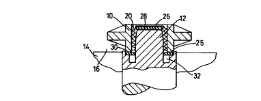
Figure 2 illustrates the method of the invention. A disc 26 of
moulding material is provided within the socket 20, trapped between an
upper end surface 28 of the locating pin 12 and the end wall 22 of the
receptacle. The upper end of the pin 12 has a reduced diameter or lead in
to help in locating the receptacle 10. A second annular washer element 30
of moulding material is provided, trapped against the tooling within the
well 25 under the bottom end portion 24 of the receptacle. In a
conventional manner, uncured rubber material is placed into the mould
cavity 16 (lying over the receptacles 10) . The mould tooling, being at a
temperature of around 140°C, is then closed and the moulding material
within the cavity 16 thereby subjected to pressure. The material becomes
more fluid and completely envelopes the receptacle (insofar as it is
exposed to the mould cavity) . As that is happening, the pressure and
temperature conditions result in the two elements 26,30 of moulding
material associated with the socket 20 becoming fluid, the disc 26 flowing
CA 02310034 2000-OS-15
WO 99/Z5531 - PCT/GB98/03365
6
downwards to fill the socket thread form 18 and the annular socket cavity
between the receptacle and the locating pin 12. The second element 30
makes up any deficiency in volume of the disc 26 within the socket 20 and
also flows into an overflow chamber comprising an annular recess 32
formed in the tool at the root of the locating -pin. Within about ten
minutes after closing the mould cavity the moulding material (both inside
and outside the receptacle) has cured and the mould can be opened for
removal of the product.
As shown in Figure 3, plugs 31 of moulding material are left lining
the sockets of the receptacles 10 when the product is first removed from
the mould. The material which has flowed into the recesses 32 form
convenient gripping collars (handles) 33 which enable the plugs to be
pulled easily out of the sockets 20.
The two elements, disc 26 and washer 30 can be preformed, and
placed on and around the pin 12 before the receptacle 10 is located on the
pin 12. Alternatively, as shown in Figure 4, the elements 26, 30 can be
introduced beneath the receptacle by introducing a thin (e.g. 2mm-3mm)
sheet 34 of uncured moulding material between the receptacle and the
moulding tool 14 as the receptacle is pressed down onto the ~ locating
pin 12. The receptacle 10 and the top surface of the pin 12 are suitably
formed to ensure that the elements are sheared from the sheet. A single
sheet may be used for all the receptacles within the mould cavity. The
mass of sheet remaining within the cavity, after all the receptacles have
been positioned, is taken into account in calculating the additional mass of
material which must then be introduced inta the mould before the mould
is closed. However, if required, the remainder of the sheet 34 may be
removed before moulding takes place. This may be necessary if the insert
10 being moulded in is required to project from the surface of the
CA 02310034 2000-OS-15
WO 991Z553~ ~ PCT/GB98/03365
7
compression moulded article. This will not be the case for a receptacle in
a shoe sole, but may be necessary for a nut in a vehicle door seal, or
other engineering component.
Figure 5 shows another embodiment of the invention, where an
insert 35 with a screw-threaded cavity 36 is to be moulded into a seal
member 37. The mould tooling 14 this time does not have an integral pin
12, but simply the locating tube 23 in which the exterior of the insert 35
is a close fit. It will be noted that the insert 35 projects from the surface
of the seal member 37. In order to locate the insert 35, the locating pin
comprises a cylinder 38 of the moulding material. This is introduced
either into the cavity 36 of the insert or the tooling 14. The tooling 14 is
arranged so that an overflow chamber 39 for the material from the
cylinder 37 is provided underneath the insert 35.
In use, the cylinder 38 and insert 35 are introduced into the mould
16, and then the uncured rubber material. The mould is then closed and
subjected to pressure. The cylinder 38 becomes fluid and fills the cavity
36, forming a plug, with any excess collecting in the overflow chamber
39. . On completion of the moulding process the mouid is opened and the
seal 37 removed. The plugs of moulding material left in the cavity 36 can
then be removed.
The process of the invention can be used for compression moulding
of various different articles requiring hollow inserts, in particular hollow
inserts of plastics material.