Note: Descriptions are shown in the official language in which they were submitted.
CA 02310050 2000-OS-15
-I-
SPECIFICATION
Flowmeter
Technical Field
The present invention relates to a flowmeter for measuring the
quantity of flow of a fluid such as gas and, more particularly, to a flowmeter
capable of accurately measuring a quantity of flow over a wide range of the
quantity of flow.
Background Art
Some flowmeters for measuring the quantity of flow of a fluid such
as gas calculate the quantity of flow by disposing a flow velocity sensor in a
flow path and multiplying the flow velocity obtained by the flow velocity
sensor by the cross-sectional area of the flow path.
Fig. 29 shows a specific configuration of such a conventional
flowmeter. In the flowmeter, a flow velocity sensor 1 is disposed in the
center of a fluid flow path in a pipe 2. A flow quantity calculating unit 3
calculates the quantity of flow by multiplying the flow velocity in the center
of the flow path obtained by the flow velocity sensor 1 by the cross-sectional
area of the pipe 2 and the quantity of flow is displayed on a display unit 4.
In order to maintain the high accuracy in flow quantity measurement by the
flow velocity sensor, the flow velocity sensor 1 has to be disposed in the
most
stable flow of the fluid.
CA 02310050 2000-OS-15
_Z_
The conventional flowmeter has, however, a problem such that a
mounting position of the flow velocity sensor 1 is difficult to be determined
since a drift occurs in the pipe 2 depending on the quantity of flow. It is
necessary to set the flow velocity sensor 1 in a limited range of flow
quantity
where the drift is small. The measurable range of the flow quantity is
accordingly narrowed and it is difficult to accurately measure the flow
quantity of gas over a wide flow quantity range. The drift denotes here
that the flow velocity varies according to places. The flow quantity range
denotes the range of the quantity of flow. The definition will be the same
in the following description.
As described above, in the conventional flowmeter, it is difficult to
set a sufficiently wide flow quantity measurement range by using a single
flow velocity sensor. In order to solve the problem, the following method is
considered. The flow quantity measurement range is divided into, for
example, two ranges of a larger flow quantity range and a smaller flow
quantity r ange. A flow velocity sensor for the range of the larger quantity
of flow is assigned to the range of the larger quantity of flow and a flow
velocity sensor for the range of the smaller quantity of flow is assigned to
the range of the smaller quantity of flow. The quantity of flow is calculated
by switching output signals from the flow velocity sensors.
In the flowmeter constructed by using the plurality of flow velocity
sensors as described above, however, the flow of the fluid is disturbed by the
existence of one of the flow velocity sensor s and there is the possibility
that
the disturbance exerts an adverse influence on the measurement accuracy
CA 02310050 2000-OS-15
-3-
of the other flow velocity sensor. As a result, it is difficult to measure the
quantity of flow with high accuracy over a wide measurement range of the
quantity of flow.
Meanwhile, a gas meter for home use having not only the function
of measuring the quantity of flow of passing gas but also a safety function
realized by mounting a microcomputer is practically used. According to
the safety function, for example, when the quantity of flow of gas equal to or
higher than a predetermined quantity is detected or when a predetermined
gas flow quantity is detected for predetermined time or longer, a gas
emergency trip valve is driven to shut off the gas flow path. By the
functions, a leakage in the pipe, unnatural gas outflow, and the like are
detected, so that an accident can be prevented and the safety can be assured.
For the accurate operation of the functions, however, it is desired to
accurately measure the gas flow quantity over a wide flow quantity range.
Disclosure of Invention
The invention has been achieved in consideration of the above
problems and it is an object of the invention to provide a flowmeter capable
of accurately measuring a quantity of flow of a fluid such as gas over a wide
flow quantity range.
According to the invention, there is provided a flowmeter
comprising: a pipe including a flow path through which a fluid passes and in
which a measurement zone for smaller quantity of flow and a measurement
zone for larger quantity of flow are provided along the longitudinal direction
CA 02310050 2000-OS-15
-4-
of the flow path; a flow path dividing member provided in the measurement
zone for smaller quantity of flow in the flow path of the pipe to divide the
flow path into a plurality of narrower flow paths each having a smaller
cross-sectional area; a first flow velocity sensor provided in the
measurement zone for larger quantity of flow in the flow path of the pipe,
for outputting a signal according to the flow velocity of the fluid passing
through the measurement zone for larger quantity of flow; a second flow
velocity sensor provided in the narrower flow path formed by the flow path
dividing member, for outputting a signal according to the flow velocity of
the fluid passing through the narrower flow path; and flow quantity
calculating means for calculating the quantity of flow on the basis of at
least
one of the output signal of the first flow velocity sensor and the output
signal of the second flow velocity sensor, in accordance with the quantity of
flow.
According to the flowmeter of the invention, a signal responsive to
the flow velocity of the fluid passing through the zone is outputted from the
first flow velocity sensor in the measurement zone for larger quantity of
flow. On the other hand, a signal responsive to the flow velocity of the
fluid passing through the narrower flow path formed by the flow path
dividing member is outputted from the second flow velocity sensor in the
measurement zone for smaller quantity of flow. The flow quantity
calculating means calculates the quantity of flow on the basis of at least one
of the output signal of the fnrst flow velocity sensor and the output signal
of
the second flow velocity sensor in accordance with the quantity of flow. In
CA 02310050 2000-OS-15
-5-
the flowmeter, the scale of the flow velocity distribution in the cross
section
of each narrower flow path (variations in the flow velocity according to
places), that is, the degree of a drift is smaller than that of the flow
velocity
distribution in the cross section of the whole flow path when the flow path
dividing means is not disposed. The flow velocity in the narrower flow
path near the flow path wall becomes higher as compared with the case
where no flow path dividing means is provided.
According to the flowmeter of the invention, the first flow velocity
sensor may be attachable to and detachable from the wall face of the pipe.
The second flow velocity sensor may be also attachable to and detachable
from the wall face of the pipe.
According to the flowmeter of the invention, the second flow
velocity sensor may be disposed in the narrower flow path which is the
closest to the wall face of the pipe among the plurality of narrower flow
paths. The first flow velocity sensor may be disposed near the wall face of
the pipe.
In the flowmeter of the invention, the plurality of first flow velocity
sensors may further comprise mean flow velocity calculating means for the
measurement zone for larger quantity of flow, which calculates a mean
value of the flow velocities in the measurement zone for larger quantity of
flow on the basis of the output signals of the plurality of first flow
velocity
sensors and outputs the mean value to the flow quantity calculating means.
In the flowmeter of the invention, the plurality of second flow
velocity sensors may further comprise mean flow velocity calculating means
CA 02310050 2000-OS-15
for the measurement zone for smaller quantity of flow, which calculates a
mean value of the flow velocities in the measurement zone for smaller
quantity of flow on the basis of the output signals of the plurality of second
flow velocity sensors and outputs the mean value to the flow quantity
calculating means.
The flowmeter of the invention may still further comprise a mesh-
like flow regulating member in the flow path.
Another flowmeter of the invention further comprises flow velocity
increasing means for increasing the flow velocity of the fluid passing
through the narrower flow path in which the second flow velocity sensor is
provided.
In the flowmeter, the flow velocity increasing means increases the
flow velocity of the fluid passing through the narrower flow path in which
the second flow velocity sensor is provided. The flow velocity increasing
means can be constructed so as to increase the flow velocity of the fluid
passing through the narrower flow path by decreasing the space capacity
around the second flow velocity sensor in the narrower flow path. The flow
velocity increasing means can be constructed by a pair of column-shaped
members which are provided upright on both sides of the second flow
velocity sensor. The pair of column-shaped members as the flow velocity
increasing means may be provided upright on both sides of the second flow
velocity sensor in such a manner that the interval between the pair of
column-shaped members is widened toward the upstream of the flow path.
The second flow velocity sensor may be integrated into a sensor unit with
CA 02310050 2000-OS-15
_7_
the pair of column-shaped members as the flow velocity increasing means
and the sensor unit may be attachable to and detachable from the wall face
of the pipe. At least a part of the pair of column-shaped members as the
flow velocity increasing means has a streamline shape along the direction of
the flow of the fluid, or the pair of column-shaped members as the flow
velocity increasing means may be upright columns each having a cross
section of a wing shape.
According to the flowmeter, the plurality of first flow velocity
sensors may further comprise mean flow velocity calculating means for the
measurement zone for larger quantity of flow, which calculates a mean
value of the flow velocities in the measurement zone for larger quantity of
flow on the basis of the output signals of the plurality of first flow
velocity
sensors and outputs the mean value to the flow quantity calculating means.
The plurality of second flow velocity sensors may further comprise mean
flow velocity calculating means for the measurement zone for smaller
quantity of flow, which calculates a mean value of the flow velocities in the
measurement zone for smaller quantity of flow on the basis of the output
signals of the plurality of second flow velocity sensors and outputs the mean
value to the flow quantity calculating means.
According to the flowmeter, the second flow velocity sensor may be
disposed in the narrower flow path which is closest to the wall face of the
pipe among the plurality of narrower flow paths. The first flow velocity
sensor may be disposed near the wall face of the pipe.
The flowmeter may further comprise a mesh-like flow regulating
CA 02310050 2000-OS-15
_g_
member in the flow path.
According to the invention, there is provided a further another
flowmeter comprising: a plurality of flow velocity sensors provided in a flow
path through which a fluid passes, for outputting signals according to the
flow velocity of the fluid; and flow quantity calculating means for
calculating the quantity of flow on the basis of at least one of the output
signals of the plurality of flow velocity sensors in accordance with the
quantity of flow, wherein each of the plurality of flow velocity sensors is
prevented from being influenced by the disturbed flow of the fluid caused by
the existence of another flow velocity sensor.
In the flowmeter, since each of the plurality of flow velocity sensors
is not influenced by the disturbed flow of the fluid caused by the existence
of
another flow velocity sensor, a stable output signal can be obtained from
each of the flow velocity sensors. The quantity of flow is calculated on the
basis of at least one of the output signals, so that stable measurement of the
quantity of flow can be realized.
According to the flowmeter, the plurality of flow velocity sensors
are disposed out of on a straight line along the direction of the flow of the
fluid, thereby eliminating the influence of the disturbed flow of the fluid.
In this case, the flow disturbed by the existence of the flow velocity sensor
on the upstream side does not reach the flow velocity sensor on the
downstream side, so that the output signal from the flow velocity sensor on
the downstream side is stabilized.
In the flowmeter, in the case where a flow velocity distribution in a
CA 02310050 2000-OS-15
flow path cross section perpendicular to the direction of the flow of the
fluid
is nonuniform in the direction along the circumferential face of flow path
walls forming the flow path, preferably, one of the plurality of flow velocity
sensors is disposed in the maximum flow velocity position in the flow
velocity distribution in the direction along the circumferential face of the
flow path wall. In this case, the flow velocity sensor disposed in the
maximum flow velocity position can detect the flow velocity with high
sensitivity. "The case where a flow velocity distribution in a flow path
cross section perpendicular to the direction of the flow of the fluid is
nonuniform in the direction along the circumferential face of flow path walls
forming the flow path", generally, corresponds to the case where the cross
sectional shape of the flow path is not circular.
In the flowmeter, holding units each for holding each of the flow
velocity sensors are smoothly embedded in flow path walls forming the flow
path without any gap and step, thereby suppressing a disturbance of the
flow of the fluid. In this case, since the boundary between the holding
units of the flow velocity sensor and the flow path wall is smoothed, when
the gas passes there, the flow is not easily disturbed and the influence of
the
disturbed flow on the other flow velocity sensor is a little.
In the flowmeter, when the positional relation among the plurality
of flow velocity sensors is such that one of them is on the upstream side and
the other is on the downstream side, it is preferable to further dispose a
first
mesh-like flow regulating member in the flow path between the flow
velocity sensors. According to the flowmeter, the flow of the fluid passed
CA 02310050 2000-OS-15
-1~-
through the flow velocity sensor is regulated by the action of the first mesh-
like flow regulating member provided for the flow path between the flow
velocity sensors, so that the other fluid sensors are not easily influenced by
the disturbed flow.
The flowmeter can be also constructed in such a manner that a part
of the plurality of flow velocity sensors is disposed on the upstream side in
the flow path, the other flow velocity sensors are disposed on the
downstream side in the flow path, and the flow quantity calculating means
calculates the quantity of flow in the range of the larger quantity of flow on
the basis of output signals of the part of the flow velocity sensors on the
upstream side and calculates the quantity of flow in the range of the smaller
quantity of flow on the basis of output signals of the other flow velocity
sensors on the downstream side. In the flowmeter, the quantity of flow in
the range of the larger quantity of flow is calculated on the basis of output
signals from the flow velocity sensors disposed upstream and the quantity of
flow in the range of the smaller quantity of flow is calculated on the basis
of
the output signals from the flow velocity sensors disposed on the
downstream side. In the range of the smaller quantity of flow, the
influence of the disturbed flow caused by the existence of the flow velocity
sensors on the upstream side is not easily exerted on the flow velocity
sensors on the downstream side. Consequently, an output signal from the
flow velocity sensor disposed on the downstream side is not unstable.
According to the flowmeter, a flow path dividing member for
dividing the flow path into a plurality of narrower flow paths each having a
CA 02310050 2000-OS-15
-11-
smaller cross-sectional area may be further disposed in the flow path.
In the flowmeter, a second mesh-like flow regulating member may
be further disposed in the flow path on the upstream side of the plurality of
flow velocity sensors. In the flowmeter, at least the flow of the fluid
passing through the flow velocity sensor on the most upstream side is
regulated by the action of the second mesh-like flow regulating member.
In the flowmeter, at least a part of the plurality of flow velocity
sensors may be disposed near the wall face of the flow path.
Other and further objects, features and advantages of the invention
will appear more fully from the following description.
Brief Description of Drawings
Fig. 1 is a longitudinal cross section showing a schematic
configuration of a flowmeter according to a first embodiment of the
invention.
Fig. 2 is a cross section in the direction which perpendicularly
crosses the longitudinal direction of the flowmeter of Fig. 1.
Fig. 3 is a block diagram showing the circuit configuration of the
flowmeter of Fig. 1.
Fig. 4 is an explanatory diagram schematically showing a
distribution of flow velocities in a flow path when a regulating strainer is
attached in the flowmeter.
Fig. 5 is an explanatory diagram schematically showing a
distribution of flow velocities in a flow path when a regulating strainer is
CA 02310050 2000-OS-15
-12-
not attached in the flowmeter.
Fig. 6 is a longitudinal cross section schematically showing the
construction of a flowmeter according to a second embodiment of the
invention.
Fig. 7 is a cross section in the dir ection which perpendicularly
crosses the longitudinal direction in the flowmeter of Fig. 6.
Fig. 8 is a perspective view of an example of a detailed
configur ation of a nozzle in the flowmeter shown in Fig. 6.
Fig. 9 is a plan view showing the action of the nozzle illustrated in
Fig. 8.
Fig. 10 is an explanatory diagram showing an example of the
relation between sensor output values of a flow velocity sensor for a smaller
quantity of flow of the flowmeter illustrated in Fig. 6 and measurement
conditions.
Fig. 11 is a plan view of a modification of the nozzle in the
flowmeter shown in Fig. 6.
Fig. 12 is a plan view of another modification of the nozzle in the
flowmeter shown in Fig. 6.
Fig. 13 is a plan view of further another modification of the nozzle
in the flowmeter shown in Fig. 6.
Fig. 14 is an explanatory diagram showing an example of the
relation between sensor outputs and installing positions of the flow velocity
sensor for smaller quantity of flow in the flowmeter illustrated in Fig. 6.
Fig. 15 is a longitudinal cross section of a flowmeter accor ding to a
CA 02310050 2000-OS-15
-13-
third embodiment of the invention.
Fig. 16 is a plan view of the flowmeter shown in Fig. 15.
Fig. 17 is a cross section in the direction which perpendicularly
crosses the longitudinal direction of the flowmeter shown in Fig. 15.
Fig. 18 is a block diagram showing a circuit configuration of the
flowmeter of Fig. 15.
Fig. 19 is a plan view of the flowmeter according to a fourth
embodiment of the invention.
Fig. 20 is a cross section in the direction which perpendicularly
crosses the longitudinal direction of the flowmeter shown in Fig. 19.
Fig. 21 is a plan view of a flowmeter as a modification of the fourth
embodiment of the invention.
Fig. 22 is a cross section in the direction which perpendicularly
crosses the longitudinal direction of the flowmeter shown in Fig. 21.
Fig. 23 is a cross section in the direction which perpendicularly
crosses the longitudinal direction of a flowmeter as another modification of
the fourth embodiment of the invention.
Fig. 24 is a cross section in the direction which perpendicularly
crosses the longitudinal direction of a flowmeter as further another
modification of the fourth embodiment of the invention.
Fig. 25 is a longitudinal cross section of a flowmeter according to a
fifth embodiment of the invention.
Fig. 26 is a cross section in the direction which perpendicularly
crosses the longitudinal direction of the flowmeter shown in Fig. 25.
CA 02310050 2000-OS-15
-14-
Fig. 27 is a longitudinal cross section of a flowmeter according to a
sixth embodiment of the invention.
Fig. 28 is a plan view of the flowmeter shown in Fig. 27.
Fig. 29 is a cross section showing a schematic configuration of a
conventional flowmeter.
Best Mode for Carrying Out the Invention
Embodiments of the invention will be described in detail
hereinbelow with reference to the drawings.
[First Embodiment]
With reference to Figs. 1 to 5, a first embodiment of the invention
will be described.
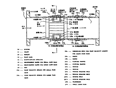
Fig. 1 shows the configuration in longitudinal cross section of a
flowmeter according to an embodiment of the invention. Fig. 2 shows the
configuration in cross section taken along line II-II of Fig. 1. The
flowmeter according to the embodiment is used as a gas meter. This
flowmeter l0A comprises a pipe 10 having an inlet 11 for receiving a gas 20
and an outlet 12 for exhausting the gas 20. The diameter of a flow path 13
in the pipe 10 is, for example, 50 mm. In the flow path 13, along the
longitudinal direction, a measurement zone 15 for smaller quantity of flow
on the upstream side and a measurement zone 16 for larger quantity of flow
on the downstream side are provided. In the measurement zone 15 for
smaller quantity of flow, a regulating strainer 14 for regulating and
straightening the flow of the gas 20 and suppressing occurrence of a drift is
CA 02310050 2000-OS-15
-15-
provided. The regulating strainer 14 corresponds to an example of "flow
path dividing member" in the invention.
As shown in Fig. 2, by partitions, the regulating strainer 14
partitions the flow path 13 in the measurement zone 15 for smaller quantity
of flow into a plurality of narrower flow paths 14A each having a cross-
section area smaller than that of the flow path 13. The gas 20 flows
through the divided narrower flow paths 14A. The shape in cross section of
the narrower flow path 14A may be not only the triangular shape as shown
in Fig. 2 but also another shape such as a rectangular shape, a wave shape,
or a hexagonal shape.
In the pipe 10 in the measurement zone 15 for smaller quantity of
flow, insertion units 17a and 17b for flow velocity sensors for smaller
quantity of flow are provided so as to face each other (in the upper and lower
positions in the diagram). In the insertion units 17a and 17b for velocity
sensors for smaller quantity of flow, flow velocity sensors 15a and 15b for
smaller quantity of flow held by sensor holding units 151a and 151b are fit,
respectively. A sensing part (not shown) at the tip of each of the flow
velocity sensors 15a and 15b for smaller quantity of flow faces the center
part of the narrower flow path 14A which is the closest to the wall face
among the plurality of narrower flow paths 14A formed by the regulating
strainer 14.
On the other hand, in the pipe 10 in the measurement zone 16 for
larger quantity of flow, insertion units 18a and 18b for flow velocity sensors
for larger quantity of flow are provided so as to face each other (in the
upper
CA 02310050 2000-OS-15
-16-
and lower positions in the diagr am). In the insertion units 18a and 18b for
flow velocity sensors for larger quantity of flow, flow velocity sensors 16a
and 16b for larger quantity of flow as first flow velocity sensors are fit in
a
state where they are held by sensor holding units 161a and 161b,
respectively.
The flow velocity sensor s 15a and 15b for smaller quantity of flow
are used to measure the quantity of flow in the range of the smaller
quantity of flow and the flow velocity sensors 16a and 16b for larger
quantity of flow are used to measure the quantity of flow in the range of the
larger quantity of flow. Each of the flow velocity sensors 15a and 15b for
smaller quantity of flow corresponds to an example of "second flow velocity
sensor" in the invention and each of the flow velocity sensors 16a and 16b
for lar ger quantity of flow corresponds to an example of "first flow velocity
sensor" in the invention.
Each of the flow velocity sensors 15a and 15b for smaller quantity
of flow and the flow velocity sensors 16a and 16b for larger quantity of flow
has, for example, although not shown, a heating unit and two temperature
sensors disposed on the upstream and downstream sides of the heating unit.
In this case, the quantity of flow corresponding to the flow velocity can be
obtained from a power supplied to the heating unit necessary to keep the
difference between the temperatures sensed by the two temperature sensors
constant or the flow velocity can be obtained from the difference between
the temperatures sensed by the two temperature sensors by heating the
heating unit with a constant current or constant power.
CA 02310050 2000-OS-15
-17-
The flow path 13 on the upstream side of the flow velocity sensors
15a and 15b for smaller quantity of flow is provided with a gauze 19a for
regulating and straightening the flow and the flow path 13 between the flow
velocity sensors 15a and 15b for smaller quantity of flow and the flow
velocity sensors 16a and 16b for larger quantity of flow is provided with a
gauze 19b for regulating and straightening the flow. For example, #100
mesh or the like is used as each of the gauzes 19a and 19b.
Fig. 3 shows the circuit configuration of a gas meter to which the
flowmeter l0A is applied. The circuit comprises: a mean flow velocity
calculating unit 41 for calculating a mean value of the flow velocities in the
narrower flow paths 14A formed by the regulating strainer 14 on the basis
of output signals from the flow velocity sensors 15a and 15b for smaller
quantity of flow; and a mean flow velocity calculating unit 42 for calculating
a mean value of the flow velocities in the measurement zone 16 for larger
quantity of flow on the basis of output signals from the flow velocity sensors
16a and 16b for larger quantity of flow. The circuit also comprises: a signal
switching unit 43 for selecting one of the output of the mean flow velocity
calculating unit 41 and the output of the mean flow velocity calculating unit
42 in accordance with the quantity of flow; a display unit 45 for displaying
the quantity of flow of the gas and an integrated quantity of flow on the
basis of the output of the signal switching unit 43; and an external output
terminal 46 for outputting the quantity of flow calculated by the quantity of
flow calculating unit 44 and an integrated quantity of flow to the outside.
Mainly, the mean flow velocity calculating units 41 and 42 and the flow
CA 02310050 2000-OS-15
-1g-
quantity calculating unit 44 correspond to an example of " flow quantity
calculating means" in the invention.
The signal switching unit 43 outputs the output of the mean flow
velocity calculating unit 41 to the flow quantity calculating unit 44 when
the quantity of flow calculated by the flow quantity calculating unit 44 is in
a preset range of the smaller quantity of flow. The signal switching unit 43
outputs the output of the mean flow velocity calculating unit 42 to the flow
quantity calculating unit 44 when the quantity of flow calculated by the
flow quantity calculating unit 44 is in a preset range of the larger quantity
of flow. When the quantity of flow is in the preset range of the smaller
quantity of flow, the flow quantity calculating unit 44 calculates the
quantity of flow by multiplying the mean value of the flow velocities as an
output of the mean flow velocity calculating unit 41 by a pipe shape
coefficient corresponding to the narrower flow path 14A in the regulating
strainer 14. When the quantity of flow is in the preset range of the larger
quantity of flow, the flow quantity calculating unit 44 calculates the
quantity of flow by multiplying the mean value of the flow velocities as an
output of the mean flow velocity calculating unit 42 by the pipe shape
coefficient corresponding to the flow path 13 on the downstream side of the
regulating strainer 14.
In the case where the range of the smaller quantity of flow and the
range of the larger quantity of flow are partially overlapped with each other
and the quantity of flow becomes higher, when the quantity of flow reaches
the upper limit of the overlapped range, the quantity of flow may be
CA 02310050 2000-OS-15
-19-
calculated by switching the output of the mean flow velocity calculating unit
41 to the output of the mean flow velocity calculating unit 42. In the case
where the quantity of flow goes low, when the quantity of flow reaches the
lower limit of the overlapped range, the quantity of flow may be calculated
by switching the output of the mean flow velocity calculating unit 42 to the
output of the mean flow velocity calculating unit 41. Each of the mean
flow velocity calculating units 41 and 42, signal switching unit 43, and flow
quantity calculating unit 44 can be constructed by, for example, a
microcomputer.
The actions of the flowmeter l0A having the configuration as
described above and the gas meter to which the flowmeter l0A is applied
will now be described.
The gas 20 taken from the inlet 11 first passes through each of the
plug ality of narrower flow paths 14A in the regulating str ainer 14 in the
measurement zone 15 for smaller quantity of flow. At this time, each of
the flow velocity sensors 15a and 15b for smaller quantity of flow outputs a
signal according to the flow velocity of the gas 20. The gas 20 which has
passed the measurement zone 15 for smaller quantity of flow passes
through the measurement zone 16 for larger quantity of flow and is
exhausted from the outlet 12. At that time, each of the flow velocity
sensors 16a and 16b for lar ger quantity of flow outputs a signal according to
the flow velocity of the gas 20 passing through the measurement zone 16 for
larger quantity of flow.
The mean flow velocity calculating unit 41 calculates the mean
CA 02310050 2000-OS-15
-20-
value of the flow velocities in the narrower flow paths 14A on the basis of
output signals of the flow velocity sensors 15a and 15b for smaller quantity
of flow in the narrower flow paths 14A in the regulating strainer 14. The
mean flow velocity calculating unit 42 calculates the mean value of the flow
velocities in the measurement zone 16 of larger quantity of flow on the basis
of output signals of the flow velocity sensors 16a and 16b for larger quantity
of flow in the measurement zone 16 for larger quantity of flow. The signal
switching unit 43 outputs the output of the mean flow velocity calculating
unit 41 to the flow quantity calculating unit 44 when the quantity of flow
calculated by the flow quantity calculating unit 44 is in the preset range for
smaller quantity of flow. The signal switching unit 43 outputs the output
of the mean flow velocity calculating unit 42 to the flow quantity calculating
unit 44 when the quantity of flow calculated by the flow quantity
calculating unit 44 is in the preset range of the larger quantity of flow.
The flow quantity calculating unit 44 calculates the quantity of flow and the
integrated quantity of flow on the basis of the mean value of the flow
velocities as an output of the mean flow velocity calculating unit 41 when
the quantity of flow is in the preset range for smaller quantity of flow. The
flow quantity calculating unit 44 calculates the quantity of flow and the
integrated quantity of flow on the basis of the mean value of the flow
velocities as an output of the mean flow velocity calculating unit 42 when
the quantity of flow is in the preset range of the lar ger quantity of flow.
The integrated quantity of flow calculated by the flow quantity calculating
unit 44 is displayed on the display unit 45. It is also possible to partially
CA 02310050 2000-OS-15
-Z 1-
overlap the range of the smaller quantity of flow and the range of the larger
quantity of flow, obtain the mean value of the quantity of flow calculated on
the basis of the mean value of the flow velocities as an output of the mean
flow velocity calculating unit 41 and the quantity of flow calculated on the
basis of the mean value of the flow velocities as an output of the mean flow
velocity calculating unit 42 and use the obtained mean value as a measured
quantity of flow.
The characteristic action of the invention will now be described.
Figs. 4 and 5 are used to explain the difference between a flow
velocity distribution when the regulating strainer 14 is used and that when
the regulating strainer 14 is not used. Fig. 4 shows a flow velocity
distribution 30 when the regulating strainer 14 is disposed as in the
embodiment. Fig. 5 shows a flow velocity distribution 31 in the flow path
13 when no regulating strainer 14 is used as a comparative example.
Generally, the flow velocities are distributed in such a manner that
the flow velocity is the fastest in the center of the flow path and becomes
slower toward the wall face and what is called a drift occurs. Particularly,
the degree of a drift is high in the range of the smaller quantity of flow.
Even when the flow is detected in the flow path center part, there is the case
such that a flow is not detected near the wall face of the flow path.
Specifically, the flow velocity distribution in the flow path 13 when the
regulating strainer 14 is not provided in the measurement zone 15 for
smaller quantity of flow is, for example, as shown in Fig. 5. In the diagram,
the length of the arrow 31 shows the degree of the flow velocity. As shown
CA 02310050 2000-OS-15
-22-
in the diagram, when the flow velocity sensors 15a and 15b for smaller
quantity of flow are attached to the wall face, the flow velocity sensors 15a
and 15b for smaller quantity of flow measure the slowest flow velocity in the
flow velocity distribution 31. Depending on the quantity of flow, there is a
case such that the flow velocity cannot be detected. The flow quantity
measurable range, especially on the lower limit side, is therefore narrowed.
On the contrary, when the regulating strainer 14 is provided as
shown in Fig. 4, each of the narrower flow paths 14A defined by the
regulating strainer 14 has the flow velocity distribution 30 in which the flow
velocity is fast in the center but slow in the peripheral part. Moreover,
there is hardly any difference between the mean flow velocity in the
narrower flow path 14A in the center of the flow path 13 and that in the
narrower flow path 14A in the peripheral part. That is, the mean flow
velocity in the narrower flow path 14A closest to the wall face of the pipe 10
in the case where the regulating strainer 14 is provided is considerably
faster than that near the wall face of the pipe 10 in the case where the
regulating strainer 14 is not provided (Fig. 5). The measurement
sensitivity of the flow velocity sensors 15a and 15b for smaller quantity of
flow in Fig. 4 is higher than that of the flow velocity sensors 15a and 15b
for
smaller quantity of flow in Fig. 5. Thus, the quantity of flow measurable
range on the lower limit side is expanded.
More specifically, as described above, when the sensing part at the
tip of each of the flow velocity sensors 15a and 15b for smaller quantity of
flow is disposed so as to be positioned around the center of the narrower
CA 02310050 2000-OS-15
-23-
flow path 14A which is the closest to the wall face of the pipe 10, the peak
value of the flow velocity distribution 30 in the narrower flow path is
detected. Consequently, the measurement sensitivity is further improved
and the measurable range of the quantity of flow on the lower limit side is
further enlarged.
Even when the flow velocity sensor 1 (Fig. 29) is not disposed in the
center part of the flow path as in the conventional technique but the flow
velocity sensors 15a and 15b for smaller quantity of flow are disposed on or
near the wall face of the pipe 10, sufficient measurement sensitivity can be
obtained and the measurable range of the quantity of flow can be
sufficiently assured.
Since the flow velocity sensors 16a and 16b for larger quantity of
flow disposed in the measurement zone 16 for larger quantity of flow are
used to measure the flow velocity of the gas in the range of the larger
quantity of flow, their measurement sensitivity is assured. The gauze 19b
for regulating the flow is disposed on the immediate upstream side of the
measurement zone 16 for larger quantity of flow, so that a disturbed flow is
suppressed. The regulating strainer is not therefore especially needed in
the measurement zone 16 for larger quantity of flow. As necessary, the
regulating strainer can be disposed also in the measurement zone 16 for
larger quantity of flow.
As mentioned above, in the flowmeter according to the embodiment,
the flow velocity sensors 15a and 15b for smaller quantity of flow are
disposed in the narrower flow paths 14A divided by the regulating strainer
CA 02310050 2000-OS-15
-24-
14 and the detecting part at the tip of each of the flow velocity sensors 15a
and 15b for smaller quantity of flow is positioned in the center part of the
narrower flow path 14A, so that the flow velocity measurement with high
sensitivity can be performed also in the range of the smaller quantity of
flow.
The mounting position of the flow velocity sensor is not limited to a part
around the center of the flow path even in the range of the smaller quantity
of flow in which a drift easily occur substantially unlike in the conventional
technique, but the mounting position can be arbitrarily selected. That is,
even when the flow velocity sensor is disposed near the pipe wall to which
the mounting is easy, the smaller quantity of flow does not become
insensible. The measurable range of the quantity of flow can be
substantially enlarged. Since the occurrence of the disturbed flow in the
space in which the flow velocity sensors 15a and 15b for smaller quantity of
flow are disposed is suppressed by the flow regulating action of the
regulating strainer 14 and the gauze 19a, the accuracy of the quantity of
flow measurement is improved.
When the flowmeter is applied to the gas meter, high-accuracy
measurement can be realized over a wide range of the quantity of flow from
the range of the smaller quantity of flow to the range of the larger quantity
of flow. Especially, when the flowmeter is applied to a gas meter having
the safety function which senses an abnormal gas using state and
preventing an accident, the accurate operation of the safety function can be
assured.
In the embodiment, by providing the regulating strainer 14, the
CA 02310050 2000-OS-15
-25-
flow velocity sensors 15a and 15b for smaller quantity of flow can be
disposed on or very close to the wall face of the pipe 10 while assuring the
sensitivity of the flow velocity measurement. Consequently, each of the
sensors can be relatively easily formed in a detachable sensor unit. When
such a detachable sensor unit is used, the line connection between each of
the sensors and the measurement circuit part of the gas meter body
becomes easier. Further, when a trouble occurs, for example, in any of the
flow velocity sensors 15a and 15b for smaller quantity of flow, the flow
velocity sensors 16a and 16b for larger quantity of flow, and the like, it is
sufficient to replace only the sensor unit without disassembling the whole
flow path 13, so that the maintainability is improved. This point is similar
with respect to the flow velocity sensors 16a and 16b for larger quantity of
flow.
[Second Embodiment)
With reference to Figs. 6 to 14, a second embodiment of the
invention will be described.
Fig. 6 shows the configuration in longitudinal cross section of a
flowmeter according to a second embodiment of the invention. Fig. 7 shows
the configuration in cross section taken along line VII-VII of Fig. 6. The
same reference numerals are designated to the same components as those
shown in Figs. 1 and 2 and the description is omitted here as appropriate.
In a flowmeter 10B according to the embodiment, sensor units 150a and
150b including the flow velocity sensors 15a and 15b for smaller quantity of
flow as second flow velocity sensors are detachably fit in the insertion units
CA 02310050 2000-OS-15
-26-
17a and 17b for flow velocity sensors for smaller quantity of flow. In the
regulating strainer 14, for example, fitting grooves 21a and 21b each having
the depth of about 15 mm and the length in the longitudinal direction of
about 27 mm are provided in parts corresponding to the fitting parts in the
sensor units 150a and 150b.
The sensor unit 150a includes a nozzle 22a as a flow velocity
increasing means for increasing the flow velocity of the gas 20 passing
through the narrower flow path 14A for which the flow velocity sensor 15a
for smaller quantity of flow is provided, a nozzle holding unit 23a for
holding the nozzle 22a, and a sensor holding unit 151a for holding the flow
velocity sensor 15a for smaller quantity of flow. The sensor unit 150b
includes a nozzle 22b as a flow velocity increasing means for increasing the
flow velocity of the gas 20 passing through the narrower flow path 14A for
which the flow velocity sensor 15b for smaller quantity of flow is provided, a
nozzle holding unit 23b for holding the nozzle 22b, and a sensor holding unit
151b for holding the flow velocity sensor 15b for smaller quantity of flow.
In the sensor unit 150a, all of the nozzle 22a, nozzle holding unit
23a, flow velocity sensor 15a for smaller quantity of flow, and sensor
holding unit 151a are integrally formed. In the sensor unit 150b, all of the
nozzle 22b, nozzle holding unit 23b, flow velocity sensor 15b for smaller
quantity of flow, and sensor holding unit 151b are integrally formed. By
constructing each of the sensor units 150a and 150b by integrating the
elements as mentioned above and detachably attaching the sensor units
150a and 150b to the insertion units 17a and 17b for flow velocity sensors
CA 02310050 2000-OS-15
-27-
for smaller quantity of flow, the attachment/detachment of the elements
to/from the pipe 10 is facilitated. All of the elements of each of the sensor
units 150a and 150b may not be integrated and each of them can be
constructed so as to be separated.
The flow velocity sensors 15a and 15b for smaller quantity of flow
are constructed so that the sensing part at the tip of each of the sensors 15a
and 15b is located in the center part of the narrower flow path 14A which is
the closest to the wall face among the plurality of narrower flow paths 14A
defined by the regulating strainer 14. The nozzles 22a and 22b are
positioned in the fitting grooves 21a and 21b formed in the regulating
strainer 14. As shown in Fig. 8 which will be described hereinlater, each of
the nozzles 22a and 22b has a shape such that the space capacity in each of
the fitting grooves 21a and 21b gradually decreases from the upstream side
towards the downstream side. That is, the space capacity around each of
the flow velocity sensors 15a and 15b for smaller quantity of flow in the
narrower flow path 14A gradually decreases from the upstream side
towards the downstream side, thereby enabling the flow velocity of the gas
20 passing through the narrower flow path 14A to be increased.
Figs. 8 and 9 are explanatory diagrams showing an example of the
detailed configuration of each of the nozzles 22a and 22b. As shown in the
diagrams, each of the nozzles 22a and 22b is comprised of a pair of column-
shaped members provided upright on both sides of each of the flow velocity
sensors 15a and 15b for smaller quantity of flow. The pair of column-
shaped members constructing each of the nozzles 22a and 22b are provided
CA 02310050 2000-OS-15
_28_
upright on both sides of each of the flow velocity sensors 15a and 15b for
smaller quantity of flow so that the interval between front end parts 51 of
the members is gradually widened toward the upstream of the narrower
flow path 14A. Consequently, it makes the gas 20 whose flow velocity is
increased easily pass between the pair of column-shaped members. The
height of each of the nozzles 22a and 22b is, for example, about 10 mm. As
a material of the nozzles 22a and 22b, for example, a metal such as
aluminium or stainless steel, resin, or the like is applied.
It is preferable that at least the inside (the side to which the flow
velocity sensor 15a or 15b for smaller quantity of flow is provided) of the
front end part 51 or the rear end part 52 of each of the nozzles 22a and 22b
has a streamline shape. By streamlining the front end part 51, as shown
in Fig. 9, the gas 20 is easily led through the nozzle 22a or 22b and it makes
the flow velocity of the gas 20 easily increase. By streamlining the rear
end parts 52, the gas 20 led between the nozzle 22a or 22b easily passes
through the rear end parts 52 so that it prevents the gas 20 from being
stagnated in the rear end parts 52.
The other
configurations of the flowmeter lOB are similar to those of the first
embodiment. The configuration of the circuit part of the gas meter to
which the flowmeter 10B according to the embodiment is applied is similar
to the circuit configuration (Fig. 3) in the first embodiment. In the second
embodiment, however, when the quantity of flow is in the preset range of
the smaller quantity of flow, the flow quantity calculating unit 44 calculates
CA 02310050 2000-OS-15
-29-
the quantity of flow by multiplying the mean value of the flow velocities as
an output of the mean flow velocity calculating unit 41 by not only the pipe
shape coefficient corresponding to the narrower flow path 14A in the
regulating strainer 14 but also a correction coefficient corresponding to the
shape of the nozzle 22a or 22b.
The action of the flowmeter lOB according to the embodiment will
now be explained.
The gas 20 supplied from the inlet 11 first passes through the
plurality of narrower flow paths 14A in the regulating strainer 14 in the
measurement zone 15 for smaller quantity of flow. At this time, the
regulating strainer 14 acts in a manner similar to the case of the first
embodiment (Fig. 4) to increase the flow velocity near the pipe wall. A part
of the gas 20 passing through the plurality of narrower flow paths 14A
reaches the nozzles 22a and 22b provided upright on both sides of the flow
velocity sensors 15a and 15b for smaller quantity of flow. When the gas 20
reaches the nozzles 22a and 22b, the flow velocity of the gas 20 is increased
by the action of the nozzles 22a and 22b. The gas 20 whose flow velocity is
increased passes through the flow velocity sensors 15a and 15b for smaller
quantity of flow provided in the center of the nozzles 22a and 22b,
respectively, on the inner wall surface of the flow path 13. At this time, the
flow velocity sensors 15a and 15b for smaller quantity of flow output signals
according to the flow velocity of the gas 20 increased by the nozzles 22a and
22b. The gas 20 which passed through the measurement zone 15 for
smaller quantity of flow passes through the measurement zone 16 for larger
CA 02310050 2000-OS-15
-30-
quantity of flow and is exhausted from the outlet 12. At this time, the flow
velocity sensors 16a and 16b for larger quantity of flow output signals
according to the flow velocity of the gas 20 passing through the
measurement zone 16 for larger quantity of flow. Since the operation
related to subsequent signal processes is similar to that of the case of the
first embodiment, its description is omitted here.
Fig. 10 is an explanatory diagr am showing an example of the
sensor output value measured when changing the measurement conditions
in the flow velocity sensors 15a and 15b for smaller quantity of flow. In the
diagram, the measurement results obtained when the measurement
conditions are changed in four ways are shown. Measurement conditions
B to D denote the case where the nozzles 22a and 22b are provided near the
flow velocity sensors 15a and 15b for smaller quantity of flow and the flow
velocity is measured. A measurement condition A denotes the case where
the flow velocity is measured without providing the nozzles 22a and 22b
(corresponding to the case where the height of each of the nozzles 22a and
22b is 0).
In the measurement conditions B to D, the cases where the nozzle
22a whose height is about 10 mm and the nozzle 22b whose height is about
7 mm from the sensing parts of the flow velocity sensors 15a and 15b for
smaller quantity of flow are fit in the fitting grooves 21a and 21b having the
depth of about 11.5 mm from the sensing parts of the flow velocity sensors
15a and 15b for smaller quantity of flow are shown. That is, according to
the measurement conditions B to D, the nozzle 22a having the height of
CA 02310050 2000-OS-15
-31-
about 10 mm is attached near the flow velocity sensor 15a for smaller
quantity of flow and the nozzle 22b having the height of about 7 mm is
attached near the other flow velocity sensor 15b for smaller quantity of flow.
Under the measurement condition D, sensor output values of the flow
velocity sensors 15a and 15b for smaller quantity of flow are simultaneously
observed. Under the measurement condition C, by closing the flow velocity
sensor 15b for smaller quantity of flow to which the nozzle 22b is attached
with a closing lid, the sensor output value from the flow velocity sensor 15a
for smaller quantity of flow to which the nozzle 22a having the height of
about 10 mm is attached is observed. Under the measurement condition B,
by closing the flow velocity sensor 15a for smaller quantity of flow to which
the nozzle 22a is attached with a closing lid, a sensor output value from the
flow velocity sensor 15b for smaller quantity of flow to which the nozzle 22b
having the height of about 7 mm is attached is observed. In any of the
measurement conditions A to D, the gas 20 used for measurement is air and
the diameter of the flow path 13 in the pipe 10 is about 56 mm. When the
gas 20 with a very low quantity of flow (quantity of flow corresponding to 5
litters per hour) is introduced, the sensor output value shown in Fig. 10
indicates a value of a net pulse outputted from the flow velocity sensors 15a
and 15b for smaller quantity of flow.
It is understood from the measurement results shown in Fig. 10
that, when the nozzles 22a and 22b are not provided (measurement
condition A), the gas 20 with a very low quantity of flow cannot be detected
by the flow velocity sensors 15a and 15b for smaller quantity of flow (sensor
CA 02310050 2000-OS-15
-32-
output value is 0). On the contrary, when the nozzles 22a and 22b are
provided (measurement conditions B to D), sensor outputs of over 7 pulses
are produced and the flow velocity of the gas 20 with even a very low
quantity of flow can be also sensed. From the above, it is understood that
by providing the nozzles 22a and 22b, the actual measurement sensitivity of
the flow velocity sensors 15 for smaller quantity of flow is increased.
The sensor output value (measurement condition C) of the flow
velocity sensor 15a for smaller quantity of flow to which the nozzle 22a
having the height of about 10 mm is attached is about twice as large as the
sensor output value (measurement condition B) of the flow velocity sensor
15b to which the nozzle 22b having the height of about 7 mm is attached.
The above is similar in the case where the flow velocity sensors 15a and 15b
for smaller quantity of flow are separately observed (measurement
conditions B and D) and the case where the flow velocity sensors 15a and
15b for smaller quantity of flow are simultaneously observed (measurement
condition D). Consequently, it is understood from the above that the
actual measurement sensitivity in the flow velocity sensors 15a and 15b for
smaller quantity of flow can be further improved in the case where the
space capacity around the narrower flow path 14A to which the flow velocity
sensors 15a and 15b for smaller quantity of flow are provided is largely
reduced by increasing the height of the nozzles 22a and 22b.
As described above, according to the flowmeter in the embodiment,
not only the regulating strainer 14 is provided but also the nozzles 22a and
22b are provided near the flow velocity sensors 15a and 15b for smaller
CA 02310050 2000-OS-15
-33-
quantity of flow, respectively, to increase the flow velocity of the gas 20
passing through the narrower flow path 14A and the increased flow velocity
of the gas 20 is measured by the flow velocity sensors 15a and 15b for
smaller quantity of flow. Consequently, the quantity of flow measurement
which is more accurate and has higher sensitivity as compared with the
case such as the first embodiment where only the regulating strainer 14 is
used can be performed. Since each of the front end part 51 and the rear
end part 52 of each of the nozzles 22a and 22b is formed in a streamline
shape, the gas 20 is easily led to the nozzles 22a and 22b, the flow velocity
of
the gas 20 can be easily increased, and the gas 20 led to the nozzles 22a and
22b can be easily exhausted from the rear end part 25, so that it can be
prevented that the gas 20 is stagnated in the rear end part 52.
Further, according to the flowmeter of the embodiment, the sensor
units 150a and 150b integrally formed by including the flow velocity sensors
15a and 15b for smaller quantity of flow and the nozzles 22a and 22b,
respectively, can be detachably inserted to the insertion units 17a and 17b
for flow velocity sensors for smaller quantity of flow, so that the attachment
and detachment of the flow velocity sensors 15a and 15b for smaller
quantity of flow and the nozzles 22a and 22b to/from the pipe 10 can be
simplified.
The configuration of the nozzles 22a and 22b is not limited to the
pair of column-shaped members provided upright as shown in Figs. 8 and 9
but another shape can be also used. For example, as shown in Fig. 11,
knife-shaped nozzles 22ai and 22bi each having a front end part in a
CA 02310050 2000-OS-15
-34-
streamline shape can be used as the nozzles 22a and 22b. For example, as
shown in Fig. 12, nozzles 22a2 and 22b2 each having the shape of a wing of
an airplane, which is a streamline shape as a whole can be also used as the
nozzles 22a and 22b. Further, for example, as shown in Fig. 13, nozzles
22as and 22b3 each having a tear drop shape of which area is narrowed from
the front end part toward the rear end part can be used as the nozzles 22a
and 22b.
Although the nozzles 22a and 22b are provided for the flow velocity
sensors 15a and 15b for smaller quantity of flow, respectively, in the
foregoing embodiment, in place of the two nozzles, a single nozzle which
completely penetrate the regulating strainer 14 can be provided. By this
arrangement, unlike the case of the nozzles 22a and 22b, it is unnecessary
to separately attach the nozzles 22a and 22b to the regulating strainer 14,
so that the attachment can be made easier.
In the foregoing two embodiments, the flow velocity sensors 15a
and 15b for smaller quantity of flow are attached to the inner wall face of
the pipe 10 and each of the flow velocity sensors 15a and 15b for smaller
quantity of flow is arranged to be exposed to the outermost narrower flow
path among the narrower flow paths 14A partitioned by the regulating
strainer 14. The disposing positions of the flow velocity sensors 15a and
15b for smaller quantity of flow are not limited to the inner wall face of the
pipe 10 but can be on the inside of the regulating strainer 14.
Fig. 14 is a diagram showing the sensor output characteristics
when the positions in which the flow velocity sensors 15a and 15b for
CA 02310050 2000-OS-15
-35-
smaller quantity of flow in the flowmeter shown in Fig. 1 are mounted are
changed. The characteristics diagram shows the relation between the
quantity of flow and the sensor output value when the mounting positions of
the flow velocity sensors 15a and 15b for smaller quantity of flow are
changed toward the inside of the regulating strainer 14 (direction
perpendicular to the travel direction of the gas 20). The characteristics
diagram show the result of the case where the nozzles 22a and 22b are not
provided near the flow velocity sensors 15a and 15b for smaller quantity of
flow and air is used as the gas 20 to be measured. The diameter of the flow
path 13 in the pipe 10 is about 56 mm. In the diagram, reference numerals
91, 92, 93, and 94 show the sensor output characteristics in the cases where
the flow velocity sensors 15a and 15b for smaller quantity of flow are
disposed in positions away from the inner wall face of the pipe 10 only by 8
mm, 16 mm, 17 mm, and 24 mm towards the inside of the regulating
strainer 14, respectively.
As understood from the characteristics diagram shown in Fig. 14,
even when the mounting positions of the flow velocity sensors 15a and 15b
for smaller quantity of flow are changed as long as within the regulating
strainer 14, the output values are almost the same. Consequently, it is
understood that accurate and highly sensitive measurement can be
performed without being influenced by a disturbance in the flow of the gas
20 by disposing the flow velocity sensors 15a and 15b for smaller quantity of
flow so as to be exposed to not necessarily the outermost narrower flow path
14A but an arbitrary narrower flow path 14A and allowing the sensing part
CA 02310050 2000-OS-15
-36-
at the front end of each of them to be positioned in the center of the
corresponding narrower flow path 14A. As described above, when the flow
velocity sensors 15a and 15b for smaller quantity of flow are attached to the
outermost narrower flow path 14A, for example, the line connection with
the body of a measuring device is easier and the maintenance at the event of
a failure in the sensor is easier. From the viewpoint of the above, it is
desirable to attach the flow velocity sensors 15a and 15b for smaller
quantity of flow to the inner wall face of the pipe 10.
Although two flow velocity sensors 15a and 15b for smaller
quantity of flow and two flow velocity sensors 16a and 16b for lar ger
quantity of flow are provided in the embodiment, the numbers are arbitrary.
When a plurality of flow velocity sensors for each quantity of flow are
provided, even if one of the flow velocity sensors becomes faulty,
measurement can be performed by another flow velocity sensor.
Consequently, it is desirable to set the number of flow velocity sensors for
each quantity of flow to two or larger from the viewpoint of reliability.
As will be described later in a sixth embodiment, the measurement
zone 16 for larger quantity of flow may be formed on the upstream side and
the measurement zone 15 for smaller quantity of flow may be formed on the
downstream side. Further, the cross-sectional shape of the flow path 13 is
not limited to a circle but a semicircle, an ellipse, a rectangle, or the like
can
be also used.
[Third Embodiment]
A third embodiment of the invention will now be described with
CA 02310050 2000-OS-15
-37-
r eference to Figs. 15 to 18.
Figs. 15 to 17 show the configuration of a flowmeter according to
the third embodiment of the invention. Fig. 15 shows a configuration in
cross section taken along the flow path direction (longitudinal direction) of
the flowmeter. Fig. 16 is an external view seen from the direction of the
arrow X in Fig. 15. Fig. 17 shows a configuration in cross section taken
along line XVII-XVII of Fig. 16. Fig. 15 corresponds to the cross section
taken along line XV-XV of Fig. 16. In the diagrams, the same components
as those in the foregoing embodiment are designated by the same reference
numerals. A flowmeter 10C comprises an inlet 111 for receiving the gas 20,
an outlet 112 for exhausting the gas 20, and a pipe 110 whose cross section
is rectangular. The length of the diagonal line of the cross section of the
pipe 110 is, for example, about 50 mm.
A flow velocity sensor 115 for smaller quantity of flow and a flow
velocity sensor 116 for larger quantity of flow are inserted in insertion
units
117a and 118a for flow velocity sensors on one side wall of the pipe 110.
The flow velocity sensor 115 for smaller quantity of flow is provided on the
upstream side of the flow of the gas 20 and the flow velocity sensor 116 for
larger quantity of flow is provided on the downstream side. As shown in
Figs. 16 and 17, the two flow velocity sensors are disposed so as not to be on
a straight line along the direction of the flow of the gas 20. To be specific,
in Fig. 17, the flow velocity sensor 115 for smaller quantity of flow is
disposed on the left side with respect to the center of the flow path cross
section and the flow velocity sensor 116 for lar ger quantity of flow is
CA 02310050 2000-OS-15
-38-
disposed on the right side with respect to the center of the flow path cross
section. Each of the flow velocity sensor 115 for smaller quantity of flow
and the flow velocity sensor 116 for larger quantity of flow corresponds to an
example of "flow velocity sensor" in the invention.
The flow velocity sensor 115 for smaller quantity of flow is held by
a sensor holding unit 151 inserted in the wall of the pipe 110 via a sealing
member 152 for holding air tightness of the pipe 110 so as to face a flow
path 113. Similarly, the flow velocity sensor 116 for larger quantity of flow
is held by a sensor holding unit 161 inserted in the wall of the pipe 110 via
a
sealing member 162 for holding air tightness of the pipe 110 so as to face
the flow path 113. No gap or step exists between the sensor holding unit
151 and the sealing member 152 and between the sealing member 152 and
the inner wall of the pipe 110 and the boundaries of them are smooth.
Only the flow velocity sensor 115 for smaller quantity of flow is slightly
projected from the inner wall face of the pipe 110. Similarly, no gap or step
exists between the sensor holding unit 161 and the sealing member 162 and
between the sealing member 162 and the inner wall of the pipe 110 and the
boundaries of them are smooth. Only the flow velocity sensor 116 for
larger quantity of flow is slightly projected from the inner wall face of the
pipe 110. Each of the sensor holding units 151 and 161 corresponds to an
example of "holding unit" in the invention.
The flow velocity sensor 115 for smaller quantity of flow is used to
measure the quantity of flow in a range of the smaller quantity of flow and
the flow velocity sensor 116 for larger quantity of flow is used to measure
CA 02310050 2000-OS-15
-39-
the quantity of flow in a range of the larger quantity of flow.
The flow path 113 on the upstream side of the flow velocity sensor
115 for smaller quantity of flow is provided with a gauze 119a for regulating
the flow and the flow path 113 between the flow velocity sensor 115 for
smaller quantity of flow and the flow velocity sensor 116 for larger quantity
of flow is provided with a gauze 119b for regulating the flow. For example,
about #100 mesh is used as each of the gauzes 119a and 119b. The gauze
119a corresponds to an example of "second mesh-type flow regulating
member" in the invention and the gauze 119b corresponds to an example of
"first mesh-type flow regulating member" in the invention.
The configurations of the flow velocity sensor 115 for smaller
quantity of flow and the flow velocity sensor 116 for larger quantity of flow
are similar to those of the flow velocity sensor 115a for smaller quantity of
flow and the flow velocity sensor 116a for larger quantity of flow in the
first
and second embodiments or the like.
The flowmeter 10C having such a configuration can be handled as
one unit, which is inserted in an arbitrary part of the gas pipe to measure
the quantity of flow of the gas 20.
Fig. 18 shows a circuit configuration of a gas meter to which the
flowmeter lOC according to the embodiment is applied. In the diagram,
the same components as those in the circuit (Fig. 3) in the first embodiment
are designated by the same reference numerals and their description is
omitted here as appropriate. The circuit shown in Fig. 18 comprises a flow
velocity calculating unit 141 for calculating the flow velocity of the gas 20
in
CA 02310050 2000-OS-15
-40-
the range of the smaller quantity of flow on the basis of an output signal of
the flow velocity sensor 115 for smaller quantity of flow and a flow velocity
calculating unit 142 for calculating the flow velocity of the gas 20 in a
range
of the larger quantity of flow on the basis of an output signal of the flow
velocity sensor 116 for larger quantity of flow. The circuit also comprises
the signal switching unit 43 for selecting either an output of the flow
velocity calculating unit 141 or an output of the flow velocity calculating
unit 142 in accordance with the quantity of flow and outputting the selected
output, the quantity of flow calculating unit 44 for calculating the quantity
of flow of the gas 20 and an integrated quantity of flow on the basis of the
output of the signal switching unit 43, the display unit 45 for displaying the
quantity of flow and the integrated quantity of flow calculated by the flow
quantity calculating unit 44, and the external output terminal 46 for
outputting the quantity of flow and the integrated quantity of flow
calculated by the flow quantity calculating unit 44 to the outside. Mainly,
each of the flow velocity calculating units 141 and 142 and the flow quantity
calculating unit 44 corresponds to an example of " flow quantity calculating
means" in the invention.
The other circuit configurations are similar to those of Fig. 3 in the
foregoing embodiment and their description is omitted here.
The action of the flowmeter lOC according to the embodiment and
that of the gas meter to which the flowmeter lOC is applied will now be
described.
The gas 20 supplied from the inlet 111 passes through the gauze
CA 02310050 2000-OS-15
-41-
119a and its flow is straightened. A part of the gas 20 passes through the
part of the flow velocity sensor 115 for smaller quantity of flow. The flow
velocity sensor 115 for smaller quantity of flow outputs a signal according to
the flow velocity of the gas 20 passing there. The gas 20 passing through
the part of the flow velocity sensor 115 for smaller quantity of flow is
exhausted as it is from the outlet 112. At that time, as will be described
hereinlater, due to the existence of the flow velocity sensor 115 for smaller
quantity of flow, a disturbed flow occurs on the downstream side of the flow
velocity sensor 115 for smaller quantity of flow. On the other hand, a part
of the gas 20 supplied from the inlet 111, passed through the gauzes 119a
and 119b, and subjected to the flow regulating passes through the part of
the flow velocity sensor 116 for lar ger quantity of flow. The flow velocity
sensor 116 for larger quantity of flow outputs a signal according to the flow
velocity of the gas 20 passing there. The gas 20 passed through the part of
the flow velocity sensor 116 for larger flow quantity is exhausted as it is
from the outlet 112.
Since the flow of the gas 20 passing through the part of the flow
velocity sensor 115 for smaller quantity of flow is straightened by the gauze
119a, the output signal from the flow velocity sensor 115 for smaller
quantity of flow is relatively stable.
At this time, the flow velocity sensor 115 for smaller quantity of
flow disturbs the flow of the gas 20 passing therethrough. Since the flow
velocity sensor 116 for larger quantity of flow on the downstream side is not
positioned on the straight line along the direction of the flow of the gas 20
CA 02310050 2000-OS-15
-42-
passing through the flow velocity sensor 115 for smaller quantity of flow,
the flow disturbed by the flow velocity sensor 115 for smaller quantity of
flow does not pass through the part of the flow velocity sensor 116 for larger
quantity of flow. That is, the gas 20 passing through the part of the flow
velocity sensor 116 for larger quantity of flow flows in a straightened state
made by the gauzes 119a and 19b. An output signal from the flow velocity
sensor 116 for larger quantity of flow is not therefore influenced by the
disturbed flow but is stable.
The flow velocity calculating unit 141 of the gas meter calculates
the flow velocity value of the gas 20 on the basis of the output signal of the
flow velocity sensor 115 for smaller quantity of flow. The flow velocity
calculating unit 142 calculates the flow velocity value of the gas 20 on the
basis of the output signal of the flow velocity sensor 116 for larger quantity
of flow. When the quantity of flow calculated last time by the flow
quantity calculating unit 44 is in the preset range of the smaller quantity of
flow, the signal switching unit 43 supplies the flow velocity value outputted
from the flow velocity calculating unit 141 to the flow quantity calculating
unit 44. When the quantity of flow calculated last time by the flow
quantity calculating unit 44 is in the preset range of the larger quantity of
flow, the signal switching unit 43 supplies the flow velocity value outputted
from the flow velocity calculating unit 142 to the flow quantity calculating
unit 44. The flow quantity calculating unit 44 calculates the quantity of
flow and the integrated quantity of flow on the basis of the flow velocity
value supplied from the signal switching unit 43. That is, when the
CA 02310050 2000-OS-15
-43-
quantity of flow is in the preset range of the smaller quantity of flow, the
quantity of flow and the integrated quantity of flow are calculated on the
basis of the flow velocity value from the flow velocity calculating unit 141.
When the quantity of flow is in the preset range of the larger quantity of
flow, the quantity of flow and the integrated quantity of flow are calculated
on the basis of the flow velocity value from the flow velocity calculating
unit
142. The quantity of flow and the integrated quantity of flow calculated by
the flow quantity calculating unit 44 are displayed on the display unit 45.
As described above, according to the embodiment, the flow velocity
sensor 115 for smaller quantity of flow and the flow velocity sensor 116 for
larger quantity of flow are disposed so as not to be on a straight line along
the direction of the flow of the gas 20, so that the influence of the flow
disturbed by the flow velocity sensor 115 for smaller quantity of flow can be
effectively prevented from exerting on the flow velocity sensor 116 for larger
quantity of flow. Thus, the flow velocity detecting accuracy of the flow
velocity sensor 116 for lar ger quantity of flow is improved.
In the embodiment, the gauze 119b is disposed in the flow path 113
between the flow velocity sensor 115 for smaller quantity of flow and the
flow velocity sensor 116 for larger quantity of flow. Consequently, the flow
of the gas 20 passed through the flow velocity sensor 115 for smaller
quantity of flow is straightened and the state of the flow near the flow
velocity sensor 116 for larger quantity of flow is more stabilized, so that
the
stability of the output signal of the flow velocity sensor 116 for larger
quantity of flow can be further increased.
CA 02310050 2000-OS-15
-44-
Further, according to the embodiment, since the gauze 119a is
disposed also in the flow path 113 on the upstream side of the flow velocity
sensor 115 for smaller quantity of flow disposed on the upstream side, the
state of the flow near the flow velocity sensor 115 for smaller quantity of
flow is good and the stability of the output signal of the flow velocity
sensor
115 for smaller quantity of flow can be also increased.
According to the embodiment, by disposing the flow velocity sensor
115 for smaller quantity of flow and the flow velocity sensor 116 for lar ger
quantity of flow so as not to be on the same straight line along the flow
direction, the flow velocity sensor 116 for lar ger quantity of flow is not
influenced by the disturbed flow caused due to the existence of the flow
velocity sensor 115 for smaller quantity of flow. Besides, only by disposing
the gauze 119b between the two flow velocity sensors without considering
the positional relation between the flow velocity sensor 115 for smaller
quantity of flow and the flow velocity sensor 116 for larger quantity of flow,
the influence of the disturbed flow can be also eliminated. Specifically,
even when the flow velocity sensor 115 for smaller quantity of flow and the
flow velocity sensor 116 for larger quantity of flow are disposed on the same
straight line along the flow direction, by disposing a proper mesh-shaped
gauze 119b in the flow path 113 between the flow velocity sensor 115 for
smaller quantity of flow and the flow velocity sensor 116 for lar ger quantity
of flow, the flow of the gas 20 passed through the part of the flow velocity
sensor 115 for smaller quantity of flow can be straightened. Consequently,
the flow of the gas 20 passing through the part of the flow velocity sensor
CA 02310050 2000-OS-15
-45-
116 for larger quantity of flow on the downstream side can be stabilized so
that the stability of the output signal of the flow velocity sensor 116 for
larger quantity of flow can be enhanced. In this case, the flow velocity
sensor 115 for smaller quantity of flow and the flow velocity sensor 116 for
larger quantity of flow can be disposed on the same straight line, so that the
width of the flow path, moreover, the width of the sensor installing face of
the pipe 110 can be reduced.
Two or more each of the gauzes 119a and 119b may be also
provided. Since a pressure loss is relatively easily brought about by the
gauze, it is preferable to determine the mesh roughness, shape, the
mounting number, and the like of the gauze in consider ation of the pressure
loss.
[Fourth Embodiment]
With reference to Figs. 19 to 24, a fourth embodiment of the
invention will now be described.
Figs. 19 and 20 show the configuration of a flowmeter according to
the fourth embodiment of the invention. Figs. 19 and 20 correspond to
Figs. 16 and 17 in the third embodiment, respectively. Fig. 20 shows a
configur ation in cross section taken along line XX-XX of Fig. 19. In Figs.
19 and 20, the same components as those in Figs. 16 and 17 are designated
by the same reference numerals and their description is omitted here. In
this embodiment, a longitudinal cross section corresponding to Fig. 15 in
the third embodiment is omitted.
As shown in Fig. 19, a flowmeter lOD of the fourth embodiment is
CA 02310050 2000-OS-15
-46-
similar to the flowmeter (Figs: 16 and 17) of the third embodiment with
respect to the point that the flow velocity sensor 115 for smaller quantity of
flow and the flow velocity sensor 116 for larger quantity of flow are disposed
so as not to be on a straight line along the direction of the flow of the gas
20,
but is different from the flowmeter of the third embodiment with respect to
the point that the flow velocity sensor 116 for larger quantity of flow on the
downstream side of the two flow velocity sensors is disposed on the pipe wall
in the center part in the flow path width direction of the pipe 110. The
other configurations are similar to those of the third embodiment.
As shown in Fig. 20, the cross section in the direction which
perpendicularly crosses the gas flow direction in the flow path 113 in the
pipe 110 has a flow velocity distribution such that the flow is fast in the
center of the cross section and becomes slower as the position is apart from
the center (that is, toward the pipe wall). In the diagram, a curve shown
by reference character S denotes an equal velocity line connecting the points
at which the flow velocity is equal. In the flow velocity distribution near
the pipe wall in the cross section of the flow path 113, the flow velocity in
the center in the width direction of the flow path in each pipe wall face is
the highest and becomes lower toward the pipe wall.
In the embodiment, one of the two flow velocity sensors (flow
velocity sensor 116 for larger quantity of flow on the downstream side in the
example of Figs. 19 and 20) is disposed on the pipe wall in the center part in
the flow path width direction so as to obtain the maximum detection
sensitivity of the flow velocity. In this case, moreover, in a manner similar
CA 02310050 2000-OS-15
-4?-
to the third embodiment, the flow velocity sensor 116 for larger quantity of
flow is not influenced by the flow disturbed by the flow velocity sensor 115
for smaller quantity of flow on the upstream side, so that its output signal
is
stable.
As described above, according to the embodiment, the flow velocity
sensor 115 for smaller quantity of flow and the flow velocity sensor 116 for
larger quantity of flow are disposed so as not to be on a straight line along
the direction of the flow of the gas 20 and the flow velocity sensor 116 for
larger quantity of flow on the downstream side of the two flow velocity
sensors is disposed on the pipe wall in the center part in the flow path width
direction of the pipe 110. Thus, the quantity of flow can be measured
stably over a wide range of the quantity of flow and the measurement
especially over the range of the larger quantity of flow can be performed at
high sensitivity.
In contrast with the positional relation shown in Figs. 19 and 20,
for example, as shown in Figs. 21 and 22, a flowmeter 10E may be
constructed by disposing the flow velocity sensor 115 for smaller quantity of
flow on the upstream side of the two flow velocity sensors on the pipe wall in
the center part in the flow path width direction of the pipe 110. In this
case, while raising the flow velocity detecting sensitivity in the range of
the
smaller quantity of flow, the flow velocity sensor 116 for larger quantity of
flow is not influenced by the flow disturbed by the flow velocity sensor 115
for smaller quantity of flow on the upstream side. Figs. 21 and 22
correspond to Figs. 16 and 17. Fig. 22 shows the configuration in cross
CA 02310050 2000-OS-15
-48-
section taken along line XXII-XXII of Fig. 21. In Figs. 21 and 22, the same
components as those in Figs. 16 and 17 are designated by the same
reference numerals and their description is omitted here.
For example, as shown in Fig. 23, a flowmeter lOF may be also
constructed in such a manner that the flow velocity sensor 115 for smaller
quantity of flow and the flow velocity sensor 116 for larger quantity of flow
are disposed on two pipe walls facing each other over the flow path 113 in
the pipe 110. In this case, each of the flow velocity sensors can be disposed
in the center part in the flow path width direction in each pipe wall. In
this case of such a disposing relation as well, the flow velocity sensor 115
for
smaller quantity of flow and the flow velocity sensor 116 for larger quantity
of flow are not on a straight line along the direction of the flow of the gas
20,
so that. the flow disturbed by one of the flow velocity sensors does not exert
an influence on the other flow velocity sensor. In the case of such facing
arrangement, one of the two flow velocity sensors may be disposed on the
upstream side and the other flow velocity sensor may be disposed on the
downstream side, or both of the flow velocity sensors may be disposed on the
same cross section which perpendicularly crosses the longitudinal direction
(direction along the flow direction of the gas 20) of the flow path 113.
Further, as shown in Fig. 24, a flowmeter lOG may be also
constructed by disposing the flow velocity sensor 115 for smaller quantity of
flow and the flow velocity sensor 116 for lar ger quantity of flow on two pipe
walls which perpendicularly cross each other in the pipe 110. In this case
as well, it is possible to dispose the flow velocity sensors in the center
part
CA 02310050 2000-OS-15
-49-
in the flow path width direction in each pipe wall. In the case of such an
arrangement relation as well, the flow velocity sensor 115 for smaller
quantity of flow and the flow velocity sensor 116 for larger quantity of flow
are not on one straight line along the direction of the flow of the gas 20, so
that the flow disturbed by one of the flow velocity sensors does not exert an
influence on the other flow velocity sensor. In the case of such
perpendicularly crossing arrangement as well, in a manner similar to the
case of Fig. 23, one of the two flow velocity sensors may be disposed on the
upstream side and the other flow velocity sensor may be disposed on the
downstream side, or both of the flow velocity sensors may be disposed on the
same cross section which perpendicularly crosses the longitudinal direction
(direction along the flow direction of the gas 20) of the flow path 113.
In each of the cases shown in Figs. 23 and 24 as well, it is
preferable to provide the gauzes 119a and 119b in proper positions in the
flow path 113.
[Fifth Embodiment]
With reference to Figs. 25 and 26, a fifth embodiment of the
invention will be described.
Fig. 25 shows the configuration in cross section in the flow path
direction (longitudinal direction) of a flowmeter according to a fifth
embodiment of the invention. Fig. 26 shows the configuration in cross
section taken along line XXVI-XXVI of Fig. 25. In the diagrams, the same
components as those in the first embodiment (Fig. 1 and the like) are
designated by the same reference numerals and their description is omitted
CA 02310050 2000-OS-15
-50-
here as appropriate.
As shown in Figs. 25 and 26, in a flowmeter 10H of the embodiment,
a regulating strainer 114 having the action of regulating the flow of the gas
20 and, especially, increasing the flow velocity near the pipe wall is
provided in a flow path range including the position in which the flow
velocity sensor 115 for smaller quantity of flow is disposed (that is, the
measurement zone for smaller quantity of flow).
As shown in Fig. 25, the regulating strainer 114 divides the flow
path 113 into a plurality of narrower flow paths 114a each having a smaller
cross-sectional area along the longitudinal direction by a number of
partitions. The gas 20 flows through the divided narrower flow paths 114a.
The shape of the cross section of the narrower flow path 114a may be not
only the rectangle as shown in Fig. 26 but also another shape such as a
triangle, a wave shape, or a hexagonal shape. The flow velocity sensor 115
for smaller quantity of flow is disposed in one of the narrower flow paths
114a along the pipe wall. The regulating strainer 114 corresponds to an
example of "flow path dividing member" in the invention.
The other configurations are similar to those of the third
embodiment (Figs. 15 and 17). Since the external view from the side face
direction of the flowmeter lOH of the embodiment is not different from that
of Fig. 16, it is omitted here. In Figs. 25 and 26, the same components as
those in Figs. 15 and 17 of the third embodiment are designated by the
same reference numerals and their description is omitted here as
appropriate.
CA 02310050 2000-OS-15
-51-
The flowmeter lOH of the embodiment has the action similar to
that described with reference to Figs. 4 and 5 in the first embodiment. To
be specific, since the plurality of narrower flow paths 114a are formed by
the regulating strainer 114, the quantity of flow of the gas passing through
the part of the flow velocity sensor 115 for smaller quantity of flow is
higher
than that in the case where no regulating strainer 114 is provided and the
measurement sensitivity of the flow velocity sensor 115 for smaller quantity
of flow increases. Due to the existence of the regulating strainer 114, a
disturbed flow near the flow velocity sensor 115 for smaller quantity of flow
is suppressed. Consequently, as compared with the third and fourth
embodiments, the flow quantity measurement with higher sensitivity and
higher accuracy can be performed.
The other action is similar to that of the third and fourth
embodiments.
Although the gauzes 119a and 119b are provided in the
embodiment, they do not have to be provided.
[Sixth Embodiment]
With reference to Figs. 27 and 28, a sixth embodiment of the
invention will be described.
Figs. 27 and 28 show the configuration of the flowmeter according
to the sixth embodiment of the invention. Fig. 27 shows the configuration
in cross section in the flow path direction (longitudinal direction) of a
flowmeter l0I according to the embodiment. Fig. 28 is an external view
seen from the direction of the arrow Y in Fig. 27. In the diagrams, the
CA 02310050 2000-OS-15
-52-
same components as those in the flowmeter of the third embodiment are
designated by the same reference numerals and their description is omitted
here as appropriate. In the embodiment, the cross section corresponding to
Fig. 17 in the third embodiment is omitted.
As shown in Figs. 27 and 28, according to the flowmeter l0I of the
embodiment, in contrast with the third to fifth embodiments, the flow
velocity sensor 116 for larger quantity of flow is disposed on the upstream
side, the flow velocity sensor 115 for smaller quantity of flow is disposed on
the downstream side, and both of them are disposed on a straight line along
the flow direction of the gas 20. In the embodiment, the gauze 119b is not
disposed between the flow velocity sensor 116 for larger quantity of flow and
the flow velocity sensor 115 for smaller quantity of flow but the gauze 119a
is disposed only on the upstream side of the flow velocity sensor 116 for
larger quantity of flow. The other configurations are similar to those of the
third embodiment (Figs. 15 and 16).
Since the flow velocity sensor 116 for larger quantity of flow is
disposed on the upstream side in the embodiment, when the quantity of flow
is measured in the range of the larger quantity of flow by using the flow
velocity sensor 116 for larger quantity of flow, there is no possibility that
the flow disturbed by the flow velocity sensor 115 for smaller quantity of
flow on the downstream side exerts an influence on the output signal of the
flow velocity sensor 116 for larger quantity of flow on the upstream side.
On the other hand, when the quantity of flow is measured in the range of
the smaller quantity of flow by using the flow velocity sensor 115 for smaller
CA 02310050 2000-OS-15
-53-
quantity of flow, the flow disturbed by the flow velocity sensor 116 for
larger
quantity of flow on the upstream side hardly exerts an influence on the
output signal of the flow velocity sensor 115 for smaller quantity of flow on
the downstream side. Since the flow velocity is low in the range of the
smaller quantity of flow, when some distance is assured between the two
flow velocity sensors, the flow disturbed by the flow velocity sensor 116 for
larger quantity of flow on the upstream side hardly reaches the flow velocity
sensor 115 for smaller quantity of flow on the downstream side.
According to the flowmeter of the embodiment, the flow velocity
sensor 116 for lar ger quantity of flow is disposed on the upstream side and
the flow velocity sensor 115 for smaller quantity of flow is disposed on the
downstream side. Consequently, even when the flow regulating member
such as a gauze is not disposed between two sensors, the flow velocity
sensor 115 for smaller quantity of flow on the downstream side is not
influenced by the flow disturbed by the flow velocity sensor 116 for larger
quantity of flow in the range of the larger quantity of flow on the upstream
side. The stable flow quantity measurement can be performed over a wide
range of the quantity of flow. Moreover, according to the embodiment,
since the flow velocity sensor 116 for larger quantity of flow on the
upstream side and the flow velocity sensor 115 for smaller quantity of flow
on the downstream side can be disposed on a straight line along the flow of
the gas 20 without providing a gauze, as compared with the flowmeter of
the third embodiment (Figs. 15 and 16) and the flowmeter shown in Figs. 19
to 22 in the fourth embodiment, useless space on the face on which the two
CA 02310050 2000-OS-15
-54-
flow velocity sensors are disposed is smaller. As a result, the width W (Fig.
28) of the pipe 110 can be also reduced.
Although the flow velocity sensor 116 for larger quantity of flow on
the upstream side and the flow velocity sensor 115 for smaller quantity of
flow on the downstream side are disposed on a straight line along the flow of
the gas 20 in the embodiment, the invention is not limited to the
arrangement. The flow velocity sensor 116 for larger quantity of flow on
the upstream side and the flow velocity sensor 115 for smaller quantity of
flow on the downstream side may be disposed so as not to be on a straight
line along the flow of the gas 20. The positional relation between them in
this case corresponding to, for example, the third and fourth embodiments
(Figs. 16, 17 and 19 to 24) can be used.
As shown in Fig. 27, although the gauze 119a is disposed only in
the flow path on the upstream side of the flow velocity sensor 116 for larger
quantity of flow on the upstream side and no gauze is provided between the
two flow velocity sensors in the embodiment, in a manner similar to the
case of Fig. 15, the gauze 119b may be also disposed in the flow path
between the flow velocity sensor 116 for larger quantity of flow on the
upstream side and the flow velocity sensor 115 for smaller quantity of flow
on the downstream side.
The invention has been described above by the embodiments. The
invention is not limited to the embodiments but can be variously modified.
For example, in the third to sixth embodiments, the range of the quantity of
flow is divided into two ranges of the lar ger and smaller quantity of flow
CA 02310050 2000-OS-15
-55-
and the flow velocity sensor 115 for smaller quantity of flow and the flow
velocity sensor 116 for larger quantity of flow are disposed in the
corresponding ranges. The range of the quantity of flow may be divided
into three or more ranges such as range of the smaller quantity of flow,
range of intermediate quantity of flow, and range of the larger quantity of
flow, and the flow velocity sensor for smaller quantity of flow, flow velocity
sensor for intermediate quantity of flow, and flow velocity sensor for lar ger
quantity of flow may be provided, respectively. In this case as well, by
properly setting the positions of the flow velocity sensors and disposing the
gauze, the flow velocity sensors can be prevented from being influenced by
the flow disturbed by the other flow velocity sensors, so that the very stable
flow quantity measurement can be performed over a wider quantity of flow
range. Obviously, it is also possible to divide the range of the quantity of
flow into four or more ranges and provide flow velocity sensors in the
corresponding measurement ranges.
Although the case where the shape in cross section of the flow path
113 is circular or rectangular has been described in the foregoing
embodiments, the invention is not limited to the shapes. For example, the
shape may be a semicircle, an ellipse, a triangle, or other polygon having
five or more sides.
The flow velocity sensor is not limited to a thermal flow velocity
sensor of a type having a heat generating unit and two temperature sensors
as mentioned above. For example, a thermal flow velocity sensor of a type
which has one heat generating unit and obtains the flow velocity from a
CA 02310050 2000-OS-15
-56-
power supplied to the heat generating unit necessary to maintain the
temperature (resistance) of the heat generating unit constant or obtains the
flow velocity from the temperature (resistance) of the heat generating unit
by heating the heat generating unit with a constant current or power may
be also used. Further, the flow velocity sensor is not limited to the thermal
flow velocity sensor. For example, an ultrasonic sensor using ultrasonic
waves or the like can be also used. The invention can be also applied to a
flowmeter for measuring the quantity of flow of not only a vapor except for
gas but also a liquid.
As described above, according to the flowmeter of the invention, the
flow path dividing member for dividing the flow path into a plurality of
narrower flow paths each having a smaller cross-sectional area is provided
in the measurement zone for smaller quantity of flow in the flow path of the
pipe, the first flow velocity sensor for outputting a signal according to the
flow velocity of the fluid passing through the measurement zone for larger
quantity of flow is provided in the measurement zone for larger quantity of
flow in the flow path of the pipe and, further, the second flow velocity
sensor
for outputting a signal according to the flow velocity of the fluid passing
through the narrower flow path is provided in the narrower flow path
formed by the flow path dividing member. In accordance with the quantity
of flow, the quantity of flow is calculated on the basis of at least one of
the
output signal of the first flow velocity sensor and the output signal of the
second flow velocity sensor. Consequently, also in the range of the smaller
quantity of flow, the influence of the drift of the fluid is hardly exerted,
so
CA 02310050 2000-OS-15
-57-
that the quantity of flow can be measured with high accuracy. Specifically,
also in the range of the smaller quantity of flow where the drift
substantially easily occurs, the mounting place of the second flow velocity
sensor is not limited but the second flow velocity sensor can be mounted in
an arbitrary position. For example, even when the second flow velocity
sensor is mounted near the flow path wall to which the attachment is easy,
a very low quantity of flow can be detected. According to the flowmeter of
the invention as described above, the limitation on the range of the quantity
of flow to which the second flow velocity sensor can be applied is
substantially lessened. As a result, an effect such that the measurable
range of the quantity of flow is enlarged is produced.
According to the invention, since the fir st or second flow velocity
sensor is attachable to and detachable from the wall face of the pipe, the
attaching operation and dealing at the time of trouble of the flow velocity
sensor are easy and an effect of good maintenanceability is produced.
According to the invention, since the second flow velocity sensor is
disposed in the narrower flow path which is the closest to the wall face of
the pipe among the plurality of narrower flow paths, the attaching and
detaching operations are further facilitated and an effect such that the
maintenanceability is further improved is produced.
According to the invention, the plurality of first flow velocity
sensors are provided and the quantity of flow is obtained on the basis of a
mean value of outputs of the flow velocity sensors, so that the measurement
accuracy especially in the range of the lar ger quantity of flow is improved.
CA 02310050 2000-OS-15
-58-
For example, when an abnormality occurs in a part of the plurality of first
flow velocity sensors, the flow quantity measurement can be continued by
the other first flow velocity sensor having no abnormality. Consequently,
an effect such that the reliability especially in the r ange of the larger
quantity of flow is improved is produced.
According to the invention, since the plurality of second flow
velocity sensors are provided and the quantity of flow is obtained on the
basis of a mean value of outputs of the plurality of second flow velocity
sensors, the measurement accuracy especially in the range of the smaller
quantity of flow is improved. For example, when an abnormality occurs in
a part of the plurality of second flow velocity sensors, the flow quantity
measurement can be continued by the other second flow velocity sensor
having no abnormality. Consequently, an effect such that the reliability
especially in the range of the smaller quantity of flow is improved is
produced.
According to another flowmeter of the invention, the flow velocity
increasing means for increasing the flow velocity of the fluid passing
through the narrower flow path in which the second flow velocity sensor is
provided is further provided. Consequently, effects such that the flow
velocity measurement sensitivity is increased and the measurable range of
the quantity of flow is further expanded are produced.
According to the invention, the pair of column-shaped members
constructing the flow velocity increasing means are provided upright on
both sides of the second flow velocity sensor in such a manner that the
CA 02310050 2000-OS-15
-59-
interval between the pair of column-shaped members is widened toward the
upstream of the flow path. Consequently, it makes the fluid easily pass
between the pair of column-shaped members and an effect such that the
flow velocity of the fluid can be easily increased is produced.
According to the invention, the second flow velocity sensor is
integrated into a sensor unit with the pair of column-shaped members as
the flow velocity increasing means and the sensor unit is constructed to be
attachable to and detachable from the wall face of the pipe. Consequently,
the work of attaching the pair of column-shaped members and the second
flow velocity sensor to the pipe is facilitated and an effect of good
maintenanceability is produced.
According to the invention, the flow velocity increasing means is
constructed by the pair of column-shaped members which are provided
upright on both sides of the second flow velocity sensor and at least a part
of
the pair of column-shaped members is formed in a streamline shape along
the direction of the flow of the fluid. Thus, an effect such that the flow of
the fluid passing through the part of the flow velocity increasing means can
be made smooth is produced. To be specific, for example, when the front
end part is streamlined, the fluid is easily led between the pair of column-
shaped members and the flow velocity of the fluid can be easily increased.
On the other hand, for example, when the rear end part is streamlined, the
fluid led to between the pair of column-shaped embers can be easily
exhausted from the rear end part and the fluid can be prevented from being
stagnated in the rear end part.
CA 02310050 2000-OS-15
According to further another flowmeter of the invention, since each
of the plurality of flow velocity sensors is prevented from being influenced
by the disturbed flow of the fluid caused by the existence of another flow
velocity sensor, the output signal of the flow velocity sensor is made stable.
An effect such that the stable flow quantity measurement can be realized is
produced.
According to the invention, a plurality of flow velocity sensors are
disposed out of on a straight line along the direction of the flow of the
fluid.
Consequently, the flow velocity sensor on the downstream side is not easily
influenced by the disturbance in the flow caused by the existence of the flow
velocity sensor on the upstream side, so that an effect such that the output
signal from the flow velocity sensor on the downstream side is made stable
is produced.
According to the invention, when a flow velocity distribution in a
flow path cross section perpendicular to the direction of the flow of the
fluid
is nonuniform in the direction along the circumferential face of the flow
path walls forming the flow path, one of the plurality of flow velocity
sensors is disposed in the maximum flow velocity position in the flow
velocity distribution in the direction along the circumferential face of the
flow path wall. Consequently, the flow velocity sensor disposed in the
maximum flow velocity position can detect the flow velocity with high
sensitivity. When it is applied to, for example, the flow velocity sensor for
measuring the quantity of flow in the range of the smaller quantity of flow,
a very low quantity of flow can be measured with high sensitivity.
CA 02310050 2000-OS-15
-~71-
According to the invention, since the holding units each for holding
each of the flow velocity sensors are smoothly embedded in the flow path
walls without any gap and step, a disturbed flow does not easily occurs
when a gas passes this place. Consequently, an effect such that the
influence of the disturbed flow on the other flow velocity sensors can be
reduced is produced.
According to the invention, when the positional relation among the
plurality of flow velocity sensors is such that one of them is on the upstream
side and the other is on the downstream side, by disposing the first mesh-
like flow regulating member in the flow path between the flow velocity
sensors, the influence of the disturbed flow in the fluid is eliminated. The
flow of the fluid passed through the flow velocity sensor is therefore
regulated by the action of the first mesh-like flow regulating member.
Consequently, an effect such that the other fluid sensor is not easily
influenced by the disturbed flow is produced.
According to the invention, while the quantity of flow in the range
of the larger quantity of flow in which a large disturbed flow may occur is
measured by using the upstream flow velocity sensor, the quantity of flow in
the range of the smaller quantity of flow in which a large disturbed flow
does not easily occur is measured by using the downstream flow velocity
sensor. An effect such that the output signal of any flow velocity sensor is
not easily influenced by the disturbed flow caused by the other flow velocity
sensor is produced.
According to the invention, the flow path dividing member for
CA 02310050 2000-OS-15
-62-
dividing the flow path into a plurality of narrower flow paths is disposed.
As compared with the case where the flow path dividing member is not
provided, the flow velocity in the narrower flow path near the flow path wall
can be increased. Further, an effect such that the sensitivity of the flow
velocity measurement can be increased even when the flow velocity sensor
is disposed near the flow path wall is therefore produced.
According to the invention, since the second mesh-like flow
regulating member is disposed in the flow path on the upstream side of the
plurality of flow velocity sensors, at least the flow of the fluid passing
through the flow velocity sensor on the most upstream side is regulated by
the action of the second mesh-like flow regulating member. Thus, an effect
such that the output signal is made stable is produced.
Obviously many modifications and variations of the present
invention are possible in the light of the above teachings. It is therefore to
be understood that within the scope of the appended claims the invention
may be practiced otherwise than as specifically described.