Note: Descriptions are shown in the official language in which they were submitted.
CA 02310237 2000-OS-12
wo ~nsmZ rc~'NS2
TITLE OF INVENTION
Apparatus for the Treatment of Crankcase Emissions Materials in a
Positive Crankcase Ventilation System
BACKGROUND OP THE INVENTION
1. The Field Of The Invention
The present invention relates in general to pollution control devices
and efficiency devices in internal combustion engines. In particular, the
present invention is directed to an apparatus to be installed in the
positive crankcase ventilation (PCV1 system of an internal combustion
engine.
2. Background Of The Invention
In internal combustion engines of the type employing reciprocating
pistons which drive a crankshaft to deliver torsional power, for example,
a common automobile engine, it is well known that a portion of the
combustion gases which are formed in the combustion chambers of the
cylinders are driven by pressure, as well as the partial suction behind the
pistons, past the pistons toward and into the crankcase area of the
engine. This phenomenon is known as "blow-by".
Crankcase ventilation gases will contain various amounts of
unburned gasoline vapor, raw gasoline, motor oil and motor oil fumes, in
addition to combustion gases. These materials may be present in any
variety of molecular weights ranging from the lightest fractions of the
gasoline to the heaviest fractions of the lubricating oil, including
additives. Heavy hydrocarbon sludge may also be present. Combustion
byproducts such as carbon dioxide, carbon monoxide, nitrous oxide and
CA 02310237 2000-OS-12
wo ~nsmz rcrms9s~o~z
2
water will also be present. Dirt and particulate matter that accumulates
in the oil pan of the engine may also be present in the crankcase vent
gases in the form of environmental grit and/or ash and carbon from
decomposed oil and fuel.
The gases, vapors, liquids and particulate matter being returned to
the intake manifold of the engine via a standard PCV system will contain
continuously varying amounts of amorphous organic and inorganic
compounds. Oils mixed with gasoline will have various degrees of
flammability. The more gasoline, the lower the flash point. As more oil
is present, the flash point temperature wilt increase. Oily vapor and oily
gasoline entering an engine combustion chamber via the PCV system
may retard ignition and reduce efficiency of the engine. Particulate and
sludge contaminants will further retard combustion, increasing pollution
from the engine, in particular carbon monoxide and hydrocarbon
emissions. Fuel economy may also be adversely affected. Particulate
matter returned to the engine intake manifold presents additional
potential problems which may include: damage to cylinder walls and
piston rings that will reduce engine performance and life, increased fuel
and moisture passage into the crankcase. In addition, the various
materials being ejected from the crankcase through the PCV valve are
nonhomogeneous over time, and may lead to the sticking and ultimate
premature failure of the PCV valve, requiring replacement more often
than would otherwise be necessary.
CA 02310237 2000-OS-12
WO 99125972 PCTIUS98I02342
3
Prior art devices intended to provide separation of oily and/or
particulate materials from internal combustion engine gases, such as
crankcase emissions materials, are disclosed in such references as a o,
U.S. 1,772,011; Rover, U.S. 3,072,112; Wa r, U.S. 4,269,607;
,,~I~ ers~, U.S. 4,409,950; Oettina, U.S. 4,834,028; and ni d
Kin m, 1,572,664. However, such prior art apparatus tend to suffer
from a common drawback that such apparatus are typically not
configured for practical use within the engine compartment of a vehicle,
and are particularly ill-suited for use in modern vehicles, in which engine
compartment space is at a premium.
Devices are also known which expose internal combustion engine
fluids, either prior to or after combustion, to electrostatic fields. Such
devices are disclosed in such references as dv~ rd , U.S. 3,406,669;
Bolasny, U.S. 3,878,469; Bolasnv, U.S. 4,069,665; McMahon, U.S.
4,073,273; Nelson et al., U.S. 4,355,969; and lu n, U.S.
5, 243, 946.
Daluoan, U.S. 5,243,950, discloses an apparatus for the treatment
of gases in a positive crankcase ventilation system, in which gases,
emanating from the crankcase are passed through a chamber, through
which a filtering medium is circulated. The gases are constrained to pass
through the filtering medium, which is water or a water/glycol based
mixture. After passage through the filtering medium, the gases are then
generally conducted past ion emitting electrodes extending into a portion
of the chamber. The chamber and ionizer unit are all configured as a
CA 02310237 2000-OS-12
wo ~nsmz pcrms9az
4
single unit. Although the apparatus of the ~alu$an '950 reference may
effect removal of some oily and/or particulate materials from crankcase
emissions materials, and may impart some ionization effect to the
"cleaned" gases, further enhancement of the filtering and ionization
effects is possible and desirable. In addition, the configuration and bulk
of the apparatus of the ap lu~an, '950 reference is not conducive to
installation in modern vehicle engine compartments.
Accordingly, it would be desirable to provide an improved
apparatus for the treatment of internal combustion engine gases, in
particular crankcase emissions materials.
These and other objects of the invention will become apparent in
light of the present specification, including claims, and drawings.
CA 02310237 2000-OS-12
wo ~nsm~ rcTnr$2
SUMMARY OF THE INVENT10N
The present invention comprises, in part, a system for the
treatment of crankcase emissions materials, in a positive crankcase
ventilation system of an internal combustion engine, in which the
5 crankcase emissions materials, containing at least one of partially and
completely unburned hydrocarbon materials, oil, particulate materials and
gaseous combustion byproducts, are drawn from the crankcase of the
engine and directed to an air intake portion of the engine for recirculation
through and further combustion in the engine.
The system for treatment of crankcase emissions materials in a
positive crankcase ventilation system comprises a filtering apparatus,
operably configured to receive therethrough crankcase emissions
materials conducted substantially directly from the crankcase of ,an
internal combustion engine, for substantially separating and/or removing
said at least one of partially and completely unburned hydrocarbon
materials, oil, particulate materials and gaseous combustion byproducts
from crankcase emissions materials. A positive crankcase ventilation
valve is operably positionable downstream from the filtering apparatus,
for regulating the pressure of crankcase emissions materials passing
through the filtering apparatus. An electronic apparatus is operably
positionable downstream from the positive crankcase ventilation valve,
for imparting an electrostatic charge to the filtered crankcase emissions
materials, prior to delivery of the filtered crankcase emissions materials
to the air intake portion of an internal combustion engine.
CA 02310237 2000-OS-12
wo ~nssr~ rc~'~us92
6
Preferably, the filtering apparatus comprises a housing, having an
inlet and an outlet, with portions of the housing defining a first treatment
chamber. The inlet of the housing is connectable, at least indirectly, to
a positive crankcase ventilation outlet of an internal combustion engine.
The outlet of the housing is connectable, at least indirectly, to a positive
crankcase-ventilation vacuum port of an internal combustion engine.
Liquid filtering medium is disposed in the first treatment chamber for
substantially separating oil and particulate material from the crankcase
emissions materials. At least one flow directing member is operably
configured for constraining introduction of the crankcase emissions
materials, from the crankcase, into the liquid filtering medium. At least
one porous flow restriction member is operably disposed within the
housing, for substantially precluding passage of non-gaseous material
from the housing, once the crankcase emissions materials have been
introduced into the liquid filtering medium.
Preferably, the housing comprises a lid and a substantially hollow
reservoir, operably configured for receiving the liquid filtering medium.
In an embodiment, in which the inlet is disposed in the lid, the flow
directing member comprises a tubular member, substantially aligned with
the inlet and extending into the substantially hollow reservoir. The at
least one porous flow restriction member comprises at least one flow
restriction member, operably associated with the lid, for substantially
precluding passage of non-gaseous material, downstream from the
housing, toward the vacuum port of the internal combustion engine,
CA 02310237 2000-OS-12
wo ~nsmZ rcrnrs9sz
7
upon exertion of a suction, of an amount in excess of a predetermined
amount, upon the housing from the vacuum port.
Preferably, the lid further comprises a cover member, inlet and
outlet openings disposed in the cover member, and an outlet boss,
operably aligned with the outlet opening. The outlet boss is operably
configured for receipt therein at least one porous flow restriction
member. A baffle plate member is substantially sealingly affixable within
the cover member, for operably defining therebetween a second
treatment chamber, which is substantially segregated from the first
treatment chamber when the lid is positioned on the reservoir. An inlet
passage is disposed in the baffle plate member, for enabling passage of
crankcase emissions materials from the inlet opening into the first
treatment chamber. The baffle plate inlet passage is substantially aligned
with the inlet opening in the cover member. An intermediate passage is
disposed in the baffle plate member, for enabling passage of treated
crankcase emissions materials from the first treatment chamber and out
of the housing through the outlet opening in the cover member. The
intermediate passage is disposed in a substantially nonaligned
relationship with the outlet opening of the cover member.
Means may be operably disposed in the first treatment chamber,
for facilitating the chemical alteration of at least a portion of the
crankcase emissions materials. The means for facilitating chemical
alteration of at least a portion of the crankcase emissions materials
comprise means for establishing a galvanic cell in the reservoir. The
CA 02310237 2000-OS-12
wo ~nsm PCTNS98IOZ342
8
means for establishing a galvanic cell in the reservoir may consist of at
least one of the following: members made of dissimilar metals in the
galvanic series.
Preferably, the electronic apparatus comprises an electronic ionizer
apparatus for imparting a charged particle field to treated crankcase
emissions materials exiting from the housing having liquid filtering
medium therein, the electronic ionizer apparatus being operably
positioned downstream from the housing having liquid filtering medium
therein.
The electronic ionizer apparatus preferably comprises a housing,
having an inlet and an outlet. Portions of the housing define an electronic
treatment chamber, in which the inlet of the ionizer is operably
connectable, at least indirectly, to a positive crankcase ventilation outlet
of an internal combustion engine. The outlet of the housing is operably
connectable, at least indirectly, to a positive crankcase ventilation
vacuum port of an internal combustion engine. Electronic cirouitry,
operabiy associated with the housing and including at least one emitter
pin operably emanating into the electronic treatment chamber, produces
ionic emanations for producing a charged particle field within the
crankcase emissions materials. The portions of the housing defining the
electronic treatment chamber include one or more wall members
configured for producing a swirling motion to the crankcase emissions
materials entering the electronic treatment chamber from the inlet of the
housing, around the at least one emitter pin.
CA 02310237 2000-OS-12
wo ~nsmz rc~rms~oz342
9
Preferably, the liquid filtering medium consists of a mixture of
water and at feast one of the following: an antifreezing agent, an alcohol,
hydrogen peroxide.
The present invention also comprises, in part, in an alternative
embodiment, a system for the treatment of crankcase emissions
materials, in a positive crankcase ventilation system of an internal
combustion engine, in which the crankcase emissions materials,
containing partially and completely unburned hydrocarbon materials, oil,
particulate materials and/or gaseous combustion byproducts, are drawn
from the crankcase of the engine and directed to an air intake portion of
the engine for recirculation through and further combustion in the engine.
The system, in this alternative embodiment, comprises a filtering
apparatus, operably configured for containing a liquid filtering medium,
and to receive therethrough crankcase emissions materials from the
internal combustion engine, for substantially separating and/or removing
oily materials and/or particulate materials from the crankcase emissions
materials, including a housing operably configured for containing a liquid
filtering medium. An inlet receives crankcase emissions materials. Means
are provided for directing crankcase emissions materials from the inlet
into a liquid filtering medium contained within the housing, toward
separating oily and/or particulate materials from gaseous materials in the
crankcase emissions materials. An outlet permits escape of filtered
crankcase emissions materials from the housing. Means are provided for
substantially precluding the escape of liquid filtering medium from the
CA 02310237 2000-OS-12
WO 99I~5972 PCTNS98IOZ342
housing. An electronic apparatus is operabiy positioned downstream from
the filtering apparatus for electronically treating the filtered crankcase
emissions materials.
The means for substantially precluding the escape of liquid filtering
5 medium from the housing comprise at least one porous barrier member,
operably associated with at least one of the inlet and outlet.
In another alternative embodiment of the invention, the system
comprises a filtering apparatus, operably configured to receive
therethrough crankcase emissions materials from the internal combustion
10 engine, for substantially separating and/or removing oily materials and/or
particulate materials from the crankcase emissions materials. An
electronic ionizer apparatus, operably positionable downstream from the
filtering apparatus, imparts an electrostatic charge to the filtered
crankcase emissions materials, prior to delivery of the filtered crankcase
emissions materials to the air intake portion of an internal combustion
engine. The electronic ionizer apparatus includes a housing, having an
inlet and an outlet. Portions of the housing define an electronic treatment
chamber. The inlet of the housing is connectable, at least indirectly, to
a positive crankcase ventilation outlet of an internal combustion engine.
The outlet of the housing is operably connectable, at least indirectly, to
a positive crankcase ventilation vacuum port of an internal combustion
engine. Electronic circuitry is operably associated with the housing and
includes at least one emitter pin operably emanating into the electronic
CA 02310237 2000-OS-12
wo ~ns~rz rc~'~s9sroa~2
11
treatment chamber, for producing ionic emanations for producing a
charged particle field within the crankcase emissions materials.
The portions of the housing defining the electronic treatment
chamber include one or more wall members configured for producing a
swirling motion to the crankcase emissions materials entering the
electronic treatment chamber from the inlet of the housing, around the
at least one emitter pin.
In addition, the invention also comprises, in part, an apparatus for
the treatment of crankcase emissions materials, in a positive crankcase
ventilation system of an internal combustion engine, in which the
crankcase emissions materials, containing partially and completely
unburned hydrocarbon materials, oil, particulate materials and/or gaseous
combustion byproducts, are drawn from the crankcase of the engine and
directed to an air intake portion of the engine for recirculation through
and further combustion in the engine.
A housing has an inlet and an outlet. Portions of the housing
define a first treatment chamber. As previously stated, the inlet of the
housing may be operably connectable, at least indirectly, to a positive
crankcase ventilation outlet of an internal combustion engine. Likewise,
the outlet of the housing may be operably connectable, at feast indirectly,
to a positive crankcase ventilation vacuum port of an internal combustion
engine. Liquid filtering medium may be disposed in the first treatment
chamber, for substantially separating oil and particulate material from the
crankcase emissions materials. At least one flow directing member may
CA 02310237 2000-OS-12
wo 99nsm rcrms9~o~z
12
be operably configured for constraining introduction of the crankcase
emissions materials, from the crankcase, into the liquid filtering medium.
At least one porous flow restriction member, as previously
mentioned, may be operably disposed within the housing, for
substantially precluding passage of non-gaseous material from the
housing, once the crankcase emissions materials have been introduced
into the liquid filtering medium. The housing includes a lid; and a
substantially hollow reservoir, operably configured for receiving the liquid
filtering medium. The inlet is disposed in the lid. The flow directing
member preferably may be a tubular member, substantially aligned with
the inlet and extending into the substantially hollow reservoir. The at
least one porous flow restriction member preferably is a flow restriction
member, operably associated with the lid, for substantially precluding
passage of non-gaseous material, downstream from the housing, toward
the vacuum port of the internal combustion engine, upon exertion of a
suction, of an amount in excess of a predetermined amount, upon the
housing from the vacuum port. Alternatively, the at least one porous flow
restriction member may comprise a flow restriction member, operably
associated with the lid, for substantially precluding passage of non-
gaseous material, upstream from the housing, toward the crankcase upon
exertion of a suction from the crankcase upon the housing.
The lid preferably includes a cover member with an inlet opening
and an outlet opening, and an outlet boss, operably aligned with the
outlet opening. The outlet boss is operably configured for receipt therein
CA 02310237 2000-OS-12
WO 99IZ5992 PGT/US98IOZ342
13
at least one porous flow restriction member. The lid also includes, as
mentioned, a baffle plate member, with an inlet passage, and an
intermediate passage disposed in the baffle plate member, for enabling
passage of treated crankcase emissions materials from the first treatment
chamber and out of the housing through the outlet opening in the cover
member, the intermediate passage being. disposed in a substantially
nonaligned relationship with the outlet opening of the cover member.
The means, operably disposed in the first treatment chamber, for
facilitating the chemical alteration of at Isast a portion of the crankcase
emissions materials, comprise means for establishing a galvanic cell in
the reservoir. The means for establishing a galvanic cell in the reservoir
may consist of members made of dissimilar metals in the galvanic series.
In the present invention, the liquid filtering medium preferably
consists of a mixture of water and at least one of the following: an
antifreezing agent, an alcohol, hydrogen peroxide.
The present invention also comprises, in part, an electronic ionizer
apparatus for the treatment of crankcase emissions materials, in a
positive crankcase ventilation system of an internal combustion engine,
in which the crankcase emissions materials, containing partially and
completely unburned hydrocarbon materials, oil, particulate materials
and/or gaseous combustion byproducts, and are drawn from the
crankcase of the engine and directed to an air intake portion of the
engine for recirculation through and further combustion in the engine.
CA 02310237 2000-OS-12
wo ~nsmz PcTnls9sroz3a2
14
As previously mentioned, the electronic ionizer apparatus for
treatment of crankcase emissions materials in a positive crankcase
ventilation system may comprise a housing, having an inlet and an outlet.
Portions of the housing define an electronic treatment chamber. The inlet
of the housing preferably is operably connectable, at least indirectly, to
a positive crankcase ventilation outlet of an internal combustion engine.
The outlet of the housing likewise is preferably operably connectable, at
least indirectly, to a positive crankcase ventilation vacuum port of an
internal combustion engine. The electronic ionizer apparatus also includes
electronic circuitry, operably associated with the housing and including
at least one emitter pin operably emanating into the electronic treatment
chamber, for producing ionic emanations for producing a charged particle
field within the crankcase emissions materials. The portions of the
housing which form the electronic treatment chamber, include one or
more wall members configured for producing a swirling motion to the
crankcase emissions materials entering the electronic treatment chamber
from the inlet of the housing, around the at least one emitter pin.
The present invention also comprises, in part, an apparatus for
mounting components in an engine compartment of an internal
combustion engine-powered vehicle. The mounting apparatus comprises
a first bracket member, having a longitudinal axis and one or more
attachment apertures therewithin, operably arranged on the first bracket
member, in a row, substantially parallel to the longitudinal axis, the first
bracket member being operably configured for affixation to an accessory
CA 02310237 2000-OS-12
WO 991259'12 PCT/US98I02342
for an internal combustion engine for a vehicle. A second bracket
member has a substantially L-shaped configuration. First and second
attachment regions are operably configured for attachmentthereat, to the
first bracket member. The first and second attachment regions are
5 preferably operably arranged so that the first bracket member may be
oriented in a range of positions, when attached to the first attachment
region, which is substantially perpendicular to the range of positions in
which the first bracket member may be oriented, when attached to the
second attachment region. The second bracket member further has a
10 third attachment region, operably configured for attachment of the
second bracket member, to a structure in an engine compartment of a
vehicle.
CA 02310237 2000-OS-12
v~o ~nsmz rcrnrssaro~az
1s
BRIEF DESCRIPTION OF THE DRAWINGS
Fig. 1 is a schematic illustration of the apparatus for the treatment
of gases in a positive crankcase ventilation system, according to a
preferred embodiment of the present invention.
Fig. 2 is a side elevation, in section, of the emissions control
device of the apparatus for the treatment of gases, according to an
embodiment of the present invention.
Fig. 3 is an end elevation, in section, of the emissions control
device of the apparatus for the treatment of gases, according to the
embodiment of Fig. 2.
Fig. 4 is a side elevation, in section, of the reservoir of the
emissions control device of Figs. 2 and 3.
Fig. 5 is an end elevation, in section, of the reservoir of the
emissions control device of Figs. 2 and 3.
Fig. 6 is a top plan view of the reservoir of the emissions control
device of Figs. 2 and 3.
Fig. 7 is a side elevation of the reservoir of the emissions control
device of Figs. 2 and 3, showing the optional observation window.
Fig. 8 is a side elevation, in section, of the lid for the emissions
control device of Figs. 2 and 3.
Fig. 9 is an end elevation, in section, of the lid for the emissions
control device of Figs. 2 and 3.
Fig. 10 is a top plan view of the lid for the emissions control
device of Figs. 2 and 3.
CA 02310237 2000-OS-12
wo 99r~smz ~r~rsz
17
Fig. 11 is a side elevation, in section, in an inverted position, of
the baffle plate for the emissions control device of Figs. 2 and 3.
Fig. 12 is an end elevation, in section, in an inverted position, of
the baffle plate for the emissions control device of Figs. 2 and 3.
Fig. 13 is a top plan view of the baffle plate for the emissions
control device of Figs. 2 and 3.
Fig. 14A is a side elevation, in section, of the interior inlet tube for
the emissions control device of Figs. 2 and 3.
Fig. 14B is a side elevation, in section, of an interior inlet tube of
an alternative embodiment, for the emissions control device of Figs. 2
and 3.
Fig. 15 is a side elevation, in section, of the emissions control
device according to an alternative embodiment of the invention.
Fig. 16 is an end elevation, in section, of the emissions control
device according to the alternative embodiment of the invention of Fig.
15.
Fig. 17 is an exploded perspective view of the components for the
electronic ionizer for the apparatus according to a preferred embodiment
of the invention.
Fig. 18 is a perspective view, partially in section, of the electronic
ionizer of the embodiment of Fig. 17.
Fig. 19 is a top plan view, in section, of the electronic ionizer of
Fig. 17, showing the gas maze through the ionizer electrodes.
CA 02310237 2000-OS-12
wo ~ns~ rcrms9sro2~i
18
Fig. 20 is a schematic showing how the circuit board for the
electronic ionizer of Fig. 17 may be laid out.
Fig. 21 is a circuit diagram for a transistor oscillator for the
electronic ionizer of Fig. 17.
Fig. 22 is a side elevation of a portion of the mounting bracket for
the liquid filtering device.
Fig. 23 is an end elevation thereof.
Fig. 24 is a top plan view thereof.
Fig. 25 is a side elevation of the angle bracket member for the
mounting bracket for the liquid filtering device.
Fig. 26 is an end elevation thereof.
Fig. 27 is a top plan view thereof.
Fig. 28 is a side elevation, in section, thereof.
Fig. 29 is a top plan view of the mounting bracket affixed to the
liquid filtering device.
Fig. 30 is a side elevation of the bracket members in one
orientation.
Fig. 31 is a side elevation of the bracket members in an alternative
orientation.
Fig. 32 is a side elevation of the bracket members in a further
alternative orientation.
CA 02310237 2000-OS-12
V1~0 99/25972 PCT/US98I02342
19
DETAILED DESCRIPTION OP THE INVENTION .
While this invention is susceptible of embodiment in many different
forms, there are shown in the drawings and will be described in detail
herein, several specific embodiments, with the understanding that the
present invention is to be considered as an exemplification of the
principles of the invention and is not intended to limit to the invention to
the embodiments illustrated.
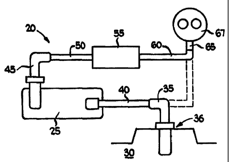
Fig. 1 is a schematic illustration of the apparatus 20 for the
treatment of gases in a positive crankcase ventilation system, according
to a preferred embodiment of the invention. Apparatus 20 is configured
to be retrofitted into existing internal combustion engine systems,
although it may be suitably modified for inclusion as original equipment,
without departing from the scope of the present invention. Apparatus 20
includes emission control device 25, connected to engine 30 by hose
adapter 35 and hose 40. Hose adapter 35 is configured to be insertingly
received into the engine 30 at the original PCV valve location 36. The
original PCV valve 45 for engine 30 is connected, by a suitably sized
hose, for example, to the outlet of emission control device 25 and by
hose 50 to electronic device 55, which is an electronic ionizer, through
which the "cleaned" gases are passed. Electronic device 55 is, in turn,
connected by hose 60 to the PCV vacuum port 65 at the intake
manifold/carburetor 67 of the internal combustion engine. In the absence
of the system of the present invention, the conventional route of the
CA 02310237 2000-OS-12
wo ~nsms PCTIUS98/02342
crankcase emissions materials is directly from. the PCV port on the
engine, to the vacuum port, as indicated by the broken line in Fig. 1.
Figs. 2 - 14A, 14B illustrate the emissions control device 25.
Reservoir 70 and lid 75 form a tank for holding a liquid filtering medium.
5 Cylindrical inlet 80 and outlet 85 are formed in lid 75. Inlet fitting 90 is
preferably threadably received in inlet 80, while outlet fitting 95 is
preferably threadably received in outlet 85. Baffle plate 100, which has
a gasket member 105 affixed to its peripheral edge, is insertably and
frictionally received in lid 75. It is important that gasket member 105
10 make a substantially air- and liquid-tight seat between lid 75 and baffle
plate 100, in order to facilitate the drawing of crankcase emissions
materials through the device 25 and on through the remainder of the
treatment system. In addition, the seal is needed to help prevent toss of
the filtering solution through spillage and seeping which might be
15 prompted, for example, by vibration of the engine. Preferably, gasket 105
is fabricated from a fluoropolymer with a hardness of 40 - 50 on a
durometer test. Fastener rod 110 is preferably threadably or otherwise
fixedly received at its lower end in a boss 115 in reservoir 70. The upper
end of fastener rod 110 passes through aligned holes in baffle plate 100
20 and lid 75, and is threaded, to receive a fastener, such as wing nut 120.
In order to ensure that a suitably tight seal is created, the wing nut 120
may be tightened snugly by hand.
Preferably, reservoir 70, lid 75, and baffle plate 100 are aff
fabricated from a durable plastic material, which will be capable of
CA 02310237 2000-OS-12
WO 99/259'12 PCTIUS98I02342
21
withstanding the heat and vibration associated with a car engine
compartment environment. In addition, the material from which reservoir
70, lid 75, and baffle plate 100 are fabricated should be capable of
resisting attack by the crankcase emissions materials which will be
passed through it, as well as attack by the chemicals in the solution
which will be stored in it, as described in further detail herein.
Figs. 5 - 7 illustrate reservoir 25 in further detail. In a preferred
embodiment of the invention, reservoir 70 is fabricated from a
substantially opaque material. A window 71, shown in broken lines, may
be provided to permit visual inspection of the level of liquid solution in
the emissions control device 25. Alternatively, reservoir 70 may be
fabricated from a transparent or translucent material, to enable visual
inspection of the liquid solution to be contained therein. Regardless of its
configuration, the reservoir should be resistant to chemical or physical
deterioration in its given environment.
The structure of lid 75 and baffle plate 100 is configured to force
crankcase emissions materials, received through inlet 90, through the
liquid solution held in emissions control device 25. Reservoir 70
preferably will be filled with a liquid solution to a level range
substantially
flush with the lower end of the open tubular boss 130 in baffle plate
100. The inside surface of reservoir 70 may carry indicia corresponding
to the numerical value of the volume of liquid solution in the reservoir. If
reservoir 70 should happen to be fabricated from transparent or
CA 02310237 2000-OS-12
WO 99125972 PCT/US98/OZ342
22
translucent material, or have a transparent or translucent window, indicia
may placed on the outside surface of the reservoir.
Figs. 8 - 10 illustrate the lid 75, which includes inlet 80 and outlet
85. Preferably, a polymer filter may be insertably received within outlet
85. Alternatively, an atomizer disc may be provided on the lower end of
outlet 85, to prevent the mass passage of liquid solution out through the
outlet 85, which might otherwise occur as a result of the suction placed
on the emissions control device 25 by the vacuum from the vacuum port.
Figs. 11 - 13 illustrate the baffle plate 100. Baffle plate 100, which
is shown upside down in Figs. 11 and 12, includes peripheral edge 125,
inlet boss 130 and intermediate boss 135. Inlet boss 130 insertably
receives interior inlet tube 140 4Fig. 14A), which preferably is also
configured from a plastic or similar material. Intermediate boss 135 is
preferably configured to receive a polymer filter for precluding passage
of liquid solution or large droplets thereof, and to restrict passage of mist
or vapor. Alternatively, an atomizer disc may be positioned at an end of
intermediate boss 135.
In a preferred embodiment of the invention, in order to further
ensure that the flow of gases is properly directed and that there are no
leaks, in addition to the gasket 105, an elastomeric grommet 106 is
provided, in the aperture 107 in baffle plate 100. Grommet 106 is
toroidal, so that fastener rod 10 passes through grommet 106.
When the emissions control device is installed to an internal
combustion engine, it is important that the emissions control device be
CA 02310237 2000-OS-12
WO 99/25972 PGT/US98/OZ342
23
installed between the crankcase of the engine and the PCV valve.
Relocation of the PCV valve downstream of the emissions control device
prevents rapid or uncontrolled evacuation or loss of the solution that may
be present in the tank for holding a liquid filtering medium, due to
increased vacuum. In addition, retaining the PCV valve prevents
increased reduction of the boiling point of the solution due to the less
relative loss of pressure (higher vacuum) controlled by the PCV valve.
Other physical characteristics of the solution and PCV pollutants, such
as vapor pressure and condensation may also be affected by higher
relative vacuum. By locating the reservoir upstream of the PCV valve,
vacuum is limited to that controlled by the original equipment valve.
A universal type plastic connector will be used for installation of
the emissions control device 25 in the original PCV location. The
connector may be of a hose barb type (similar to the connection ends of
the inlet and outlet fittings shown in Fig. 3) to allow automotive tubing
or hose to be attached to provide the gaseous connection required
between the original PCV location and the emissions control device. The
inlet fitting 90 to the emissions control device 25 is also a hose barb type
connection, preferably a right angle, that allows automotive hose to be
used for gaseous communication of crankcase emissions with the device
25. This hose barb connection is screwed into the lid 75. The inlet fitting
90 and lid 75 are in communication with interior inlet tube 140, which
provides a number of functions for the device 25.
The functions of interior inlet tube 140 include:
CA 02310237 2000-OS-12
WO 99125972 PGT/US98J02342
24
1 ) provision of gaseous communication of crankcase
emissions with the solution to be contained in device 25
and other materials which may be placed within the device
25;
2) provision of pressure relief and gas by-pass to
control aeration of the solution in the device 25, to control
solution loss and eliminate any hydraulic back pressure to
the crankcase during engine start-up and operation;
3) provision of fail safe forward motion of crankcase
emissions in case of freezing or other blockage in the device
25 due to poor maintenance, neglect or damage;
4) provision of back-flow prevention to eliminate the
possibility of the solution, etc. to be drawn back into the
crankcase due to dieseling, back-fire or other condition that
could cause a reversal of gas flow.
The interior inlet tube 140 is located toward one end of the interior
of device 25. This allows the solution to mix in a circular motion during
the aeration process. This also allows fluid movement over catalytic
materials which may be located in the device 25, and also provides
continuous mixing of the solution with crankcase emissions.
Crankcase emissions materials are diverted 90° from the direction
of travel at the elbow of the inlet fitting 90. This provides the first
inertial
break for particulate matter and/or oil/fuel droplets traveling in the gas
hose. These materials will hit the elbow wall causing rapid deceleration
CA 02310237 2000-OS-12
_ wo ~ns~rz rcTmsz
of the solidhiquid material. Crankcase emissions materials will then travel
downward into the interior inlet tube 140 which extends below the level
of the liquid solution, to a position near the bottom of the device 25, The
solid and liquid material contained in the crankcase emissions materials
5 then hit the liquid and the bottom of the device in a direction 180°
from
the outlet of the device 25 and become trapped in the device 25.
The interior inlet tube 140 is vented ( 141 ) into the device 25 near
the top tangent to the vertical flow direction. This vent is located above
the solution level and baffle plate 100 to provide the pressure relief,
10 aeration control and back-flow prevention described above. That is, if the
solution were to freeze, the suction from the intake of the engine would
still be able to pull some of the crankcase gases through the apparatus,
bypassing the frozen solution. in addition, since it is known that the
direction of the vacuum can, during the engine cycle, reverse (although
15 the magnitude of the reversed suction is not as great as the magnitude
of the normal suction flow) the vent 141 prevents the crankcase from
exerting sufficient suction to draw gases and/or filtering solution into the
crankcase.
The preferred horizontal gas flow through the vent is 360° from
20 the flow direction in the PCV hose or 180° from the elbow particle
impact area. This vent is sized to maximize gaseous communication of
the reservoir solution without physical loss of the solution downstream.
The interior inlet tube 140 further contains openings 142 at the bottom
of the tube to provide direct crankcase gas, vapor, particle, etc., contact
CA 02310237 2000-OS-12
wo ~r~smz rcrnrs9snoz~z
28
with the solution. The number and size of the openings may vary and are
may be distributed around the tube. Radialiy directed openings may also
be provided near the bottom of tube 140, and may also be provided at
several levels above the bottom of the tube. The interior of the end of
tube 140 may be conical (such as may be formed by machining the
interior opening of tube 140 from a solid piece of material. Alternatively,
the interior of the end of the tube (e.g., tube 140') may be substantially
flat, as seen in Fig. 14B.
The preferred solution to be used in device 25 will comprise a
mixture of uninhibited food grade or USP grade 1,2-dihydroxypropane
and water. The dihydroxypropane (propylene glycol) is a type of anti-
freeze. The freeze point of this material is on the order of -78°F,
depending upon the mixture to provide freeze protection in cold climates.
A trace amount of methyl, ethyl, isopropyl, butyl or other alcohol may be
added to the solution to improve the solubility of the fuel, oil, sludge and
vapors with the solution. Ethyl and isopropyl are preferred due to the
solubility of these alcohols with gasoline and water. Ethyl alcohol is used
to make gasohol blended gasoline fuel. Isopropyl alcohol is used in gas
line antifreeze and will not cloud, tike methanol.
Uninhibited food or USP grade propylene glycol is used due to low
toxicity, environmental compatibility (before mixing with oil; sludge and
other contaminants) and lack of dye, color and antioxidants. The USP
grade is preferred due to reagent purity.
CA 02310237 2000-OS-12
wo ~r~sgn pcrnrsssroz34z
27
The water mixed with the glycol will be purified water with a
minimum specific resistance of 100,00 ohm-centimeter at 25°C for the
system of the present invention. Purified water at 100,000 ohm-
centimeter is consistent with water having less than 5.0 ppm total
ionized solids. This water may be prepared by reverse osmosis,
distillation, deionization or a combination of all three methods, and should
contain less than 10.0 ppm silica as Si03. Water with an ionic content
greater than 5.0 ppm may interfere with the electronic ionizer located
downstream of the chamber, particularly if divalent cations are present
in the water.
The mixing action of the fuel, oil, sludge, etc., and glycol is based
on the chemical principle that like materials dissolve like materials. For
example, motor oil is soluble in gasoline, gasoline is soluble in alcohol
and glycol, and alcohol and glycol are soluble in water. The results of
mixing the above-listed components is an emulsion of oily fuel,
glycol/alcohol and water. This emulsion contains a large amount of
minute oily droplets of oily fuel that remain separated into small droplets
even after aeration or agitation has stopped. This effect is similar to that
caused by the use of soap or detergent on such materials, but does not
produce foam or lather in the process. The creation of the emulsion
results in an exponential increase in the surface area contact between the
oily fuel and glycol that greatly increases the oxidation potential
~breakdown) of the oil. The fractions that completely mix will have a
reduced flash point. Any fraction that does not completely dissolve will
CA 02310237 2000-OS-12
wo ~nsmZ rcrnJS~oz3aZ
28
also burn easier due to the size of the suspended_ particles (droplets) and
the fact that the undissolved fractions are surrounded by more flammable
material. Glycol vapors and mist are combustible. Oily fuel and glycol
vapors/mist mixed together are also combustible. The water present
serves to retard the system and, in combination with the glycol, helps to
limit evaporation. All of the foregoing materials in the solution are
environmentally safe and non-toxic, prior to contact with the engine
emissions.
During operation of the device 25, the oily fuel droplets are
atomized as an aerosol with the glycol/water vapors. This provides a
vapor or mist from the device 25 that has a substantially reduced flash
point as compared to direct oillgasoline mixtures, particles and sludge
from a standard PCV system. in other words, by dispersing the heavy
oils and gasoline into the solution and dissolving some of the
hydrocarbon and gases into the solution, combustion is easier to achieve
by passive control. The fumes, vapors and mist exiting the device 25
have a lower and more consistent flash point range. Without the device
25, the concentrations of oil and gasoline reaching the combustion
chamber are substantially uncontrollable. Heavy high flash point oils may
reach the combustion chamber intermittently with lower flash point fuel
and gases, which may interrupt even combustion.
The glycol contains 42°36 oxygen by weight. Ethyl alcohol contains
350 oxygen by weight. Carbon monoxide and carbon dioxide will be
absorbed into the solution at a rate that is equivalent to the partial
CA 02310237 2000-OS-12
wo ~nsmz rcTws~sro~2
29
pressure for each compound. This absorption will be limited by the
pressure or lack of pressure available within device 25. Carbon dioxide
disassociates in water solutions to form carbonic acid. This further
increases the amount of oxygen in the solution. Nitrous oxides are
sparingly soluble in water and alcohols. However, oxides of nitrogen will
support combustion via the oxygen content of the compound. By
increasing the amount of available oxygen in the solution, the potential
for efficient combustion is increased. Furthermore, by maintaining a
higher level of oxygen for combustion, to a point, further production of
oxides of nitrogen are limited. Oxidation of 'the hydrocarbons (oily fuel)
in the gases will also begin in the solution prior to combustion.
Reagent grade hydrogen peroxide, ACS grade of variable strength,
but no greater a strength or concentration than about 8°r6 by weight,
may also be added to the solution as part or all of the water fraction. 3%
by weight is preferred. Peroxide added to the solution will provide a
strong oxidizing agent that will assist in the breakdown of organic
compounds in the solution. Peroxide in greater strength will decompose
the glycol and other organic material too quickly. The peroxide will also
increase the oxygen content in the solution.
A preferred formulation of the liquid filtering solution could be as
follows:
37°yo by volume water (deionized and purified as described
hereinabove),
55% by volume propylene glycol,
CA 02310237 2000-OS-12
wo ~nsmz p~'rn~sz
5°J~6 by volume ethyl and/or isopropyl alcohol, and
3% by volume hydrogen peroxide solution (3°~6 by wt.), although
the constituencies and proportions of the liquid filtering solution may be
varied as required by the particular application and/or availability of
5 materials.
Catalytic materials may also be placed in the solution to assist with
the breakdown of crankcase organic materials. These catalytic materials
may include dissimilar metals that will create a galvanic cell when
exposed to water. The galvanic cell function (corrosion) will generate
10 hydroxyl free radicals in the solution. In doing so, depending on the types
of metals used, multivalent metal cations may also be released into the
solution. In too high a quantity, the multivalent cations may interfere with
the ionization electrodes downstream. Therefore, the dissimilar metals
used for the galvanic cell should be relatively close together in the
15 galvanic series to limit the rate of corrosion.
An example of dissimilar metals in this solution that would be less
desirable, though functional, would be copper and aluminum. An example
that would be more desirable would be a zinc-copper pairing. The
preferred materials) would consist of dissimilar metals that are located
20 closer together in the galvanic series. This would create a much lower
and slower oxidation/reduction potential in the device 25 and provide
better control of the system. Aluminum and copper are quite far apart in
the galvanic series and under certain conditions may self-destruct rapidly.
CA 02310237 2000-OS-12
WO 991259'12 PCT/US98/OZ342
31
Metals such as tin and naval brass would provide a suitable, less active,
galvanic cell.
There are metal alloys available, such as KDF 55 Process Medium
and KDF wool that will provide the oxidation/reduction potential required
to assist in the~breakdown of organic crankcase emissions materials. This
material is made of zinc and copper in ratios that provide efficient
oxidationlreduction potential when contacted with water. This material
is typically used in water purification, and the mechanisms for breaking
down organic materials in the crankcase emissions materials are similar.
Strontium and barium ferrite, magnetic or non-magnetic, will also produce
hydroxyl radicals in solution.
The purpose of the catalytic materials is to produce hydroxyl free
radicals (OH-1 in solution. Hydroxyl radicals are efficient at breaking down
organic compounds in aqueous solutions. The ability of hydroxyl free
radicals to destroy organic compounds is known. The ultimate
byproducts of the destruction of light organic materials by hydroxyl free
radicals are carbon dioxide and water. However, the heavy oils which
may be present in crankcase emissions materials will be broken down
into smaller, lower flash point molecular weight compounds during the
oxidationlreduction process. This will produce lower molecular weight
intermediate organic compounds in the reservoir, which have lower flash
points. Even when the engine is shut off, these chemical reactions will
continue to take place in device 25.
CA 02310237 2000-OS-12
wo ~rzs~ rcrrt~sz
32
As a practical matter, because the crankcase gas velocities are
high, and the residence time in the device 25 is short, complete
breakdownlconversion of the organic materials in the crankcase
emissions materials by device 25 is a practical impossibility, for any
device sized to be usable in a consumer vehicle. However, using
commercially justifiable materials, device 25 can and will provide marked
improvement in the quality of the crankcase emissions materials.
Materials to be used for the solution should be chosen to provide
suitable gas treatment characteristics, but still be reasonable economical.
For example, the propylene glycol based antifreeze sold under the brand
name SIERRA~ could be used as a solution base. Pieces of copper, brass
or bronze metal could be used as catalytic materials. Copper oxides
formed by any copper containing materials can be used to assist in the
destruction of oxides of nitrogen. Gold and platinum materials can be
used, if economically justified.
Once the crankcase emissions have entered the device 25 and
solution, essentially ail the heavy hydrocarbon and particulate matter will
be trapped in the device 25. Thus, only the lighter hydrocarbons and
gases will be able to escape device 25 to proceed to the intake manifold.
The lighter hydrocarbons should consist mainly of a lower flash point
mixture of hydrocarbon vapor, mists and gases. This provides control of
the crankcase emissions at a level more suitable for combustion, thus
reducing emissions and increasing fuel economy.
CA 02310237 2000-OS-12
WO 99/Z5972 PCTIUS9~02342
33
The baffle plate 100 in device 25 ensures prevention of direct
aspiration of the solution, when the vehicle travels on rough surfaces, or
steep or tilted surfaces. In the event that the solution is splashed against
the underside of baffle plate 100, a filtration device will be located in
intermediate boss 135, having preferably a 225 micron nominal pore size
may be provided. This will prevent particles from passing above the
baffle plate. Liquid that passes above the baffle plate will be prompted
to drain back into the reservoir. The angles and elevation of the baffle
plate filter will tend to prevent direct aspiration of solution into the
outlet
fitting 95 of device 25. Outlet 85 of lid 75 may also be provided with a
filtration device having preferably a 225 micron nominal pore size may be
provided. Any liquid reaching this location will be atomized into small
droplets when subjected to the velocity of the exit gases from device 25.
A preferred filter device may be obtained from Porex Industries,
and is fabricated from polypropylene. Alternatively, a metal screen having
a substantially similar nominal pore size, may be used.
Figs. 15 - 16 illustrate an emissions control device 25' according
to an alternative embodiment of the invention, wherein elements having
simiiar structure and function to those of the embodiment of Figs. 2 -
14A, 14B are provided with like reference numerals, augmented by
primes ('). Device 25' is provided with a substantially flat baffle plate
100', with a large aperture 130' for receiving interior inlet tube 140', and
a plurality of smaller intermediate apertures 135'. Interior inlet tube 140'
CA 02310237 2000-OS-12
wo ~ns~n ~TN52
34
has a stepped configuration at its lower end, with apertures 142'
extending in both axial and radial directions.
As the vehicle is operated, there will be some attrition of the
solution level in device 25, over time, as a result of evaporation, and/or
chemical reaction. Solution may be added as needed to maintain the level
determined to be appropriate for the device, as sized to. the particular
engine. However, a complete change-out of the solution, and a cleaning
of the interior surfaces of the device, will be necessary from time to time,
in order to remove oily residue and particulate materials from the
reservoir. Preferably, device 25 should be sized, so that under normal
operating conditions and assuming normal usage, the solution should be
completely changed approximately as often as the crankcase oil itself is
changed, e.g., every three months or three thousand miles driven.
In addition to the physical and chemical treatment of crankcase
emissions materials which is performed by device 25 (25'), it has been
determined that treatment of the "cleaned" gases leaving the device 25
(25') by electronic ionization also has beneficial effects. Accordingly, in
addition to the device 25, the apparatus for the treatment of crankcase
emissions materials may also include a device for the electronic treatment
of crankcase emissions materials. Figs. 17 - 21 illustrate an ionizer
apparatus used in association with the present invention.
lonizer 55 comprises base 155, with maze walls 160 and 165, and
diagonal wall 167, on the inlet side of ionizer 55. The inner surfaces of
the peripheral walls of base 155 may be provided with ledges 170, upon
CA 02310237 2000-OS-12
wo ~nsmz rc~'n~s2
which intermediate wall 175 may rest. Intermediate wall 175 may also
rest atop the upper ends of wails 160, 165, 187 to form charging
chamber maze 178. Intermediate wall 175 has a plurality of apertures
180, through which ion emitter pins 185 project, into charging chamber
5 maze 178, between walls 160 and 165. Emitter pins 185 project from
circuit board 190, which is covered by cover 195. Base 155 includes
inlet fitting 200 and outlet fitting 205, which connect with corresponding
apertures in the walls of base 155. Maze walls 160 and 165 have
apertures 210 and 215, respectively, for permitting passage of gases
10 through maze 178. When the components of ionizer 55 are assembled,
preferably with at least base 155 and cover 195 being fabricated from a
durable plastic material and which can be sealing affixed to one another,
an air-tight passage is formed. It is believed that the construction of maze
walls 160, 165, and diagonal wall 167, induce a swirling action to the
15 flow of "cleaned" crankcase gases through the ionizer, optimizing the
charging of the gases, vapors, etc, passing through the ionizer. Although
a particular maze configuration is shown herein, the configuration may
be modified, in accordance with the requirements of a particular
application, and not depart from the principles of the present invention,
20 if a swirling motion is produced.
The components of circuit board 190 preferably comprise a direct
current to alternating current converter 220, the function of which is to
change DC voltage, available in an automotive application, to AC voltage,
to be amplified through transformer 225, with a suitable voltage
CA 02310237 2000-OS-12
WO 99IZ5972 YCT/US98/02342
38
amplification factor to provide voltage and current to mufti-stage,
capacitive coupled, series connected diode array voltage multiplier 230,
arranged to provide an optimum particle charge to emitter pins 185.
Emitter pins 185, as stated earlier, project into charge chamber maze
178. Crankcase emissions materials flowing through maze 178 are
forced, by the contoured surfaces, to swirl and counter-swirl, prompting
maximum contact with the emitter pins 185. Maximum contact prompts
maximum charging of the gas and gaseous particles. Thus an optimum
quantity of charged particles will be generated for transport to the intake
air stream.
Careful consideration of component parts must be made in order
to avoid degradation of and/or interference with engine control onboard
computer or other electronic device used in or about the vehicle. Proper
shielding, feedback protection and isolation are important. It is believed
that frequencies of 15 - 20 kHz are appropriate and should present no
significant difficulties with respect to interference issues, although other
frequencies may be used, as desired andlor other characteristics of the
vehicle or other apparatus, into which the invention is to be installed,
dictate.
It . is believed that voltages for generating a significant suitably
charged field can be as low as 600v. Voltages in the range of 1200 -
8000v are believed to be optimal for achieving the desired performance,
although any ionizing voltage will have some effect.
CA 02310237 2000-OS-12
WO 99/Z597Z PCTIUS98/0234Z
37
Figs. 21 illustrates a possible circuit schematic for the oscillator
circuitry for the ionizer. Although desired numerical values for various
components have been provided, one of ordinary skill in the art, having
the present disclosure before them, will be able to modify these circuits
and vary the numerical values, to produce suitable ionizer apparatus,
without departing from the scope of the invention. In addition, the
particular configuration and placement of the electrical connections may
be modified without departing from the scope of the invention.
The electronic device 55 of the present invention may be used in
conjunction with the liquid treatment device 25, in a position
downstream from device 25. Alternatively, electronic device 55 may be
used by itself in the flow path from the PCV valve to the intake vacuum
port, although cleaning of the electronic device 55 to remove
oily/particulate deposits will be required more often than if device 55
were used in association with liquid treatment device 25.
Unlike prior art devices, which may have incorporated both liquid
filtering and electronic ionization apparatus, within a single bulky
housing, the present invention separates these two functions, into two
separate units. This enables the ionizer to be positioned downstream of
the liquid filtering unit, and downstream of the PCV valve itself, as well.
In addition, the construction of the present invention permits the ionizer
unit to be positioned as closely to the intake manifold/throttie body, as
physical space limitations and the heat of the engine permit. In this way,
the volume and strength of the field of charged particles is increased.
CA 02310237 2000-OS-12
wo ~nsmz rcrms9z
38
The farther the ionizer is positioned from the intake manifold, etc., the
more likelihood there is that the charged gases and gaseous particles will
lose their charge. Ideally, a linear distance of approximately 1 foot
upstream from the intake manifold, if feasible, is desired.
Some of the advantages believed to result from the ionization of
the gases is that the combustible elements of the crankcase emissions
materials are prompted to be more easily combusted, and that a
"cleaning" action is induced in the combustion system, prompting cleaner
burning and the expulsion or removal of hydrocarbon deposits and
inhibition of corrosion.
The present invention also comprises a mounting system
configured for the mounting of the emissions control device, as illustrated
in Figs. 2, 3, 22 - 32. The mounting system comprises a first flat bracket
240 that mounts to tid 70 and is able to adjust fore and aft about the "z"
axis via a plurality of mounting holes 245 and is also able to adjust
angularly about the horizontal "x" axis by rotating the bracket about the
selected mounting hole. A second angled bracket 250 is attached to the
flat bracket 240 with _ a screw 257 that passes through apertures 241
and 242 in tabs 243, 244 of bracket 240, and through one of apertures
251, 252 on tabs 253, 254, respectively, of bracket 250. Brackets 240,
250 may be fabricated from any suitable material, such as metal or
durable plastic. The connection acts as a hinge and is able to adjust
angularly about the vertical "y" axis. A toothed lock washer 256, such
as are known in the fastener act, is placed at one end of screw 257, to
CA 02310237 2000-OS-12
wo ~r~s~rZ rc~rrt~saz
39
be in compression between one of tabs 253, 254, and one of tabs 242,
243 to provide a gripping force, once screw 257 has been tightened
down, to help hold bracket 240 in the selected angular position relative
to bracket 250. In the embodiment as illustrated in Fig. 29, the end of
screw 257 is threaded, and the interior of aperture 241 is likewise
matingly threaded, to engage with the end of screw 257.
One of tabs 253, 254 can be selected that will allow for mounting
either in a horizontal or vertical position relative to bracket 240. In
particular, each of tabs 253, 254 permits positioning of bracket 240, in
a range of angular positions, relative to bracket 250. The range of
positions available when tab 253 is used, centers around a position
which is substantially perpendicular to the position around which the
range of positions centers, when tab 254 is used. The design allows for
adjustments in the "x", "y" and "z" axes and gives maximum versatility
thereby allowing for the device 25 to be mounted in many different
engine compartment configurations in many different vehicles.
Bracket 250 is also provided with two apertures 258, which are
configured to enable attachment of bracket 250 to a structure within the
engine compartment, by bolts or metal screws, for example.
Figures 30 - 32 illustrate three potential orientations of brackets
240 and 250, which can be obtained.
A typical installation procedure for the apparatus of the present
invention is as follows.
CA 02310237 2000-OS-12
wo ~nsmz rc~'n~sz
1. Locate and remove original PCV valve and
hose.
2. Mount the device 25 in a suitable location,
allowing access to the inlet and outlet fittings.
5 3. Install the hose adapter in the original PCV
grommet.
4. Route a section of new PCV hose from the
previously installed hose adapter to the device inlet fitting
using suitable fittings and clamps. The device 25 should be
10 mounted so that the inlet and outlet fittings are
substantially upright and on top.
5. Install the proper size outlet fitting into the
device 25 outlet port, connect a short length of either 1 /2"
or 3/4" ID hose, to match the PCV valve OD, to the outlet
15 elbow then install the original PCV valve into the hose,
route a new PCV hose from the PCV valve to the PCV port
at the intake manifold. Locate a suitable location for the
electronic assembly and install it in the PCV hose between
the PCV valve and the engine. Use nylon tie straps to
20 secure hoses and wires for a neat installation. Clamp all
hose connections.
fi. Remove the top section of the device 25 by
removing the wing nut and fill to the operating level with
the solution as selected.
CA 02310237 2000-OS-12
wo ~nsmz pc~rms9sio~az
41
7. Connect the negative/black lead from the
ionizer unit 55 to a good vehicle ground, connect the
positive/red lead to a circuit that has + 12vDC with the
ignition key in the run position.
8. Check hose routing for interference, start
engine and run for 30 seconds, stop the engine and check
for leaks.
The apparatus of the present invention is believed to improve
emissions by reducing the production of unburned or incompletely burned
hydrocarbons, carbon monoxide and oxides of nitrogen. Improvement in
fuel efficiency is also believed to result.
The foregoing description and drawings merely explain and
illustrate the invention, and the invention is not limited thereto except
insofar as the appended claims are so limited, as those skilled in the art
who have the disclosure before them will be able to make modifications
and variations therein without departing from the scope of the invention.