Note: Descriptions are shown in the official language in which they were submitted.
CA 02310245 2000-OS-12
WO 99/25546 PCT/US98/Z4066
-1- _
GUIDE MECHANISM FOR A PACKAGING MACHINE
Background of the Invention
This invention relates to packaging cartons and is more particularly concerned
with
feeding such cartons in collapsed condition from a hopper and for initiating
and
then completing a set up operation of cartons in sequence.
US 4 881 934 illustrates a rotary transfer mechanism which has a carrier
means rotatable with a drive shaft on a support member. A support shaft is
provided which is rotatable on the carrier means and includes a suction cup
for
receiving a carton which is caused to follow a path and thereafter, to be
placed on
a conveyor. Fixed guide rails provided adjacent the conveyor: the rails are
curved
in such a manner to permit placement of the carton on the lug conveyor and
hold
the carton in position on the conveyor.
A problem associated with using fixed guides is that they are required to be
positioned to avoid the path of the feeder mechanism as the carton is being
placed
onto the conveyor. Furthermore, the use of fixed guides is undesirable when a
force is required to be applied to the carton to guide it to a preferred
position on
the conveyor.
An alternative approach to supporting the carton during carton set up is
illustrated in US 5 102 385. This document shows a feeder mechanism for
setting
up cartons including a rotating suction cup which is moveable inwardly and
outwardly on a slidable rod. The suction cup mechanism includes a leaf spring
clip
to engage and hold a carton down following deposit thereof on a conveyor.
Thus,
the feeder mechanism is required to have leaf spring clips attached to each
suction
cup assembly which increases the complexity of the mechanism which is
undesirable.
CA 02310245 2000-OS-12
WO 99/25546 PCT/US98/24066
-2-
In order to increase the packaging speeds of equipment, it is preferred to
position the cartons on a conveyor as quickly as possible so that conveying
speeds
are improved. A further problem associated with known feeder mechanisms is
that
the shape of the carton in its set up form may have an undesirable impact on
packaging speeds. For example, a pizza box usually comprises large top and
bottom panels and relatively narrow side panels. If a carton of this shape is
fed
onto a conveyor by using suction cup means known in the art, then the
relatively
large surface area of the box results in a carton which is difficult to
control. Thus,
the positioning of such a carton onto a conveyor by known means makes the
alignment of a carton between lugs difficult: one result being that packaging
speeds may need to be reduced.
Summary of the Invention
The present invention seeks to overcome or at least mitigate the problems
outlined above and associated with the prior art. It is envisaged that the
present
invention can be used with various other types of packaging machine.
Alternatively,
the erecting mechanism of the present invention can be sold as an individual
module
to be fitted to new equipment or to existing equipment on a retro fit basis.
One aspect of the invention provides an apparatus for manipulating out of a
hopper sequential collapsed sleeve type end loading cartons having oppositely
disposed
face contacting panels and for initiating set up thereof into open ended
condition, the
apparatus comprising a rotatable shaft, carton pick up means for sequentially
engaging
one of said face contacting panels and for withdrawing from the hopper the
collapsed
carton which includes one of the face contacting panels, a rotatable elongate
support
rod having one end thereof secured to said shaft and on the other end of which
said
carton pick up means is disposed, wherein said carton pick means is arranged
to
deposit a set up carton on a conveyor characterised in that oscillatable guide
means is
disposed outside the path of orbital movement of said carton pick up means to
engage
and hold said carton down following or during deposit thereof on said
conveyor.
CA 02310245 2000-OS-12
WO 99/25546 PCT/US98/24066
-3- _
According to an optional feature of this aspect of the invention, the
oscillatable
guide means may be oscillated by driving means interconnected with said
oscillatable
means by a driving link.
According to another optional feature of this aspect of the invention, the
oscillating guide means may comprise an oscillatable arm moveable in a plane
substantially parallel to said conveyor wherein said oscillatable arm includes
a guide
surface to guide said carton into a position between leading and trailing lugs
mounted
on the conveyor. Preferably, the guide surface is moveable in a path
interrupting the
path of orbital movement of said carton pick up means.
Another aspect of the invention provides a device in a packaging machine for
aligning a carton to a position between leading and trailing lugs on a
conveyor which
device comprises an oscillatable arm disposed above the conveyor and including
a first
guide surface to guide the carton into said position, wherein the first guide
surface is
moveable in a plane substantially parallel to said conveyor.
According to an optional feature of either aspect of the invention, the
oscillating arm may include a second guide surface adjacent the first guide
surface,
wherein the first guide surface applies a force to said carton to guide said
carton into
said position, and thereafter the second guide surface applies a second force
to
accurately align said carton in the position. Preferably, the second force may
be
greater than the force applied by the first guide surface.
Brief Description of the Drawings
An embodiment of the invention will now be described, by way of example,
with reference to the accompanying drawings in which:
FIGURE 1 is a perspective view of a carton suitable for use with the machine
according to the invention;
CA 02310245 2000-OS-12
WO 99/25546 PC"T/US98/24066
-4- _
FIGURE 2 is a perspective view of the infeed of a packaging machine
illustrating the feed mechanism and oscillating guide means of this invention;
and
FIGURES 3 to 8 are perspective views and side profiles of the infeed end of
the machine illustrating the erection of a carton in accordance with a
preferred
embodiment of the invention.
Detailed Description of the Preferred Embodiment
A mechanism according to an aspect of the present invention is capable of
storing and feeding a variety of carton types, for example wraparound or fully
enclosed cartons. Any reference in this specification to carton type includes
different
sizes of any particular carton style.
Referring to the drawings, one example of the carton 10 to be used in
conjunction with a mechanism of the preferred embodiment is shown in Figure 1
in
a set up condition ready for receiving foodstuff, for example a pizza. The
carton 10
is formed from a unitary blank of paperboard or other foldable sheet material
and
includes opposed side wall panels 12,14 and opposed end wall panels 16, 18
hingeably
connected one to next. The carton further comprises top panel 20 and base
panel 22
hingeably connected to opposed edges of side walls 12, 14. An article, for
example
a pizza, can be inserted into the carton from one side and the end panels 16,
18 are
then secured together to provide a fully enclosed carton.
It is envisaged that the cartons will vary depending upon the shape and or
quantity of articles to be packaged and accordingly, a machine in accordance
with the
CA 02310245 2000-OS-12
WO 99/25546 _ PCT/US98/24066
-5- _
present invention is adjustable in numerous respects so that it can process a
wide
variety of such cartons, for example sleeve type cartons used in the bottling
industry.
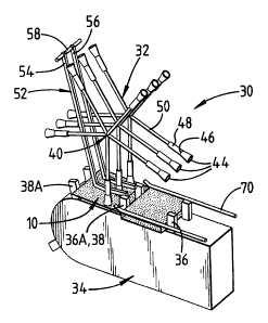
Referring now to Figure 2 of the drawings, there is shown a machine 30 for
processing cartons of the type outlined above. The upstream end of the machine
includes a hopper (not shown) or other suitable means for storing the carton
in which
a multiplicity of cartons 10 in a collapsed condition are held ready for
processing.
Preferably, a rotary vacuum feeder 32 is positioned adjacent the hopper. In
this
embodiment, a paper feed chain 34 (or conveyor) is provided to transfer
cartons
downstream to a loading station (not shown). The conveyor 34 includes leading
and
trailing lugs 36, 38, 36A, 38A, well known in the art, which engage the
cartons as
they are moved downstream.
The feeder mechanism 32 includes a main shaft 40 rotatable about a fixed axis.
The shaft 40 is generally supported at its end by a suitable bearing structure
but which
is conventional and which is mounted to a side frame. Suitable driving
mechanism,
for example a servo motor is provided to rotate the shaft 40.
For withdrawing the lower most collapsed carton from the first hopper, a
carton pick up means 42 is provided, including three suction cups 44 which are
each
supported on cup holders 46 and a frame 48. The cup holder frames 48 are
fixedly
mounted respectively on elongate support rods 50. In one class of embodiments,
the
rods 50 are slidably mounted respectively on a collar structure (not shown),
which
collar structure is rigidly secured to the main rotatable shaft 40. The frames
48 may
be mounted onto cam rods (not shown) extending into the side frame housing a
cam
track (not shown). The purpose of the cam track would be to facilitate the cam
rods
to be extended away from the main shaft 40 so that the suction cups 44 would
come
into contact with the carton 10 thereby to remove one of the cartons from the
hopper
and to rotate the carton in a uniform path to the paper feed chain 34.
CA 02310245 2000-OS-12
WO 99~Z5546 PCT/US98/24066
-6- _
In this embodiment, it is envisaged that a vacuum break is provided in the
feeder mechanism 32 which is used in conjunction with a vacuum supply to set
the
vacuum connection and cut off points thereby determining the length of time
and/or
for the distance through which the canon is held by the feeder mechanism 32.
As
illustrated in Figures 2 and 3, five sets of carton pick up means 42 are
provided in
association with the main rotatable shaft 40. Only one set of such devices
such as
those indicated at 42 are described in detail because all five sets of pick up
means are
of the same construction and operate in an identical fashion.
As illustrated in Figures 2 and 3 4, oscillatable guide means 52 is positioned
outside the path of orbital movement of the suction cups 44. The oscillatable
guide
means 52 comprises a first arm 54 and preferably, a second arm 56 connected to
driving means, for example eccentric driving means or a servo motor, by a
driving
link 58. In this embodiment, the first arm 54 is substantially "L" shaped with
a
portion 60 being positioned adjacent to and spaced from the conveyor. Portion
60 is
provided with first and second guide surfaces 62, 64 positioned one to next in
an
angular relationship. The second arm 56 is spaced from the first arm 54 and is
of
same construction and operates in an identical fashion, so it is not described
in any
greater detail. As shown in Figure 2, each arm 54, 56 is moveable in the space
between adjacent suction cups 44.
Whilst the use of a rotary vacuum feeder to supply cartons to the conveyor is
preferred, it is envisaged that the present invention can be used or adapted
to be used
with other types of feeder mechanisms without departing from the scope of the
invention.
Further, the present invention is not limited to guiding a carton being fed
onto
a conveyor. For example, the oscillating arm can be placed at a loading
station, if it
is desired to apply a downward or positive force to the carton during loading
to
improve carton stability. Indeed, it is envisaged the invention can be used at
any
CA 02310245 2000-OS-12
WO 99/25546 PCTNS98/24066
_7_ _
position in a packaging machine where it is required to guide a carton to a
position to
apply a downward or positive force to the carton to stabilize or to re-align
it.
In use, the feeder mechanism 32 continuously and sequentially feeds cartons
from the hopper to the paper feed chain 34 by the main shaft 40 rotating the
pick up
means 42 in the direction indicated by the arrow A, shown in Figure 4. As the
pick
up means 42 rotates, the suction cups 40 are moved into contact with a top
wall of the
carton 10. A vacuum is then applied to the set of suction cups 44, by the
vacuum
supply. Thus, the carton 10 is withdrawn from the hopper and then transferred
to the
paper feed chain 34. The vacuum is maintained during this transfer stage so
that the
suction cups 44 hold the top wall 20 of the carton 10. When the carton is
deposited
at the paper feed chain 34, the vacuum break disconnects the vacuum supply
from the
suction cups 44 to release the carton. In this embodiment shown in Figures 3
and 4,
the suction cups 44 hold the carton towards its leading edge 66 to prevent
unwanted
movement as the leading edge 66 comes into contact with the leading lug 36 or
36A
hereinafter described.
The erection of the carton is now described by reference to Figures 3 to 8. In
Figure 4, the lead edge 66 of a carton is moved towards the leading lug 36A
mounted
on the conveyor 34, which is moving forward in direction "A" . The arms 54, 56
are
synchronously moved in direction "X" away from the carton, to enable the
carton to
continue on an unimpeded path towards the conveyor 34.
Figure 5 shows the next stage, where the leading edge 66 in contact with the
leading lug 36A and the arms 54, 56 in a fully retracted position. The carton
continues to move forward relative the conveyor 34 and leading lug 36A and
carton
set up is initiated by the top and bottom walls being separated by the leading
lug 36A,
by means known in the art and illustrated in Figure 6. For example, abutment
of the
loading edge 66 with the leading lug 36A, causes the top and bottom walls 20,
22 to
move apart, because the carton continues to advance relative the leading lug
36A. At
CA 02310245 2000-OS-12
WO 99/25546 PCTNS98/24066
_8_ _
this stage, the arms 54, 56 are moved in the opposite direction "Y", and the
top panel
20 comes into contact with the first guide surface 62.
As the carton continues to move forward by the feeder, the first guide surface
62, moves the carton in a downward direction "C". The arms 54, 56 continue to
move in direction "Y", and the first guide surface 62 moves out of contact
with the
carton and the second guide surface 64 becomes operative, as shown in Figure
7. The
second guide surface pushes downward on the rear end portion 68 of the carton
as the
arm 54, 56 move in direction "Y" to stabilize and/or guide the carton.
Thereafter,
the trailing lug 38A comes into contact with the rear side wall 14 of the
carton to
complete the set up of the carton. At the same time, the oscillating guide
means
continues to move in direction "Y" and aligns the rear portion of the carton
on the
conveyor as shown in Figure 8.
As the carton moves downstream on the conveyor and is held in place by the
leading and trailing lugs 36, 38, 36A, 38A and a pair of fixed guides 70 shown
in
Figure 8. The oscillating arms 54, 56 are reversed in direction and move back
to the
retracted position shown in Figure 4, so that a second carton can be received
by the
conveyor. Thus, the process of carton set up and positioning on a conveyor is
repeated, which is usually a continuous process in a packaging machine.
It is envisaged that the arms 54, 56 could include only one guide surface to
guide and/or align carton being set up without departing from the scope of the
invention.
According to this invention the speed of operation of the apparatus is
improved
as well as its efficiency and durability as the carton is moved from a
collapsed position
to a fully set up condition.
While the preferred embodiment described herein is to be used with packaging
machines for loading pizzas into cartons, it will be recognised that the
invention is not
limited to such cartons. The invention may be used with machines for packaging
cans,
CA 02310245 2000-OS-12
WO 99/25546 PCTNS98/24066
-9-
paperboard "bricks" and other containers into cartons. Moreover, while the
preferred
embodiment described herein is shown as part of a machine for loading
containers into
horizontally-loaded sleeve-type carton, the invention is not limited to
cartons of this
type.
It will be understood that the feeder and/or guide mechanism of the invention
has been illustrated with reference to a specific embodiment and that numerous
modifications are possible within the scope of the invention.