Note: Descriptions are shown in the official language in which they were submitted.
CA 02310284 2000-OS-16
WO 00/16994 1 PGTIUS99/20440
PRESSURE SEALER THREE TIERED SEALING ROLL CONFIGURATION
BACKGROUND AND SUMMARY OF THE INVENTION
Business forms with pressure activated adhesive or cohesive have become
increasingly popular because of numerous practical advantages associated
therewith.
These adhesives (such as sold by Toppan Forms Company of Japan with a trade
designation TN124, and as disclosed in U.S. patents 4,918,128, 5,190,818,
5,314,944
and 5,427,851 ) require application of a substantial force in order to effect
sealing. A
wide variety of different pieces of pressure seal equipment have been
developed for
that purpose, such as sold by Moore U.S.A., Inc. of Lake Forest, Illinois
under the
trademark "SpeediSealer", and such as shown in U.S. patents 5,169,489,
5,378,303,
5,397,427 and 5,527,416 (the disclosures of which are hereby incorporated by
reference herein). While this commercial equipment is very useful in effecting
proper
sealing and handling of business forms with pressure activated adhesive or
cohesive, it
would be desirable to reduce the weight of the equipment, reduce its foot
print, and
provide a lower cost to the end user.
According to the present invention a method of handling business forms with
pressure activated adhesive or cohesive thereon, and sealing apparatus that
can be
utilized with such business forms (or with other webs or sheets) is provided
which has a
number of advantages over conventional, methods and equipment under some
circumstances. The equipment provided according to the invention can have
reduced
weight, a reduced foot print, and a lower cost to the end user than equipment
such as
described above since the number of rollers utilized to effect the sealing
action is
reduced, and they can be positioned in such a way as to have a small foot
print.
Despite reduced weight, foot print, and cost, the equipment according to the
invention
can substantially effectively seal business forms as conventional equipment
for that
purpose.
According to one aspect of the present invention a method of handling business
forms with pressure activated adhesive or cohesive thereon using at least
first, second
and third rollers each having an axis of rotation, and the axes of rotation
being vertically
spaced from each other so that the second roller axis is at a vertical
location
intermediate the first and third roller axes, and a first nip is formed
between the first and
CA 02310284 2000-OS-16
WO 00/16994 2 PCT/US99I20440
second rollers and a second nip is formed between the second and third rollers
is
provided. The method comprises: (a) Feeding a business form with pressure
activated
adhesive or cohesive thereon into and through the first nip to effect
compression. (b)
Changing the direction of movement of the business form to direct the business
form
toward the second nip. And (c) feeding the business form into and through the
second
nip to effect sealing of the pressure activated adhesive or cohesive on that
part of the a
business form between the rollers.
Typically (c) is practiced to apply a force to the business form between the
second and third rollers of between about 100-200 lineal pounds per inch, and
{a) is
practiced to also apply the same general level of force, e.g. between about
100-200
pounds per lineal inch. (a) and (c) are also preferably practiced to operate
on two
different forms at the same time, that is one form goes through the first nip
while a
second form is passing through the second nip. This maximizes the pressure in
both
the compression and sealing phases (that is between the first and second
nips).
(b) may be practiced by feeding the business form into contact with a
substantially semicircular stationary surface, or by using a plurality of sets
of re-
directing rollers, with or without stationary guides associated with them. Any
other
conventional equipment can also be used which effectively allows re-direction
of a form
once passing through the first nip to the second nip.
The business forms may be constructed to have pressure activated cohesive or
adhesive in strips along two peripheral portions thereof, and (a) and (c) may
be
practiced (using rollers designed for that purpose) to act substantially only
on the
peripheral portions of the form. This is particularly useful when the form is
to have
inserts and it is desired not to "crush" the inserts. Alternatively, however,
especially
where inserts are not used in the form, and the form has a width substantially
transverse to the primary direction that it moves through the nips, {a) and
(c) are
practiced to act along substantially the entire width of the business form. In
such a
case typically the form has at least some pressure activated adhesive or
cohesive
extending substantially parallel to the width thereof, and the rollers seal
the form both
where there are longitudinal and transverse strips of adhesive or cohesive.
In the practice of the method, the roller axes may be substantially vertically
aligned so as to provide a minimum foot print, when (a) through (c) are
practiced, and
(a)-(c) are typically also practiced by driving each of the first, second and
third rollers.
CA 02310284 2000-OS-16
WO 00/16994 3 PCTlUS99/20440-
According to another aspect of the present invention sealing apparatus is
provided, which is utilizable with the business forms as described above, or
perhaps
also utilizable for other webs or sheets. Sealing apparatus comprises the
following
components: A plurality of rollers, including at least first, second, and
third rollers, each
having an axis of rotation, and the axes of rotation being substantially
vertically aligned
with each other and the second roller axis provided at a vertical location
intermediate
the first and third roller axes. A first nip formed between the first and
second rollers,
and a second nip formed between the second and third rollers. And means for
changing the direction of movement of a web or sheet passing through the first
nip to
direct the web or sheet toward the second nip, while the web or sheet is
spaced from
the second roller when moving between nips.
In the sealing apparatus according to the invention preferably all three (or
more)
of the rollers are driven. For example, the second roller is operatively
connected to a
motor and the first and third rollers are geared to the second roller. The
plurality of
rollers may consist of the first, .second and third rollers. The means for
changing the
direction of movement of a web or sheet passing through the first nip to
direct the web
or sheet toward the second nip may comprise a substantially semicircular
stationary
surface, or a plurality of sets of re-directing rollers with or without
associated stationary
guides. However, any other conventional or to be developed structure may be
used
that performs the function of changing the direction of movement of the web or
sheet
(business form) to direct the web or sheet from the first nip toward the
second nip,
though the web or sheet is spaced from the second roller when moving between
the
nips.
The rollers may be positioned and constructed so that the second and third
rollers apply a force of at least about 100 pounds per lineal inch, and
preferably
between about 100-200 pounds per lineal inch therebetween. Similarly, the
rollers are
preferably positioned and constructed so that the first and second rollers
apply a force
of between about 100-200 pounds per lineal inch.
The rollers may have a diameter of about 2-4 inches in most circumstances, and
can either have a short axial length (5 inches or less) to act merely along
one edge of
the business form or other web or sheet, or segmented rollers can be provided
on a
shaft which are spaced from each other to act on separate longitudinal edges
of the
business form, or other web or sheet, passing between them. Alternatively, a
CA 02310284 2000-OS-16
WO 00/16994 4 PCT/US99/20440
continuous roller extending across the entire width of a web or sheet (e.g.
business
form) to be acted upon may be provided. The rollers can be made of any
suitable
materials or have any suitable configuration, for example, such as shown in
U.S.
patents 5,169,489, 5,378,303, 5,397,427 and 5,527,416. .
It is the primary object of the present invention to provide a sealing
apparatus
which has a reduced weight, reduced foot print, and lower cost to the end
user, than T
conventional equipment for sealing business forms having pressure activated
adhesive
or cohesive thereon, and a method of acting on business forms using such
equipment.
This and other objects of the invention will become clear from an inspection
of the
detailed description of the invention and from the appended claims.
BRIEF DESCRIPTION OF THE DRAWINGS
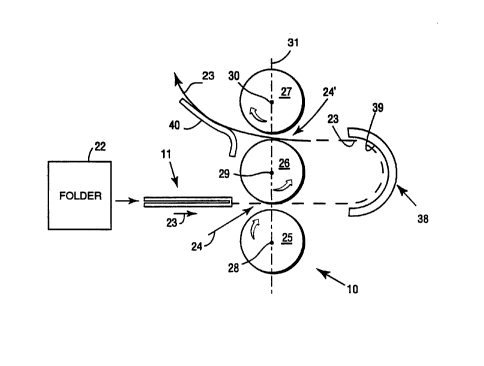
FIGURE 1 is a schematic side view of exemplary apparatus for handling
business forms according to the present invention;
FIGURE 2 is a top plan view of an exemplary business form utilized with the
equipment of FIGURE 1 before folding thereof;
FIGURE 3 is a schematic end view showing bearings and drives of exemplary
rollers of the apparatus of FIGURE 1; and
FIGURE 4 is a side schematic view of an alternative re-directing device that
may
be utilized in the apparatus of FIGURE 1.
DETAILED DESCRIPTION OF THE DRAWINGS
Exemplary sealing apparatus 10 for sealing business forms 11 in the practice
of
the method according to the present invention is shown schematically in
FIGURES 1
and 3. The business forms 11 with which the apparatus 10 are typically used --
as
seen in detail in one exemplary embodiment in FIGURE 2 (before folding) --
typically
comprises mailer type business forms typically formed of a single sheet of
paper 12
having end edges 13, 14 substantially parallel to each other -- and side edges
15, 16
substantially parallel to each other and substantially transverse to the end
edges 13,
14. The sheet 12 has one or more fold lines 17 and cooperating marginal
patterns (e.g.
strips) of pressure activated adhesive or cohesive 18, 19 as well as possibly
transverse
patterns (strips) 20. Perforation lines 21, or like lines of weakness, define
tear-off strips
CA 02310284 2000-OS-16
WO 00!16994 5 PCT/US99/20440- _
in which the longitudinal strips 18, 19 are provided. The pressure activated
adhesive or -
cohesive i8-20 may be the commercial TN124 product, and/or the other products
as
described in the patents referenced above.
For the particular business form 11 illustrated in FIGURES 1 and 2, it
comprises
a V-fold form, in which the sheet 12 is folded about the fold lines 17 so that
the strips 18
come into contact with other, and the strips 19 into contact with each other,
and the
strips 20 -- if present -- come into contact with each other. By applying
suitable
pressure to the outside of the form the strips 18-20 are sealed to each other.
While a V-fold form is illustrated in FIGURES 1 and 2 it is to be understood
that
virtually any form configuration can be provided, including C-fold (including
eccentric
C-fold), Z-fold (including eccentric Z-fold), double fold, or even overlapping
sheets or
webs unattached at all four edges. The business forms of course typically have
indicia
printed on the inside panels (and address indicia on the outside of the
mailer), and may
or may not include inserts.
Typically, a mailer 11 is passed into conventional automatic folder 22 (see
FIGURE 1 ), at which it is folded about the fold lines 17, and then passes in
the path 23
to a first nip 24 disposed between first and second rollers 25, 26,
respectively, the
rollers 25, 26 being part of a set of a plurality of rollers which also
includes at least the
third roller 27, and sometimes the roller set consisting of the rollers 25,
26, 27. Each of
the rollers 25-27 is rotatabfe about an axis of rotation 28, 29, 30,
respectively.
Preferably the axes of rotation 28-30 are substantially horizontal, and are
vertically
spaced from each other. In the preferred embodiment illustrated the axes 28-30
are
substantially vertically aligned, as indicated by the common center line 31. A
second
nip 24' is provided between the second and third rollers 26, 27, the second
roller 26
being vertically intermediate the rollers 25, 27. While in the preferred
embodiment the
first roller 25 is the lowest roller, the apparatus 10 may be constructed so
that the roller
27 is the lowest roller.
While the rollers 25-27 may have a wide variety of different constructions and
be
mounted with respect to each other in a wide variety of manners, one such
manner is
schematically illustrated in FIGURE 3 in which each of the axes 28-30 is
defined by a
shaft with the same reference numeral, the shaft mounted at its ends (and
perhaps at
intermediate locations) by conventional bearings 32, and a second roller 26
driven by a
conventional motor (such as an electric motor) 33. Preferably all three
rollers 25-27 are
CA 02310284 2000-OS-16
WO 00/16994 6 PCT/US99/20440-
driven. This may be accomplished, for example, by driving the shaft 29 for
roller 26 -
with the motor 33, with a suitable gearing arrangement -- illustrated
schematically by
the gears 34-36 in FIGURE 10 -- for driving the shafts 28, 30 /rollers 25, 27,
the rollers
rotating in the direction illustrated by the arrows in FIGURE 1.
For simplicity of illustration in FIGURES 1 and 3 the rollers 25-27 are shown
spaced from each other, but it is to be understood that they may be biased
(e.g. with ~-
coil or other springs) together or into contact with each other, or otherwise
mounted so
that they provide high compression and sealing forces to the business form 11
or like
sheets or webs passing between them. Preferably, for both the compression
stage
defined by the first nip 24 and the sealing stage defined by the second nip
24', a high
force is applied by the rollers 25-27 to the business form 71 or the like. For
example, in
both of the stages defined by the nips 24, 24' a force of at least about 100
pounds per
lineal inch, preferably a force between about 100-200 pounds per lineal inch.
The
axes/shafts 28-30 are preferably substantially vertically aligned as indicated
at 31 in
FIGURE 1 so that different forms (or the same web) can be present in both the
nips 24,
24' at the same time, maximizing the pressure in both the compression and
sealing
stages defined by the nips 24, 24'.
The rollers 25-27 may have any of the configurations such as illustrated in
the
rollers shown in U.S. patents 5,169,489, 5,378,303, 5,397,427 and 5,527,416.
The
rollers may be constructed so that they have a small width (axial length),
e.g. less than
5 inches, and typically have a diameter of about 2-4 inches. If they have such
a small
width, which is used for only edge sealing forms (e.g. just along where the
strips 18, 19
are) then distinct sets of rollers corresponding to each of the rollers 25-27
may be
provided. Alternatively, the distinct small axial edge sealing rollers may be
mounted on
the common shafts 28, 30, with the roller segments 25, 25' and 27, 27' spaced
from
each other a distance corresponding to the spacing of the adhesive/cohesive
strips 18,
19 expected. The roller 26 may also have a small axial width like that of the
roller
segments 27, 2T and 25, 25', or may extend the complete length of the shaft
29, and
the position of at least one of the rollers 25, 25' or 27, 27' may be
adjustable along the
length of the shafts 28, 30 (such as by using conventional splines, set
screws, etc.).
Alternatively, all of the rollers 25-27 may be long, so that they do not
merely seal along
the peripheral edges of the form 71, but rather seal across the entire width
of the form
11, including any transverse strips of adhesivelcohesive, such as the strips
20,
CA 02310284 2000-OS-16
WO 00/16994 7 PCT/US99/20440-
illustrated in FIGURE 2. Edge sealing is preferred when there are substantial
inserts,
whereas steam roll sealing (across the entire width of the form 11 moving in
the path
23) is preferred when there are no inserts.
The preferred sealing apparatus according to the present invention also
comprises a means for changing the direction of movement of a web or sheet
(e.g.
business form 11 ) passing through the first nip 24 to direct the web or sheet
(e.g.
business form 11 ) toward the second nip 24' while the web or sheet (e.g.
business form
11 ) is spaced from the second roller 26 when moving between nips 24, 24'.
Such
means may comprise any conventional or subsequently developed structure that
is
capable of performing that change of direction of movement function, and
particularly
so that in the preferred embodiment one business form 11 may be in the
compression
stage between the rollers 25, 26 at nip 24, while another business form is in
the sealing
stage at nip 24'. Two different embodiments are illustrated for structures
that may be
used as the means for changing the direction of movement, one illustrated in
FIGURE 1
and the other in FIGURE 4.
FIGURE 1 schematically illustrates one form of the means for changing the
direction of the web 38 comprising a substantially semicircular stationary
surface 39
which engages the business form 11 or other web or sheet and re-directs the
path of
movement 23 of the business form 11 or the like so that it moves toward the
nip 24'.
For clarity of illustration the structure 38 is illustrated in FIGURE 1 widely
spaced from
the rollers 25-27, but it typically would be located closer thereto, depending
upon the
dimensions of the business form 11 or the like. The surface 39 may be made of
a low
friction material, such as polytetrafluorethylene, or may have rollers or like
low friction
devices thereon. Alternatively, the surface 39 may have a like surface
associated
therewith defining a gap between them to define a positive guide to the form
11 as it
moves in the path 23.
After the form 11 or the like exits the nip 24' it typically is deflected, as
indicated
by the conventional stationary deflector 40 in FIGURE 1, then moves to any
subsequent handling desired, using any suitable equipment for that purpose.
For
example, other sets of driven rollers may engage the business form 11, move it
to a
stack, a pallet, a conveyor, or any other suitable location or equipment.
Another exemplary form that the means for changing the direction of movement
of the business from 11 or other web or sheet may take is illustrated
schematically in
CA 02310284 2000-OS-16
WO 00/16994 8 PCT/US99/20440-
FIGURE 4 and comprises a plurality of sets of re-directing rollers 42-44, with
or without -
conventional stationary deflectors 41, 45, 46, 47 associated therewith to
facilitate the
re-direction. When used the rollers 42-44 typically are powered, or at least
one roller of
each set is powered, using a common drive or the like. It is to be understood,
however,
that a wide variety of other re-directing means may also be provided,
including any
conventional structures capable of performing that function. w
Utilizing the apparatus 10 a method of handling business forms with pressure
activated adhesive or cohesive 18, 19 (and possibly 20) thereon is provided
which may
comprise the following: (a) Feeding a business form 11 with pressure activated
adhesive or cohesive 18, 19 thereon into and through the first nip 24 (as by
using the
conveyor, rollers, or merely the output from the conventional folder 22
itself) to effect
compression. (b) Changing the direction of movement of the business form 11 to
direct
the business form toward the second nip 24' (e.g. using the surface 39, the
sets of re-
directing rollers 42-44, or the like). And (c) feeding the business form 11
into and
through the second nip 24' to effect sealing of the pressure activated
adhesive or
cohesive 18, 19 on that part of the business form between the rollers 26, 27.
Preferably {a) through (c) are practiced by driving each of the first through,
second, and
third rollers 25-27, (c) is practiced to apply a force to the business form 11
between the
second and third rollers 26, 27 of between about 100-200 pounds per lineal
inch, and
(a) is typically practiced to apply a force to the business form 11 between
the rollers 25,
26 of between about 100-200 pounds per lineal inch. (a} and (c) are also
typically
practiced to operate on two different forms 11 at the same time. The method
may be
practiced on a business form having the pressure activated cohesive or
adhesive strips
18, 19 along the two peripheral portions thereof as illustrated in FIGURE 2
with (a) and
(c) practiced to act substantially only on the peripheral portions of the
form.
Alternatively, especially where the form 11 has one or more transverse strips
of
adhesive or cohesive 20, (a) and (c) are practiced to act substantially along
the entire
width of the business form 11 to also sea! the adhesive or cohesive 20 while
sealing the
strips 18, 19.
While the invention has been herein shown and described in what is presently
conceived to be the most practical and preferred embodiment thereof it will be
apparent
to those of ordinary skill in the art that many modifications may be made
thereof within
CA 02310284 2000-OS-16
WO 00/16994 9 PCTIUS99/2044Q
the scope of the invention, which scope is to be accorded the broadest
interpretation of
the appended claims so as to encompass all equivalent structures and methods.