Language selection

Search

Patent 2310301 Summary

Third-party information liability

Some of the information on this Web page has been provided by external sources. The Government of Canada is not responsible for the accuracy, reliability or currency of the information supplied by external sources. Users wishing to rely upon this information should consult directly with the source of the information. Content provided by external sources is not subject to official languages, privacy and accessibility requirements.

Claims and Abstract availability

Any discrepancies in the text and image of the Claims and Abstract are due to differing posting times. Text of the Claims and Abstract are posted:

  • At the time the application is open to public inspection;
  • At the time of issue of the patent (grant).
(12) Patent: (11) CA 2310301
(54) English Title: BENDING MACHINE FOR SHEET METAL PANELS WITH HIGH EDGES
(54) French Title: CINTREUSE DE PANNEAUX EN TOLE AVEC REBORDS HAUTS
Status: Deemed expired
Bibliographic Data
(51) International Patent Classification (IPC):
  • B21D 5/00 (2006.01)
  • B21D 5/04 (2006.01)
(72) Inventors :
  • VENTURINI, GIANFRANCO (Italy)
(73) Owners :
  • SALVAGNINI ITALIA S.P.A. (Italy)
(71) Applicants :
  • SALVAGNINI ITALIA S.P.A. (Italy)
(74) Agent: RICHES, MCKENZIE & HERBERT LLP
(74) Associate agent:
(45) Issued: 2006-11-28
(22) Filed Date: 2000-05-30
(41) Open to Public Inspection: 2000-12-03
Examination requested: 2004-04-16
Availability of licence: N/A
(25) Language of filing: English

Patent Cooperation Treaty (PCT): No

(30) Application Priority Data:
Application No. Country/Territory Date
MI99A 001245 Italy 1999-06-03

Abstracts

English Abstract

Bending machine for sheet metal panels with high edges, comprising a counter blade fixedly mounted to a stationary base, a mobile blank holder placed above the counter blade, a turnable support for blank holder that is hinged to said stationary base, first moving means connected with the turnable support in order to control its rotation with respect to the stationary base, the blank holder being connected with the turnable support in such a way so as to be able to slide upward and downward with respect to it and second moving means are provided that are suitable to control the sliding of the same blank holder with respect to the turnable support.


French Abstract

Une machine à cintrer pour des panneaux en tôle ayant des bords élevés, laquelle machine à cintrer comprend une contre lame montée de manière fixe sur une base immobile, un serre-flan mobile placé au-dessus de la contre-lame, un support rotatif pour serre-flan qui est articulé à ladite base immobile, des premiers moyens mobiles reliés au support rotatif de façon à commander sa rotation par rapport à la base immobile, le serre-flan étant relié au support rotatif de façon à être apte à coulisser vers le haut et vers le bas par rapport à celui-ci et des seconds moyens mobiles sont prévus, lesquels sont appropriés pour commander le coulissement dudit serre-flan par rapport au support rotatif.

Claims

Note: Claims are shown in the official language in which they were submitted.


6


CLAIMS

1. Bending machine for sheet metal panels with high edges, comprising
a counter blade that is fixedly mounted to a stationary base, a mobile blank
holder that is placed above the counter blade, a turnable support for blank
holder that is hinged to said stationary base, first moving means connected
with said turnable support in order to control its rotation with reference to
said stationary base, characterized in that said blank holder is connected
with
said turnable support in order to be able to slide upward and downward with
respect to it and second moving means suitable to control the sliding of the
same blank holder with respect to said turnable support are provided.

2. Bending machine according to claim 1, characterized in that said
blank holder is fixed to a slidable support that is capable to slide
vertically
on guides that are fixedly mounted to said turnable support and said second
moving means comprise at least a hydraulic cylinder that is held by said
turnable support.

3. Bending machine according to claim 2, characterized in that said
slidable support is connected with a piston rod of said hydraulic cylinder by
means of a perpendicular extension of its upper end.

4. Bending machine according to claim 3, characterized in that said
cylinder is housed inside said turnable support and is parallel to the blank
holder.

5. Bending machine according to claim 1 or 4, characterized in that said
first moving means comprise a plurality of hydraulic cylinders and relative
rods, the first ones of which are hinged to said turnable support and the
second ones to the stationary base.

Description

Note: Descriptions are shown in the official language in which they were submitted.


CA 02310301 2000-OS-30
1
"Bending machine for sheet metal panels with high edges."
*****
DESCRIPTION
The present invention refers to a bending machine for sheet metal panels
with high edges.
There are known bending machines for sheet metal panels in which the
sheet metal panel to be bent, arranged horizontally, is initially squeezed
between two bodies, a lower one called "counter blade," that is fixedly
mounted to the base of the machine and operates as a support for the sheet
metal panel, and an upper one called "blank holder", that is mobile between
. a raised position for the introduction of the sheet metal panel and a
lowered
position in which its resting foot cooperates with the counter blade in order
to hold and to keep the same sheet in position. The sheet metal is positioned
in such a way that one of its edges, that is destined to be bent, projects
horizontally as regards the edges of the counter blade and of the blank
holder. The sheet metal is then bent upward by a lower bending blade or
downward by an upper bending blade that is situated above said edge. Said
upper and lower blades form a pair of bending blades that are usually fixedly
mounted to a common support that is displaceable by independent operation
which is combinable in vertical and horizontal direction. A machine of this
kind has been described, for instance, in the European patent No. 0293964.
In the aforesaid machine the blank holder is hinged onto the back part of
the base and it is driven to rotate by hydraulic cylinders whose rods are
hinged to the base, and therefore the trajectory described by the blank holder
in its lowering and lifting movements is not really rectilinear but is an arc
of
circumference. This does not allow the bending of sheet metal panels having
very high edges since the impact of the blank holder foot with the folded
edge would be inevitable during the lifting of the same blank holder.
In view of the state of the art herein described, object of the present
invention is to realise a bending machine that allows to bend sheet metal

CA 02310301 2000-OS-30
2
with high edges while preventing any impact of the blank holder foot with
the folded edge of the sheet metal panels.
According to the present invention, such object is attained by means of a
bending machine for sheet metal panels with high edges comprising a
counter blade that is fixedly mounted to a stationary base, a mobile blank
holder placed above the counter blade, a turnable support for blank holder
that is hinged to said stationary base, first moving means connected with
said turnable support so as to control its rotation with respect to said
stationary base, characterized in that said blank holder is connected with
said
turnable support in such a way so as to be able to slide upward and
downward with respect to it and second moving means are provided that are
suitable to control the sliding of the same blank holder with respect to said
turnable support.
Thanks to the present invention a bending machine for sheet metal
1 S panels with high edges has been realised that, besides the usual rotary
motion, allows the blank holder a substantially rectilinear vertical sliding
motion, thus preventing the impact of the same blank holder with the folded
edge of the sheet metal panels.
The characteristics and the advantages of the present invention will
become evident from the following detailed description of an embodiment
thereof that is illustrated as a non limiting example in the enclosed
drawings,
in which:
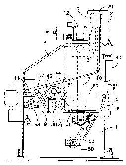
Figure 1 is a vertical side view of a bending machine according to an
embodiment of the present invention;
Figure 2 is similar to Figure 1 but with the blank holder foot lowered in
order to allow the bending of the edge of a sheet metal panel;
Figure 3 is similar to Figure 2 but with the blank holder foot lifted in
order to allow the extraction of the sheet metal panel with folded edge.
In the annexed figures a bending machine according to the invention is
shown comprising a base 1 to which a counter blade 5 is frontally fixed, that

CA 02310301 2000-OS-30
3
serves as resting support for a sheet metal panel to be bent; a blank holder
40
with a bearing foot 55 is superimposed on the counter blade 5 and is fixed to
the lower end of a slidable support 2. Said slidable support 2 is capable to
slide vertically on guides 10 and it is fixedly mounted through a
perpendicular extension 20 of its upper end to one or more piston rods 7,
each belonging to a hydraulic cylinder 3 that is parallel to the same slidable
support 2 and housed in a turnable support 4. At the back end of the machine
said turnable support 4 is hinged at 11 between two supports 9 that are
fixedly mounted to the base 1.
The turnable support 4 is movable owing to a linear sequence of
hydraulic cylinders 12 (a single one shown in Figure 1 ) whose rods 13 are
hinged to the base 1.
Between the base 1 and the support 4 a bending blade 8 with relative
blade holder 43 and a unit S 1 for its moving are housed. The blade holder 43
is vertically crossed by the rods 13 of the cylinders 12 and at the end
opposite to the blade 8 it is hinged to a crank 44 that is hinged at 30 to a
support 45 that is fixedly mounted to the base 1; this crank 44 is in turn
hinged to a rod 46 of a hydraulic cylinder 47 that is fixedly mounted to the
supports 9. The support 43 for the bending blade 8 is provided with a bottom
flange 49 that is hinged to a rod of an additional hydraulic cylinder,
rendered
only by its axis 53 in the figures, that is fixed to the base 1 at a point 50.
The hydraulic cylinders 12 cause a movement of the blank holder 40
according to a circumference arc trajectory, since the support 4 rotates
around a horizontal axis passing through the hinge points 11 of the same
support 4 with the support 9 fixedly mounted to the base 1. More precisely
the extension of the rods 13 causes the lifting of the blank holder 40, while
their reversal causes the lowering of the blank holder 40 onto the sheet metal
panel 6, so as to keep the latter in position on the counter blade 5 during
its
bending.
The bending blade 8 is mobile both in horizontal sense and in vertical

CA 02310301 2000-OS-30
4
sense owing to the moving unit 51; the extension or the retraction of the rod
46 of the hydraulic cylinder 47 causes the rotation of the crank 44, which
causes the. forward or back movement of the blade holder 43 and therefore of
the blade 8. The hydraulic cylinder 53 instead causes a motion of rotation of
the same blade holder 43 around the horizontal rotation axis passing through
the hinge point 30 of the crank 44, motion that translates into a
substantially
vertical movement of the bending blade 8.
The hydraulic cylinder 3 instead causes the rectilinear vertical
movement of the blank holder 40 as regards the counter blade 5. In fact the
extension or the retraction of the rod 7 of the hydraulic cylinder 3
respectively allows the lifting or the lowering of the slidable support 2 to
which the blank holder 40 is fixedly mounted and that is capable to slide
through the guides 10.
The main advantage of the rectilinear vertical motion of the blank
holder 40 is clearly observable in Figures 2 and 3.
Figure 2 shows a bending machine with a blank holder 40 that is
lowered in order to co-operate with the counter blade 5 so as to press a sheet
metal panel 6, that is positioned in a such way that an edge of the same,
indicated by 60, projects inside the space between the base 1 and the support
4.
In a following phase the blank holder 40 co-operates with the blade 8 in
order to allow the latter to bend the edge 60 upward in such a way that it
forms a substantially straight angle with the remaining part of the sheet
metal panel 6. At this point the sole rotation of the turnable support 4 of
the
blank holder 40 around the axis 11 would not be enough to allow the bearing
foot 55 to get far from the counter blade 5 without hitting the folded edge 60
of the sheet metal panel.
Owing to the cylinders 3 it is however possible to impose the blank
holder 40 a previous vertical sliding upward, that allows then the blank
holder 40 to follow the rotation of the support 4 without any damage for the


Image

Representative Drawing
A single figure which represents the drawing illustrating the invention.
Administrative Status

For a clearer understanding of the status of the application/patent presented on this page, the site Disclaimer , as well as the definitions for Patent , Administrative Status , Maintenance Fee  and Payment History  should be consulted.

Administrative Status

Title Date
Forecasted Issue Date 2006-11-28
(22) Filed 2000-05-30
(41) Open to Public Inspection 2000-12-03
Examination Requested 2004-04-16
(45) Issued 2006-11-28
Deemed Expired 2018-05-30

Abandonment History

There is no abandonment history.

Payment History

Fee Type Anniversary Year Due Date Amount Paid Paid Date
Registration of a document - section 124 $100.00 2000-05-30
Application Fee $300.00 2000-05-30
Maintenance Fee - Application - New Act 2 2002-05-30 $100.00 2002-04-19
Maintenance Fee - Application - New Act 3 2003-05-30 $100.00 2003-04-11
Request for Examination $800.00 2004-04-16
Maintenance Fee - Application - New Act 4 2004-05-31 $100.00 2004-05-20
Maintenance Fee - Application - New Act 5 2005-05-30 $200.00 2005-04-19
Maintenance Fee - Application - New Act 6 2006-05-30 $200.00 2006-04-24
Final Fee $300.00 2006-09-08
Maintenance Fee - Patent - New Act 7 2007-05-30 $200.00 2007-04-23
Maintenance Fee - Patent - New Act 8 2008-05-30 $200.00 2008-04-30
Maintenance Fee - Patent - New Act 9 2009-06-01 $200.00 2009-05-01
Maintenance Fee - Patent - New Act 10 2010-05-31 $250.00 2010-04-26
Maintenance Fee - Patent - New Act 11 2011-05-30 $250.00 2011-04-29
Maintenance Fee - Patent - New Act 12 2012-05-30 $250.00 2012-05-23
Maintenance Fee - Patent - New Act 13 2013-05-30 $250.00 2013-05-17
Maintenance Fee - Patent - New Act 14 2014-05-30 $250.00 2014-05-21
Maintenance Fee - Patent - New Act 15 2015-06-01 $450.00 2015-04-09
Maintenance Fee - Patent - New Act 16 2016-05-30 $450.00 2016-04-19
Owners on Record

Note: Records showing the ownership history in alphabetical order.

Current Owners on Record
SALVAGNINI ITALIA S.P.A.
Past Owners on Record
VENTURINI, GIANFRANCO
Past Owners that do not appear in the "Owners on Record" listing will appear in other documentation within the application.
Documents

To view selected files, please enter reCAPTCHA code :


To view images, click a link in the Document Description column. To download the documents, select one or more checkboxes in the first column and then click the "Download Selected in PDF format (Zip Archive)" or the "Download Selected as Single PDF" button.

List of published and non-published patent-specific documents on the CPD .

If you have any difficulty accessing content, you can call the Client Service Centre at 1-866-997-1936 or send them an e-mail at CIPO Client Service Centre.


Document
Description 
Date
(yyyy-mm-dd) 
Number of pages   Size of Image (KB) 
Claims 2000-05-30 1 39
Drawings 2000-05-30 3 80
Representative Drawing 2000-11-29 1 13
Abstract 2000-05-30 1 19
Description 2000-05-30 5 197
Cover Page 2000-11-29 1 39
Representative Drawing 2006-11-02 1 12
Cover Page 2006-11-02 1 41
Assignment 2000-05-30 4 116
Fees 2003-04-11 1 34
Fees 2008-04-30 1 54
Fees 2006-04-24 1 34
Fees 2002-04-19 1 36
Prosecution-Amendment 2004-04-16 1 37
Fees 2004-05-20 1 36
Prosecution-Amendment 2004-06-08 2 41
Fees 2005-04-19 1 32
Correspondence 2006-09-08 1 50
Fees 2007-04-23 1 45
Fees 2009-05-01 1 54
Fees 2010-04-26 1 54
Fees 2011-04-29 1 52
Fees 2012-05-23 1 53
Fees 2013-05-17 1 52
Fees 2014-05-21 1 56
Fees 2015-04-09 1 55