Sélection de la langue

Search

Sommaire du brevet 2310301 

Énoncé de désistement de responsabilité concernant l'information provenant de tiers

Une partie des informations de ce site Web a été fournie par des sources externes. Le gouvernement du Canada n'assume aucune responsabilité concernant la précision, l'actualité ou la fiabilité des informations fournies par les sources externes. Les utilisateurs qui désirent employer cette information devraient consulter directement la source des informations. Le contenu fourni par les sources externes n'est pas assujetti aux exigences sur les langues officielles, la protection des renseignements personnels et l'accessibilité.

Disponibilité de l'Abrégé et des Revendications

L'apparition de différences dans le texte et l'image des Revendications et de l'Abrégé dépend du moment auquel le document est publié. Les textes des Revendications et de l'Abrégé sont affichés :

  • lorsque la demande peut être examinée par le public;
  • lorsque le brevet est émis (délivrance).
(12) Brevet: (11) CA 2310301
(54) Titre français: CINTREUSE DE PANNEAUX EN TOLE AVEC REBORDS HAUTS
(54) Titre anglais: BENDING MACHINE FOR SHEET METAL PANELS WITH HIGH EDGES
Statut: Périmé et au-delà du délai pour l’annulation
Données bibliographiques
(51) Classification internationale des brevets (CIB):
  • B21D 5/00 (2006.01)
  • B21D 5/04 (2006.01)
(72) Inventeurs :
  • VENTURINI, GIANFRANCO (Italie)
(73) Titulaires :
  • SALVAGNINI ITALIA S.P.A.
(71) Demandeurs :
  • SALVAGNINI ITALIA S.P.A. (Italie)
(74) Agent: RICHES, MCKENZIE & HERBERT LLP
(74) Co-agent:
(45) Délivré: 2006-11-28
(22) Date de dépôt: 2000-05-30
(41) Mise à la disponibilité du public: 2000-12-03
Requête d'examen: 2004-04-16
Licence disponible: S.O.
Cédé au domaine public: S.O.
(25) Langue des documents déposés: Anglais

Traité de coopération en matière de brevets (PCT): Non

(30) Données de priorité de la demande:
Numéro de la demande Pays / territoire Date
MI99A 001245 (Italie) 1999-06-03

Abrégés

Abrégé français

Une machine à cintrer pour des panneaux en tôle ayant des bords élevés, laquelle machine à cintrer comprend une contre lame montée de manière fixe sur une base immobile, un serre-flan mobile placé au-dessus de la contre-lame, un support rotatif pour serre-flan qui est articulé à ladite base immobile, des premiers moyens mobiles reliés au support rotatif de façon à commander sa rotation par rapport à la base immobile, le serre-flan étant relié au support rotatif de façon à être apte à coulisser vers le haut et vers le bas par rapport à celui-ci et des seconds moyens mobiles sont prévus, lesquels sont appropriés pour commander le coulissement dudit serre-flan par rapport au support rotatif.


Abrégé anglais

Bending machine for sheet metal panels with high edges, comprising a counter blade fixedly mounted to a stationary base, a mobile blank holder placed above the counter blade, a turnable support for blank holder that is hinged to said stationary base, first moving means connected with the turnable support in order to control its rotation with respect to the stationary base, the blank holder being connected with the turnable support in such a way so as to be able to slide upward and downward with respect to it and second moving means are provided that are suitable to control the sliding of the same blank holder with respect to the turnable support.

Revendications

Note : Les revendications sont présentées dans la langue officielle dans laquelle elles ont été soumises.


6
CLAIMS
1. Bending machine for sheet metal panels with high edges, comprising
a counter blade that is fixedly mounted to a stationary base, a mobile blank
holder that is placed above the counter blade, a turnable support for blank
holder that is hinged to said stationary base, first moving means connected
with said turnable support in order to control its rotation with reference to
said stationary base, characterized in that said blank holder is connected
with
said turnable support in order to be able to slide upward and downward with
respect to it and second moving means suitable to control the sliding of the
same blank holder with respect to said turnable support are provided.
2. Bending machine according to claim 1, characterized in that said
blank holder is fixed to a slidable support that is capable to slide
vertically
on guides that are fixedly mounted to said turnable support and said second
moving means comprise at least a hydraulic cylinder that is held by said
turnable support.
3. Bending machine according to claim 2, characterized in that said
slidable support is connected with a piston rod of said hydraulic cylinder by
means of a perpendicular extension of its upper end.
4. Bending machine according to claim 3, characterized in that said
cylinder is housed inside said turnable support and is parallel to the blank
holder.
5. Bending machine according to claim 1 or 4, characterized in that said
first moving means comprise a plurality of hydraulic cylinders and relative
rods, the first ones of which are hinged to said turnable support and the
second ones to the stationary base.

Description

Note : Les descriptions sont présentées dans la langue officielle dans laquelle elles ont été soumises.

CA 02310301 2000-OS-30
1
"Bending machine for sheet metal panels with high edges."
*****
DESCRIPTION
The present invention refers to a bending machine for sheet metal panels
with high edges.
There are known bending machines for sheet metal panels in which the
sheet metal panel to be bent, arranged horizontally, is initially squeezed
between two bodies, a lower one called "counter blade," that is fixedly
mounted to the base of the machine and operates as a support for the sheet
metal panel, and an upper one called "blank holder", that is mobile between
. a raised position for the introduction of the sheet metal panel and a
lowered
position in which its resting foot cooperates with the counter blade in order
to hold and to keep the same sheet in position. The sheet metal is positioned
in such a way that one of its edges, that is destined to be bent, projects
horizontally as regards the edges of the counter blade and of the blank
holder. The sheet metal is then bent upward by a lower bending blade or
downward by an upper bending blade that is situated above said edge. Said
upper and lower blades form a pair of bending blades that are usually fixedly
mounted to a common support that is displaceable by independent operation
which is combinable in vertical and horizontal direction. A machine of this
kind has been described, for instance, in the European patent No. 0293964.
In the aforesaid machine the blank holder is hinged onto the back part of
the base and it is driven to rotate by hydraulic cylinders whose rods are
hinged to the base, and therefore the trajectory described by the blank holder
in its lowering and lifting movements is not really rectilinear but is an arc
of
circumference. This does not allow the bending of sheet metal panels having
very high edges since the impact of the blank holder foot with the folded
edge would be inevitable during the lifting of the same blank holder.
In view of the state of the art herein described, object of the present
invention is to realise a bending machine that allows to bend sheet metal

CA 02310301 2000-OS-30
2
with high edges while preventing any impact of the blank holder foot with
the folded edge of the sheet metal panels.
According to the present invention, such object is attained by means of a
bending machine for sheet metal panels with high edges comprising a
counter blade that is fixedly mounted to a stationary base, a mobile blank
holder placed above the counter blade, a turnable support for blank holder
that is hinged to said stationary base, first moving means connected with
said turnable support so as to control its rotation with respect to said
stationary base, characterized in that said blank holder is connected with
said
turnable support in such a way so as to be able to slide upward and
downward with respect to it and second moving means are provided that are
suitable to control the sliding of the same blank holder with respect to said
turnable support.
Thanks to the present invention a bending machine for sheet metal
1 S panels with high edges has been realised that, besides the usual rotary
motion, allows the blank holder a substantially rectilinear vertical sliding
motion, thus preventing the impact of the same blank holder with the folded
edge of the sheet metal panels.
The characteristics and the advantages of the present invention will
become evident from the following detailed description of an embodiment
thereof that is illustrated as a non limiting example in the enclosed
drawings,
in which:
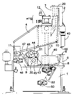
Figure 1 is a vertical side view of a bending machine according to an
embodiment of the present invention;
Figure 2 is similar to Figure 1 but with the blank holder foot lowered in
order to allow the bending of the edge of a sheet metal panel;
Figure 3 is similar to Figure 2 but with the blank holder foot lifted in
order to allow the extraction of the sheet metal panel with folded edge.
In the annexed figures a bending machine according to the invention is
shown comprising a base 1 to which a counter blade 5 is frontally fixed, that

CA 02310301 2000-OS-30
3
serves as resting support for a sheet metal panel to be bent; a blank holder
40
with a bearing foot 55 is superimposed on the counter blade 5 and is fixed to
the lower end of a slidable support 2. Said slidable support 2 is capable to
slide vertically on guides 10 and it is fixedly mounted through a
perpendicular extension 20 of its upper end to one or more piston rods 7,
each belonging to a hydraulic cylinder 3 that is parallel to the same slidable
support 2 and housed in a turnable support 4. At the back end of the machine
said turnable support 4 is hinged at 11 between two supports 9 that are
fixedly mounted to the base 1.
The turnable support 4 is movable owing to a linear sequence of
hydraulic cylinders 12 (a single one shown in Figure 1 ) whose rods 13 are
hinged to the base 1.
Between the base 1 and the support 4 a bending blade 8 with relative
blade holder 43 and a unit S 1 for its moving are housed. The blade holder 43
is vertically crossed by the rods 13 of the cylinders 12 and at the end
opposite to the blade 8 it is hinged to a crank 44 that is hinged at 30 to a
support 45 that is fixedly mounted to the base 1; this crank 44 is in turn
hinged to a rod 46 of a hydraulic cylinder 47 that is fixedly mounted to the
supports 9. The support 43 for the bending blade 8 is provided with a bottom
flange 49 that is hinged to a rod of an additional hydraulic cylinder,
rendered
only by its axis 53 in the figures, that is fixed to the base 1 at a point 50.
The hydraulic cylinders 12 cause a movement of the blank holder 40
according to a circumference arc trajectory, since the support 4 rotates
around a horizontal axis passing through the hinge points 11 of the same
support 4 with the support 9 fixedly mounted to the base 1. More precisely
the extension of the rods 13 causes the lifting of the blank holder 40, while
their reversal causes the lowering of the blank holder 40 onto the sheet metal
panel 6, so as to keep the latter in position on the counter blade 5 during
its
bending.
The bending blade 8 is mobile both in horizontal sense and in vertical

CA 02310301 2000-OS-30
4
sense owing to the moving unit 51; the extension or the retraction of the rod
46 of the hydraulic cylinder 47 causes the rotation of the crank 44, which
causes the. forward or back movement of the blade holder 43 and therefore of
the blade 8. The hydraulic cylinder 53 instead causes a motion of rotation of
the same blade holder 43 around the horizontal rotation axis passing through
the hinge point 30 of the crank 44, motion that translates into a
substantially
vertical movement of the bending blade 8.
The hydraulic cylinder 3 instead causes the rectilinear vertical
movement of the blank holder 40 as regards the counter blade 5. In fact the
extension or the retraction of the rod 7 of the hydraulic cylinder 3
respectively allows the lifting or the lowering of the slidable support 2 to
which the blank holder 40 is fixedly mounted and that is capable to slide
through the guides 10.
The main advantage of the rectilinear vertical motion of the blank
holder 40 is clearly observable in Figures 2 and 3.
Figure 2 shows a bending machine with a blank holder 40 that is
lowered in order to co-operate with the counter blade 5 so as to press a sheet
metal panel 6, that is positioned in a such way that an edge of the same,
indicated by 60, projects inside the space between the base 1 and the support
4.
In a following phase the blank holder 40 co-operates with the blade 8 in
order to allow the latter to bend the edge 60 upward in such a way that it
forms a substantially straight angle with the remaining part of the sheet
metal panel 6. At this point the sole rotation of the turnable support 4 of
the
blank holder 40 around the axis 11 would not be enough to allow the bearing
foot 55 to get far from the counter blade 5 without hitting the folded edge 60
of the sheet metal panel.
Owing to the cylinders 3 it is however possible to impose the blank
holder 40 a previous vertical sliding upward, that allows then the blank
holder 40 to follow the rotation of the support 4 without any damage for the

<IMG>

Dessin représentatif
Une figure unique qui représente un dessin illustrant l'invention.
États administratifs

2024-08-01 : Dans le cadre de la transition vers les Brevets de nouvelle génération (BNG), la base de données sur les brevets canadiens (BDBC) contient désormais un Historique d'événement plus détaillé, qui reproduit le Journal des événements de notre nouvelle solution interne.

Veuillez noter que les événements débutant par « Inactive : » se réfèrent à des événements qui ne sont plus utilisés dans notre nouvelle solution interne.

Pour une meilleure compréhension de l'état de la demande ou brevet qui figure sur cette page, la rubrique Mise en garde , et les descriptions de Brevet , Historique d'événement , Taxes périodiques et Historique des paiements devraient être consultées.

Historique d'événement

Description Date
Le délai pour l'annulation est expiré 2018-05-30
Lettre envoyée 2017-05-30
Requête visant le maintien en état reçue 2015-04-09
Requête visant le maintien en état reçue 2014-05-21
Requête visant le maintien en état reçue 2013-05-17
Accordé par délivrance 2006-11-28
Inactive : Page couverture publiée 2006-11-27
Préoctroi 2006-09-08
Inactive : Taxe finale reçue 2006-09-08
Un avis d'acceptation est envoyé 2006-04-18
Lettre envoyée 2006-04-18
Un avis d'acceptation est envoyé 2006-04-18
Inactive : Approuvée aux fins d'acceptation (AFA) 2006-04-01
Inactive : CIB de MCD 2006-03-12
Modification reçue - modification volontaire 2004-06-08
Lettre envoyée 2004-04-29
Requête d'examen reçue 2004-04-16
Exigences pour une requête d'examen - jugée conforme 2004-04-16
Toutes les exigences pour l'examen - jugée conforme 2004-04-16
Demande publiée (accessible au public) 2000-12-03
Inactive : Page couverture publiée 2000-12-03
Inactive : CIB en 1re position 2000-08-07
Inactive : Certificat de dépôt - Sans RE (Anglais) 2000-07-13
Exigences de dépôt - jugé conforme 2000-07-13
Lettre envoyée 2000-07-13
Demande reçue - nationale ordinaire 2000-07-11

Historique d'abandonnement

Il n'y a pas d'historique d'abandonnement

Taxes périodiques

Le dernier paiement a été reçu le 2006-04-24

Avis : Si le paiement en totalité n'a pas été reçu au plus tard à la date indiquée, une taxe supplémentaire peut être imposée, soit une des taxes suivantes :

  • taxe de rétablissement ;
  • taxe pour paiement en souffrance ; ou
  • taxe additionnelle pour le renversement d'une péremption réputée.

Veuillez vous référer à la page web des taxes sur les brevets de l'OPIC pour voir tous les montants actuels des taxes.

Titulaires au dossier

Les titulaires actuels et antérieures au dossier sont affichés en ordre alphabétique.

Titulaires actuels au dossier
SALVAGNINI ITALIA S.P.A.
Titulaires antérieures au dossier
GIANFRANCO VENTURINI
Les propriétaires antérieurs qui ne figurent pas dans la liste des « Propriétaires au dossier » apparaîtront dans d'autres documents au dossier.
Documents

Pour visionner les fichiers sélectionnés, entrer le code reCAPTCHA :


Pour visualiser une image, cliquer sur un lien dans la colonne description du document. Pour télécharger l'image (les images), cliquer l'une ou plusieurs cases à cocher dans la première colonne et ensuite cliquer sur le bouton "Télécharger sélection en format PDF (archive Zip)" ou le bouton "Télécharger sélection (en un fichier PDF fusionné)".

Liste des documents de brevet publiés et non publiés sur la BDBC .

Si vous avez des difficultés à accéder au contenu, veuillez communiquer avec le Centre de services à la clientèle au 1-866-997-1936, ou envoyer un courriel au Centre de service à la clientèle de l'OPIC.


Description du
Document 
Date
(aaaa-mm-jj) 
Nombre de pages   Taille de l'image (Ko) 
Dessin représentatif 2000-11-29 1 13
Description 2000-05-30 5 197
Abrégé 2000-05-30 1 19
Revendications 2000-05-30 1 39
Dessins 2000-05-30 3 80
Page couverture 2000-11-29 1 39
Dessin représentatif 2006-11-02 1 12
Page couverture 2006-11-02 1 41
Courtoisie - Certificat d'enregistrement (document(s) connexe(s)) 2000-07-13 1 115
Certificat de dépôt (anglais) 2000-07-13 1 164
Rappel de taxe de maintien due 2002-01-31 1 111
Accusé de réception de la requête d'examen 2004-04-29 1 176
Avis du commissaire - Demande jugée acceptable 2006-04-18 1 162
Avis concernant la taxe de maintien 2017-07-11 1 178
Taxes 2003-04-11 1 34
Taxes 2002-04-19 1 36
Taxes 2004-05-20 1 36
Taxes 2005-04-19 1 32
Taxes 2006-04-24 1 34
Correspondance 2006-09-08 1 50
Taxes 2007-04-23 1 45
Taxes 2008-04-30 1 54
Taxes 2009-05-01 1 54
Taxes 2010-04-26 1 54
Taxes 2011-04-29 1 52
Taxes 2012-05-23 1 53
Taxes 2013-05-17 1 52
Taxes 2014-05-21 1 56
Taxes 2015-04-09 1 55