Note: Descriptions are shown in the official language in which they were submitted.
CA 02310533 2000-06-02
APPARATUS AND METHOD FOR AUTOMATICALLY ADJUSTING THE
PATH OF A SCINTILLATION CAMERA
Field
The present invention relates to the field of scintillation cameras, and
specifically
to a method and apparatus for automatically adjusting the path of a
scintillation camera.
Background
In the human body, increased metabolic activity is associated with an increase
in
emitted radiation. In the field of nuclear medicine, increased metabolic
activity within
a patient is detected using a radiation detector such as a scintillation
camera.
Scintillation cameras are well known in the art, and are used for medical
diagnostics. A patient ingests, or inhales or is injected with a small
quantity of a
radioactive isotope. The radioactive isotope emits photons that are detected
by a
scintillation medium in the scintillation camera. The scintillation medium is
commonly
a sodium iodide crystal, BGO or other. The scintillation medium emits a small
flash or
scintillation of light, in response to stimulating radiation, such as from a
patient. The
intensity of the scintillation of light is proportional to the energy of the
stimulating
photon, such as a gamma photon. Note that the relationship between the
intensity of the
scintillation of light and the gamma photon is not linear.
A conventional scintillation camera such as a gamma camera includes a detector
which converts into electrical signals gamma rays emitted from a patient after
radioisotope has been administered to the patient. The detector includes a
scintillator and
photomultiplier tubes. The gamma rays are directed to the scintillator which
absorbs the
radiation and produces, in response, a very small flash of light. An array of
photodetectors, which are placed in optical communication with the
scintillation crystal,
converts these flashes into electrical signals which are subsequently
processed. The
processing enables the camera to produce an image of the distribution of the
radioisotope
within the patient.
CA 02310533 2000-06-02
2
Gamma radiation is emitted in all directions and it is necessary to collimate
the
radiation before the radiation impinges on the crystal scintillator. This is
accomplished
by a collimator which is a sheet of absorbing material, usually lead,
perforated by
relatively narrow channels. The collimator is detachably secured to the
detector head,
allowing the collimator to be changed to enable the detector head to be used
with the
different energies of isotope to suit particular characteristics of the
patient study. A
collimator may vary considerably in weight to match the isotope or study type.
Scintillation cameras are used to take four basic types of pictures: spot
views,
whole body views, partial whole body views, SPELT views, and whole body SPELT
mews.
A spot view is an image of a part of a patient. The area of the spot view is
less
than or equal to the size of the field of view of the gamma camera. In order
to be able to
achieve a full range of spot views, a gamma camera must be positionable at any
location
relative to a patient.
One type of whole body view is a series of spot views fitted together such
that the
whole body of the patient may be viewed at one time. Another type of whole
body view
is a continuous scan of the whole body of the patient. A partial whole body
view is
simply a whole body view that covers only part of the body of the patient. In
order to be
able to achieve a whole body view, a gamma camera must be positionable at any
location
relative to a patient in an automated sequence of views.
The acronym "SPELT" stands for single photon emission computerized
tomography. A SPELT view is a series of slice-like images of the patient. The
slice-like
images are often, but not necessarily, transversely oriented with respect to
the patient.
Each slice-like image is made up of multiple views taken at different angles
around the
patient, the data from the various views being combined to form the slice-like
image. In
3 0 order to be able to achieve a SPELT view, a scintillation camera must be
rotatable around
a patient, with the direction of the detector head of the scintillation camera
pointing in
CA 02310533 2000-06-02
3
a series of known and precise directions such that reprojection of the data
can be
accurately undertaken.
A whole body SPELT view is a series of parallel slice-like transverse images
of
a patient. Typically, a whole body SPELT view consists of sixty four spaced
apart
SPELT views. A whole body SPELT view results from the simultaneous generation
of
whole body and SPELT image data. In order to be able to achieve a whole body
SPELT
view, a scintillation camera must be rotatable around a patient, with the
direction of the
detector head of the scintillation camera pointing in a series of known and
precise
directions such that reprojection of the data can be accurately undertaken.
Therefore, in order that the radiation detector be capable of achieving the
above
four basic views, the support structure for the radiation detector must be
capable of
positioning the radiation detector in any position relative to the patient.
Furthermore, the
support structure must be capable of moving the radiation detector relative to
the patient
in a controlled manner along any path.
In order to operate a scintillation camera as described above, the patient
should
be supported horizontally on a patient support or stretcher.
The detector head of the scintillation camera must be able to pass underneath
the
patient. Therefore, in order for the scintillation camera to generate images
from
underneath the patient, the patient support must be thin. However, detector
heads are
generally supported by a pair of arms which extend from a gantry. Thus, the
patient
support generally must be cantilevered in order for the detector head to be
able to pass
underneath the patient without contacting any supporting structure associated
with the
patient support. The design of a cantilevered patient support that is thin
enough to work
properly with a scintillation camera is exceedingly difficult. Expensive
materials and
materials that are difficult to work with, such as carbon fibre, are often
used in the design
of such cantilevered patient supports.
CA 02310533 2000-06-02
4
A certain design of gantry or support structure for a scintillation camera
includes
a frame upon which a vertically oriented annular support rotates. Extending
out from the
rotating support is an elongate support. The elongate generally comprises a
pair of arms.
The pair of arms generally extends through a corresponding pair of apertures
in the
rotating support. One end of the pair of arms supports the detector head on
one side of
the annular support. The other end of the pair of arms supports a counter
balance weight.
Thus, the elongate support is counterbalanced with a counterweight on the
opposite side
of the detector head.
I 0 With such a design of support structure for a scintillation camera, a
patient must
lie on a horizontally oriented patient support. The patient support must be
cantilevered
so that the detector head can pass underneath the patient. If the detector
head must pass
underneath only one end of the patient, such as the patient's head, the
cantilevered
portion of the patient support is not long enough to cause serious
difficulties in the design
of the cantilevered patient support. However, if the camera must be able to
pass under
the entire length of the patient, the entire patient must be supported by the
cantilevered
portion of the patient support. As the cantilevered portion of the patient
support must be
thin so as not to interfere with the generation of images by the scintillation
camera,
serious design difficulties are encountered.
Among the advantages associated with such as design of support structure is
that
a patient may be partially pass through the orifice defined by the annular
support so that
the pair of arms need not be as long. However, the patient support must be
able to
support the patient in this position relative to the annular support, must be
accurately
positionable relative to the annular support, and must not interfere either
with the rotation
of the annular support or with the cables which will inevitably extend from
the detector
head to a nearby computer or other user control.
The detector head must also be positioned at a certain height relative to the
patient. It is commonly known in the art that when the collimator to patient
distance is
minimized, the better the image resolution develops. However, many patients do
not feel
CA 02310533 2000-06-02
comfortable with the detector head too close to them. An ideal position must
be found
to ensure a good quality view is taken and to provide patient comfort.
A common method to find this position is to mount light emitters and detectors
5 to the camera. The camera is lowered toward the patient, and when a light
beam
produced by the emitter is broken by patient interference, the detector head
is in good
proximity to the patient, but still is not in the ideal position. It is common
in the art for
the detector to have to lower and rise relative to the patient in order to
pinpoint the exact
ideal height location. This 'trial and error' method is inefficient as well as
hazardous.
Another problem in state of the art systems is that the light emitter and
detector
pairs are mounted to the collimator plate. It is known in the art that
different collimator
plates must be used to produce different views in varying circumstances.
Therefore,
every time, the collimator plate must be changed, the light emitter and
detector apparatus
must be removed from the plate and mounted and reconnected to the new plate.
This is
very inefficient and time consuming.
Also, commonly, the apparatus includes a plurality of light emitters and
detectors
mounted along the detector head to produce an array of light beams across the
detector
head surface. It then becomes necessary to disconnect and reconnect the
plurality of
emitters and detectors each time the collimator plate is changed. This design
is also
costly and complex to manufacture. In addition, because the apparatus is
mounted to the
outermost portion of the collimator plate, this design increases the
collimator to patient
distance.
Other system designs do not scan a patient's profile accurately since the
detector
head detects only one height relative to the patient. These binary systems do
not allow
the detector head to adjust in height according to the position of the
detector head along
the patient's profile. For example, the detector head tends to rise as it
travels over the
profile of a patient when it encounters the feet. The detector head then stays
at the
elevated height for the remainder of the profile scan. Since the collimator to
patient
CA 02310533 2000-06-02
6
distance is increased for the remainder of the scan, a view of less quality is
produced.
It is therefore necessary to provide a detector head adapted for precise
height
determination without the use of a complicated apparatus. It would be useful
if the
apparatus did not contain multiple connections for light emitters and
detectors. It would
also be beneficial if the apparatus did not have to be removed with each
change of
collimator plates. It would also be an asset if the detector head did not have
to rise and
lower in succession in order to locate the ideal height. Finally it would be
beneficial if
the detector head could scan a patients' profile accurately.
Summary
An object of the invention is to provide an improved method and apparatus for
automatically adjusting the path of a scintillation camera.
A second object of the invention is to provide a method and apparatus that
effectively meets the needs mentioned in the above statements. The invention
relates to
a method and apparatus for determining the ideal height of a detector head
with respect
to a patient's profile. The apparatus includes a laser light source for
projecting a light
beam across the detector head surface; a CCD for detecting the light beam, the
CCD
preferably being unidirectional so that it can read the depth of beam breakage
at a
multiple of depths; a multiple of optical bars extending perpendicularly from
the CCD;
and a mirror for reflecting the light beam as detected by the CCD element into
the
corresponding optical blocks for the element. In a preferred embodiment, the
apparatus
comprises external parts to the detector head. That apparatus is mounted
across opposite
sides of the detector head and not to the collimator plate. The mounting means
is
anything common in the art.
The light source may oscillate back and forth, or may rotate a full 360
degrees.
The CCD element to optical bar ratio may be 1:1 or any other suitable ratio.
CA 02310533 2000-06-02
The method includes the steps of scanning a light beam across the face of the
detector head surface, detecting the light beam, reflecting the beam into
corresponding
optical bars, detecting light beam breakage at the ideal height of the
detector head and
sensing the depth of the breakage at a number of depths.
In one embodiment, the depth preferred by a patient can be preselected so that
the
detector head automatically stops at the height without lowering closer to the
patient.
This is useful in cases where the patient simply does not want the detector
head in too
close a proximity to their profile.
In one embodiment of the invention, the height detection apparatus comprises
external parts to the camera that are mounted to the side of the camera.
Advantageously, the invention provides: a detector head that allows for
precise
height determination without the use of complicated apparatus, an apparatus
that does
not contain multiple connections of light emitters and detectors; an apparatus
that does
not have to be removed with each change of collimator plates; a detector head
for
scanning a patients' profile accurately; and a detector head that does not
have to rise and
lower in succession to locate the ideal height of the detector head with
respect to a
patient.
According to the invention, there is provided a method of adjusting the path
of
a scintillation camera, the scintillation camera including a detector head and
a detector
head surface, the method comprising the steps of: moving the detector head
with respect
to a patient; projecting a beam of light across the detector head surface from
a single light
source; sensing the beam of light at multiple depths; reflecting the beam of
light into at
least one optical bar; detecting when the beam of light is broken; and
stopping movement
of the detector head when beam breakage is detected.
According to the invention, there is provided a method of adjusting the path
of
a scintillation camera, the scintillation camera including a detector head,
the detector
CA 02310533 2000-06-02
g
head having a position relative to a patient, the method comprising the steps
of moving
the detector head position with respect to the patient; projecting a beam of
light across
the detector head from a single light source; sensing the beam of light at a
multiple of
depths; reflecting the beam of light into at least one optical bar; detecting
when the beam
of light is broken; stopping movement of the detector head when beam breakage
is
detected at a first depth; and when beam breakage is no longer detected at the
first depth,
adjusting the detector head position until beam breakage is detected at a
second depth.
According to the invention, there is provided an apparatus for adjusting the
path
of a scintillation camera, the camera comprising a detector head and a
detector head
surface, the apparatus comprising: a light source for projecting a beam of
light across the
detector head surface; a light detector for sensing the beam of light; at
least one optical;
a mirror for reflecting the beam of light into the at least one optical bar;
means to detect
when the beam of light is broken; and means to stop movement of the detector
head when
beam breakage is detected.
According to an aspect of the invention, the apparatus for adjusting the path
of
a scintillation camera is mounted to the side of the detector head.
According to an aspect of the invention, there is provided a method of
adjusting
the height of a scintillation camera automatically, the scintillation camera
including a
detector head, the method comprising the steps of: presetting at least one
height condition
for the detector head relative to a patient; moving the detector head with
respect to the
patient; and stopping movement of the detector head when the detector head
reaches
preset height condition.
Other advantages, objects and features of the present invention will be
readily
apparent to those skilled in the art from a review of the following detailed
description of
preferred embodiments in conjunction with the accompanying drawings and
claims.
CA 02310533 2000-06-02
9
Brief Description of the Drawings
The embodiments of the invention will now be described with reference to the
accompanying drawings, in which:
Figure 1 is a perspective view of a scintillation camera including a detached
patient support in accordance with the invention;
Figure 2 is a perspective view of the guide of a scintillation camera;
Figure 3 is a front elevation view of a scintillation camera;
Figure 4 is a side elevation view of a scintillation camera;
Figure 5 is a side elevation view of a scintillation camera;
Figure 6 is a front elevation view of a scintillation camera;
Figure 7 is a top plan view of a scintillation camera;
Figure 8 is a perspective view of the scintillation camera of Figure 1,
including
the detached patient support and engaged patient support, with the stretcher
removed;
Figure 9 is a side view of a portion of the patient support apparatus;
Figure 10 is a perspective view of the positioner;
Figure 11 is a side elevation view of the positioner;
Figure 12 is a front elevation view of the positioner;
CA 02310533 2000-06-02
Figure 13a is a plan view of an embodiment of the present invention;
Figure 13b is a perspective view of the embodiment of Figure 13a;
5 Figure 13c illustrates an alternative embodiment;
Figure 14 illustrates the defining axes in which the present invention
operates in;
and
Figure 15 illustrates the computer processing means of the present invention.
Similar references are used in different figures to denote similar components.
Detailed Description
The preferred embodiment of the present invention includes an apparatus and
method for determining the ideal height of a scintillation camera with respect
to a patient
for producing optimal views. The present invention is described below in
conjunction
with a preferred environment. However, it should be understood that the
invention could
be used in any medical camera environment requiring height determination.
The following description does not delve into matters common in the art. In
particular, it shall be understood that the computer processing means for
processing the
collected height determination data and the controlling means for controlling
the
adjustment of the camera are common in the art, and the configuration of which
is
irrelevant to the present invention.
Referring to Figures 1 to 12, a nuclear camera 5 is supported and positioned
relative to a patient by a support structure 10. Nuclear cameras are heavy,
usually
weighing approximately three to four thousand pounds. Thus, the support
structure 10
should be strong and stable in order to be able to position the camera 5
safely and
accurately. The support structure 10 includes a base 15, an annular support
20, an
CA 02310533 2000-06-02
11
elongate support 25, and a guide 30.
The base 15 includes a frame 35. The frame 35 includes twelve lengths of
square
steel tubing welded together in the shape of a rectangular parallelepiped. The
frame 35
has a front square section 37 and a rear square section 38. In the illustrated
embodiment,
the frame 35 is approximately five feet wide, five feet high, and two feet
deep. The
frame 35 also includes eight triangular corner braces 40 welded to the front
square
section 37, that is, each corner of the front square section 37 has two corner
braces 40,
one towards the front of the front square section 37, and one towards the rear
of the front
square section 37. In the illustrated embodiment, the corner braces 40 are in
the shape
of equilateral right angle triangles.
Attached to the underside of the frame 35 are two horizontal legs 45. Attached
to each leg 45 are two feet 50. An alternative to the use of feet 50 is to
attach the base
15 to a floor by way of bolts set into the floor. The legs 45 extend beyond
the frame 35
so as to position the feet 50 wider apart to increase the stability of the
base 15. The feet
50 are adjustable so that the base 15 may be levelled. Thus constructed, the
base 15 is
strong, stable, rigid, and capable of supporting heavy loads.
The annular support 20 is vertically oriented, having an inner surface 55
defining
an orifice 60, an outer surface 65, a front surface 70, and a rear surface 75.
The annular
support 20 is constructed of a ductile iron casting capable of supporting
heavy loads. In
the illustrated embodiment, the annular support 20 has an outside diameter of
about fifty
two inches. The annular support 20 is supported by upper rollers 80 and lower
rollers 85
which are mounted on the base 15. The upper rollers 80 and lower rollers 85
roll on the
outer surface 65, thus enabling the annular support 20 to rotate relative to
the base 15 in
the plane defined by the annular support 20. Each of the upper rollers 80 and
lower
rollers 85 are mounted onto a pair of corner braces 40 by way of axles with
deep groove
bearings. The bearings should be low friction and be able to withstand heavy
loads. The
axles of the upper rollers 80 are radially adjustable relative to the annular
support 20, so
that the normal force exerted by the upper rollers 80 on the outer surface 60
is adjustable.
CA 02310533 2000-06-02
12
The curved surfaces of the upper rollers 80 and lower rollers 85 (i.e. the
surfaces that
contact the outer surface 60) should be tough so as to be able to withstand
the pressures
exerted by the annular support 20, and should have a fairly high coefficient
of friction so
as to roll consistently relative to the annular support 20.
Attached to each pair of corner braces 40 is a stabilizing arm (not shown)
oriented
perpendicularly to the plane of the annular support 20. A pair of small
stabilizing rollers
(not shown) are mounted onto each stabilizing arm. Each pair of stabilizing
rollers is
positioned such that one stabilizing roller rolls on the front surface 70, and
the other
stabilizing roller rolls on the rear surface 75. The stabilizing rollers
maintain the annular
support 20 in the vertical plane.
The elongate support 25 includes a pair of support arms 100, each of which
extends through an aperture in the annular support 20. The nuclear camera 5 is
rotatably
attached to one end of the pair of support arms 100, such that the nuclear
camera 5 faces
the front surface 70. A counter weight 105 is attached to the other end of the
pair of
support arms 100, such that the counterweight 105 faces the rear surface 75.
The counter weight 105 includes a pair of parallel counter weight members 110,
each of which is pivotally attached to one of the support arms 100. A first
weight 115
is attached to one end of the pair of counter weight members 110, and a second
weight
120 is attached to the other end of the pair of counter weight members 110. A
pair of
counter weight links 121 connect the counter weight members 110 to the annular
support
20. Each counter weight link 121 is pivotally attached at one end to its
corresponding
counter weight member 110. Each counter weight link 121 is pivotally attached
at its
other end to a counter weight bracket 122 which is rigidly attached to the
annular support
20. The counter weight links 121 are attached to the counterweight members 110
and
counter weight brackets 122 using bolts and tapered roller bearings. Each
counter weight
link 121 is pivotable relative to the annular support 20 in a plane
perpendicular to and
fixed relative to the annular support 20.
CA 02310533 2000-06-02
13
The guide 30 attaches the elongate support 25 to the annular support 20, and
controls the position of the elongate support 25, and hence the scintillation
camera 5,
relative to the annular support 20. A pair of brackets 125 is rigidly attached
to the
annular support 20. A pair of rigid links 130 is pivotally attached at support
arm pivot
points 135 to the support arms 100. The pair of links 130 is also pivotally
attached at
bracket pivot points 140 to the brackets 125. At the support arm pivot points
135 and
bracket pivot points 140 are tapered roller bearings mounted with bolts. Each
link 130
is pivotable relative to the annular support 20 in a plane perpendicular to
and fixed
relative to the annular support 20. Thus, as the annular support 20 rotates
relative to the
base 15, the respective planes in which each link 130 and each support arm 100
can move
remain fixed relative to the annular support 20.
A pair of linear tracks 145 are rigidly attached to the front surface 70 of
the
annular support 20. The tracks 145 are oriented such that they are parallel to
the
respective planes in which each link 130 and each support arm 100 can move. A
pair of
rigid sliding arms 1 SO (not shown in Figure 1 ) include camera ends 155 and
straight ends
160. Each camera end 155 is pivotally attached to one of the support arms 100
at the
point of attachment of the scintillation camera 5. Each straight end 160
includes a pair
of spaced apart cam followers or guides 165 slidable within the corresponding
track 145.
Thus, movement of the scintillation camera 5 relative to the annular support
20 (i.e. we
are not concerned, at this point, with rotational movement of the
scintillation camera 5
relative to the elongate support 25) is linear and parallel to the plane of
the annular
support 20. Note that if the camera ends 155 were pivotally attached to the
support arms
100 between the nuclear camera 5 and the annular support 20, the movement of
the
nuclear camera 5 relative to the annular support 20 would not be linear.
Movement of the scintillation camera 5 relative to the annular support 20 is
effected by an actuator 170. The actuator 170 includes a fixed end 175
pivotally attached
to the annular support 20, and a movable end 180 pivotally attached to the
elongate
support 25. The actuator 170 is extendable and retractable, and is thus able
to move the
elongate support 25 relative to the annular support 20.
CA 02310533 2000-06-02
14
Movement of the annular support 20 relative to the base 15 is effected by a
drive
unit 185. The drive unit 185 includes a quarter horsepower permanent magnet DC
motor
and a gearbox to reduce the speed of the output shaft of the drive unit 185.
Alternatively,
other types of motors could be used, such as hydraulic or pneumatic motors.
The output
shaft of the drive unit 185 is coupled, by means of a toothed timing belt 195
and two
pulley wheels 200, to the axle of a drive roller 190, which is simply one of
the lower
rollers 85, thus driving the drive roller 190. Power is then transferred from
the drive
roller 190 to the annular support 20 by friction between the drive roller 190
and the outer
surface 65 of the annular support 20.
The support structure 10 of the illustrated embodiment is designed to operate
with
an apparatus for supporting and positioning a patient, such apparatus
including a
detached patient support 205, an engaged patient support 210, and a cylinder
21 S.
The detached patient support 205 includes rigid patient frame 215 supported by
four casters 220. Mounted near the top of the patient frame 215 are first
support wheels
225 for supporting a stretcher 227 upon which a patient is lying. Two
parallel, spaced
apart side rails 230 are rigidly attached to the patient frame 215. The first
support wheels
225 and the side rails 230 are arranged to enable the stretcher 227 to roll
lengthwise on
the detached patient support 205. Thus, if the patient support 205 faces the
front surface
70 such that the patient support is central and perpendicular relative to the
annular
support 20, the stretcher 227 is movable on the first patient support wheels
225
substantially along the axis of the annular support 20. A gear box and motor
unit 237
driving at least one of the first patient support wheels 225 moves the
stretcher 227 as
described. A 0.125 horsepower permanent magnet DC motor has been found to be
adequate.
The detached patient support 205 can be used both for transporting a patient
to
and from the scintillation camera 5 and support structure 10 therefor, and for
supporting
and positioning a patient relative to the base 15 during operation of the
scintillation
camera 5 and support structure 10. To ensure that the detached patient support
205
CA 02310533 2000-06-02
1$
remains stationary during operation of the scintillation camera $, four
stabilizers 233 can
be lowered. Thus lowered, the stabilizers 233 ensure that the detached patient
support
remains stationary relative to the floor.
$ The engaged patient support 210 includes second support wheels 23$. The
second support wheels 23 $ are positioned such that the stretcher 227 rolled
along the first
support wheels 22$ can roll onto the second support wheels 23$ until the
stretcher 227
is either fully or partially supported by the second support wheels 23$. The
engaged
patient support 210 also includes four transverse wheels 240.
The cylinder 21$ is rigidly mounted to the annular support 20. The cylinder
21$
is aligned with the orifice 60 of the annular support 20 such that the
cylinder is coaxial
with the annular support 20. The cylinder 21$ includes a smooth inner surface
24$ upon
which rest the transverse wheels 240 of the engaged patient support 210. Thus,
the
1$ arrangement is such that the patient remains stationary substantially along
the axis of the
annular support 20 as the annular support 20 rotates relative to the base 1$,
regardless of
whether the board or stretcher is supported by the first support wheels 22$,
the second
support wheels 23 $, or both.
The engaged patient support 210 also includes a stabilizer 24$. The stabilizer
24$
includes outside wheels 2$0 to maintain the engaged patient support 210
horizontal, that
is, to stop the engaged patient support from tipping relative to the cylinder
21$. The
outside wheels 2$ 0 roll on the outside surface 243 of the cylinder 21$. The
stabilizer 24$
also includes end wheels 2$$ to prevent the engaged patient support 210 from
moving
2$ in a direction parallel to the axis ofthe cylinder 21$. The end wheels 2$$
roll on the ends
244 of the cylinder 21$.
A detector head 30$ of the nuclear camera $ is supported between the two
support
arms 100 by a positioner 320. The detector head 30$ includes a casing 310 in
which is
contained a scintillation crystal and photomultiplier tubes. Attached to the
underside of
the casing 310 is a collimator plate 31$. The collimator plate 31$ is made of
lead
CA 02310533 2000-06-02
16
perforated by narrow channels, and includes a collimator support 325 extending
from the
two edges of the collimator plate adj acent the support arms 310. The
collimator plate 315
is attached to the casing 310 by way of bolts 311. By removing the bolts 311,
the
collimator plate 315 can be removed from the casing 310 and replaced by
another
S collimator plate 315. A particular design and weight of collimator is
selected depending
on the isotope being used or the type of study being conducted. Thus, the
collimator
plate 315 must be changed from time to time. Since the collimator plates 315
vary
considerably in weight from one to another, the location centre of gravity of
the detector
head 305 is dependent upon the weight of the collimator plate 315 attached to
the casing
310. Since the angle of the detector head 305 relative to the patient must be
adjusted by
an operator of the nuclear camera 5, the detector head 305 must be rotatable
relative to
the arms 100. If the centre of gravity of the detector head 305 is positioned
approximately on the axis of rotation of the detector head relative to the
support arms
100, then the detector head 305 will be balanced, and the angle of the
detector head 305
relative to the support arms 100 will be adjustable by hand. However, changing
the
collimator plates moves the centre of gravity of the detector head. Since
collimator plates
315 are so heavy, it becomes inconvenient or impossible to adjust the angle of
the
detector head 305 by hand. The positioner 320 enables the operator to adjust
the position
of the centre of gravity of the detector head 305 to be approximately aligned
with the
point of rotation of the detector head 305, which passes through the support
arms 100.
The positioner 320 attaches the detector head 305 to the support arms 100 and
includes a pair of rigid elongate detector head links 330 for aligning the
centre of gravity
of the detector head 305 relative to the support arms 100. Each detector head
link 330
is rotatable relative to the support arms 100 in a plane substantially
parallel to its adj acent
support arm 100. Each detector head link 330 includes an arm end 335 rotatably
attached
to the adjacent support arm 100 by way of an arm axle 340. Each detector head
link 330
also includes a head end 345 rotatably attached to the detector head 305 by
way of a head
axle 350.
The positioner 320 also includes a pair of locks 355 for selectively
preventing
CA 02310533 2000-06-02
17
rotation of the detector head 305 relative to the detector head links 330.
Each lock 355
includes the collimator support 325 extending from the detector head 305 from
the
collimator plate 315. Each lock 355 also includes a block 360 for supporting
the detector
head link 330 on the collimator support 325. Each block 360 includes a pair of
pins 365
located either side of the head axle 350.
As previously discussed, the detector head should be positioned at an ideal
height
relative to the patient for producing a clear view while maintaining patient
comfort. The
detector head includes a height detection apparatus for determining this
height.
Application of the apparatus allows for practical and efficient height
determination.
For the purposes of discussion, it will be assumed that three axes exist in
the
operating environment. Refernng to Figure 14, the X and Y axes lie in the
plane of the
detector head surface 570, while axis Z runs through the surface. The Z axis
is the axis
along which the detector head moves along during height determination. It is
possible
for the detector head to move and rotate along all three axes, resulting in
the Z plane to
be angled with respect to the patient. This is necessary in order to obtain
the different
views previously explained. For the time being however, it will be assumed,
for
simplification, that the detector head is not rotating along any axis.
Referring to Figures 13a and 13b, the height detection apparatus will now be
described. Light source 500 is mounted to camera 5. The light source is
preferably an
accurate point source of light adjustable in beam width. The light source is
ideally a
laser, but could consist of any light emitting device.
Mounted to camera 5 diagonally from the light source is a charged coupled
device
or CCD 510. The CCD is preferably a unidirectional, light sensitive CCD. A
unidirectional CCD is preferable because it can detect beam breakage along
multiple
depths as the detector head lowers toward the patient (ie: the light beam is
detected in
multiple planes parallel to the Z plane). The CCD can include any number of
detection
elements, but preferably includes at least 256 elements for optimal detection.
The
CA 02310533 2000-06-02
18
number of optical bars used in the apparatus is dependent upon the number of
CCD
elements. In a preferred embodiment, there is one set of perpendicular optical
bars, 530
and 540, for each CCD element (1:1 ratio). However, any number of CCD elements
can
correspond to a set of optical bars. For example, for every 2 CCD elements,
one set of
bars could be used (2:1 ratio) as seen in Figure 13c. The optical bars are
preferably
plexiglass.
Positioned to CCD 510 is mirror 550 angled such as to reflect light into the
optical bars 530 and 540.
The mounting means for the apparatus is any conventional means, such as
mounting plates and pins or the apparatus can be screwed to the camera. In one
embodiment, the height detection apparatus comprises external parts to the
camera, and
is mounted to the side of the detection head, thereby eliminating the need to
mount it to
the collimator plate, as done with prior art. The collimator plates are more
easily
removed and replaced without having to remove the height detection apparatus.
In one other embodiment, the minor could be fixed to the collimator if it was
so
desired.
Light source 500 projects light beam 560 along detector head surface 570. The
light source is capable of sweeping a light beam along the surface of the
detector head
surface, while the CCD collects the beam energy. In a preferred embodiment the
light
source oscillates back and forth to sweep the light beam along the surface.
Alternatively,
the light source could rotate 360 degrees around to produce a similar effect
across the
surface. In this case, an absorber could be mounted to the back of the light
source to
prevent the light beam from projecting into the room.
However, in either configuration, a motor (not shown) can be used to power the
light source movement. The motor, preferably, is mounted to the detector head,
and not
the collimator plate.
CA 02310533 2000-06-02
19
As projected light beam 560 sweeps across the detector head surface 570, it is
detected by CCD element 520 at a number of depths. The element that detects
the light
corresponds with a set of optical bars 530 and 540 as described above. When
CCD
element 520 detects light beam 560, mirror 550 reflects to the light beam 90
degrees into
the corresponding light bars.
During this, the camera may lower towards the patient along the Z axis. As the
camera lowers, the beam will eventually be broken by patient interference
along a
particular depth of the CCD. At this point, the camera is automatically
controlled not to
lower any further. Since the CCD detects breakage at a number of depths, there
is no
need for the detection head to lower and rise in order to locate the ideal
height.
For different body scans, the camera may move along the X and/or the Y axis
along the profile of the patient. For whole body scans, usually rotation of
the detector
head is not required during the scanning. Since it is desired to maintain the
camera at a
minimum distance from the patient at all times, it is beneficial to provide
means to allow
the camera to constantly and automatically adjust its height as it moves over
the patient's
profile. When a whole body view is desired, the camera will automatically
adjust to the
ideal height as it moves along the profile of the patient. For example, as the
camera scans
along the feet of the patient, the camera would be higher and as it scans
along the legs of
the patient, the camera automatically adjusts to a lower position. The
detector head to
patient distance remains fixed during the entire scan. And since the camera is
in an ideal
position over the entire profile, a better view is produced.
2 S As the camera 5 travels over the patient's profile, light beam breakage is
detected
in real time. Therefore, continuing with the above example, as the camera
travels over
the feet at a higher height relative to the ground, beam breakage is detected
at that level.
As the camera moves over the legs, a lower portion of the patient's profile
relative to the
feet, beam breakage is no longer detected. In real time, the camera will
adjust (lower)
until beam breakage is again detected. While the height of the detector head
relative to
the ground changes, its height with respect to the patient may remain
constant. This is
CA 02310533 2000-06-02
accomplished by virtue of the unidirectional CCD which detects light in a
number of
depths. When beam breakage is no longer detected at a first height, the camera
lowers
until beam breakage is detected at a second height.
5 In some instances, the detector head may rotate to scan different views of
the
patient's body. The present invention still allows for height detection with
respect to the
patient. Assuming that the Z plane still lies along the detector head surface,
the projected
light beam on the surface may change from a sweep to an area of fixed size;
the smallest
size being when the detector head is at 90 degrees to the light beam. The CCD
is still
10 capable of detecting the light and reflecting the beam into the optical
blocks. The same
mechanisms are at work in these situations for detecting where the beam is
broken by
patient interference.
When the camera is taking a view at a single spot, the detector head lowers
until
15 beam breakage is detected. The camera will then stop lowering towards the
patient and
take the required view. The detector head is able to located the ideal height
without any
trial and error movements.
Some patients are uncomfortable in having the detector head close to their
profile.
20 With the present invention, the depth preferred by the patient can be
preset so that the
detector head stops at the preferred height without getting too close to the
patient (ie:
without waiting for beam breakage to be detected). For example, if it is known
that the
patient is most comfortable when the detector head is at a preferred height
corresponding
to element 240 (out of 256 elements of the CCD), but breakage will not occur
until
element 250, then this preferred height can be preset. In this way, the
apparatus does not
have to lower only until beam breakage is detected. The detection system can
be
overridden by a preset condition. The preset condition will allow the detector
head to
stop lowering towards the patient at any level.
When a preset condition is used, the camera will adjust as if beam breakage is
detected at the preset condition. So, in the above example, if beam breakage
will be
CA 02310533 2000-06-02
21
detected at element 250, but the preferred height is at element 240, then the
camera will
stop movement at the position where beam breakage would be detected at element
240.
This preset override can also be used in total body views. For example, if the
detector head travels along the X axis for the profile view, and the Z axis
for height
relative to the patient, a number of preset conditions can be entered such
that the detector
head automatically adjusts its height along the Z axis at particular locations
along the X
axis. This again, prevents the camera from lowering as close as possible to
the patient
(the point of beam breakage). These scenarios are useful in cases where the
patient is
extremely uncomfortable in having the detector head too close.
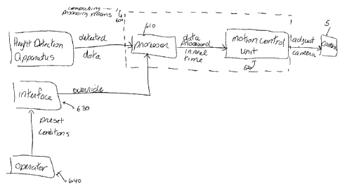
Referring to Figure 15, the present invention also includes a computer
processing
means 600, with processor 610 for processing the data received by the height
detection
apparatus and for controlling the automatic adjustment of the camera. The
height
detection information is processed in real time and fed to a motion control
unit 620 which
is capable of adjusting the position of the camera, thereby minimizing the
distance
between the camera and the patient. The scintillation camera 5 also includes
an interface
630 with on screen menus and function input means for selecting a variety of
scintillation
camera functions, including preset conditions for controlling the height of
the detector
head. The operator 640 may enter the preset conditions at interface 630, which
is fed to
motion control unit 620 which is capable of adjusting the camera to the
preferred height
or heights set.
While the invention has been described according to what is presently
considered
to be the most practical and preferred embodiments, it must be understood that
the
invention is not limited to the disclosed embodiments. Those ordinarily
skilled in the art
will understand that various modifications and equivalent structures and
functions may
be made without departing from the spirit and scope of the invention as
defined in the
claims. Therefore, the invention as defined in the claims must be accorded the
broadest
possible interpretation so as to encompass all such modifications and
equivalent
structures and functions.