Language selection

Search

Patent 2310620 Summary

Third-party information liability

Some of the information on this Web page has been provided by external sources. The Government of Canada is not responsible for the accuracy, reliability or currency of the information supplied by external sources. Users wishing to rely upon this information should consult directly with the source of the information. Content provided by external sources is not subject to official languages, privacy and accessibility requirements.

Claims and Abstract availability

Any discrepancies in the text and image of the Claims and Abstract are due to differing posting times. Text of the Claims and Abstract are posted:

  • At the time the application is open to public inspection;
  • At the time of issue of the patent (grant).
(12) Patent: (11) CA 2310620
(54) English Title: A FOOD CONTAINER
(54) French Title: RECIPIENT POUR ALIMENTS
Status: Deemed expired
Bibliographic Data
(51) International Patent Classification (IPC):
  • A47G 19/06 (2006.01)
  • B65D 21/02 (2006.01)
(72) Inventors :
  • FERRARO, DANIELA MONICA CATERINA (Italy)
(73) Owners :
  • PELLEGRINO & ASSOCIATI S.P.A. (Italy)
(71) Applicants :
  • FERRARO, DANIELA MONICA CATERINA (Italy)
(74) Agent: MACRAE & CO.
(74) Associate agent:
(45) Issued: 2007-09-11
(86) PCT Filing Date: 1998-11-25
(87) Open to Public Inspection: 1999-06-03
Examination requested: 2003-11-21
Availability of licence: N/A
(25) Language of filing: English

Patent Cooperation Treaty (PCT): Yes
(86) PCT Filing Number: PCT/EP1998/007615
(87) International Publication Number: WO1999/026847
(85) National Entry: 2000-05-18

(30) Application Priority Data:
Application No. Country/Territory Date
TO97A001033 Italy 1997-11-26

Abstracts

English Abstract


The food container (10) can be superimposed onto the upper
end of a beverage receptacle (12, 32, 34). It has a side wall (14) and
a bottom wall (16) in which there is formed at least one channel (18)
to allow the passage out through the container (10) of a drinking
straw (20) which penetrates into the receptacle (12, 32, 34). The
bottom wall (16) is provided with means for allowing connection of
the food container (10) to a receptacle (12, 32, 34) chosen from at
least two receptacles having different dimensions at the upper end.
Preferably such means allow a stable connection of the container
(10) to the receptacle (12, 32, 34), in particular one which is not
separated by the force of gravity alone.


French Abstract

Récipient pour aliments (10) pouvant être placé au-dessus de l'extrémité supérieure d'un réservoir à boissons (12, 32, 34). Ce récipient possède une paroi latérale (14) et une paroi inférieure (16) dans lesquelles se trouve au moins un passage (18) permettant à une paille (20) de traverser ledit récipient (10) et de pénétrer dans le réservoir à boissons (12, 32, 34). Sa paroi inférieure (16) comporte des moyens permettant d'accoupler ce récipient (10) à un réservoir (12, 32, 34) sélectionné dans au moins deux réservoirs dont l'extrémité supérieure possède des dimensions différentes. Ces moyens assurent, de préférence, un accouplement stable du récipient (10) et du réservoir (12, 32, 34), en particulier, un accouplement qui n'est pas séparé sous l'effet d'une seule force de gravité.

Claims

Note: Claims are shown in the official language in which they were submitted.


6

THE EMBODIMENTS OF THE INVENTION IN WHICH AN EXCLUSIVE PROPERTY
OR PRIVILEGE IS CLAIMED ARE DEFINED AS FOLLOWS:


1. A food container (10) superimposable over the upper end of
a beverage receptacle (12,32,34), said container (10) having a
side wall (14) and a bottom wall (16) in which there is formed at
least one channel (18) to allow the passage out through the
container (10) of a drinking straw (20) which extends into the
receptacle (12,32,34), said bottom wall (16) of said container
(10) being provided with means for selectively connecting the
container (10) to a receptacle (12,32,34) selected from at least
two receptacles having different dimensions at the upper end,
said connection means forming a stable connection of the
container (10) to the receptacle (12,32,34), which connection is
inseparable by the force of gravity alone, wherein said bottom
wall (16) has a cavity with a generally frusto-conical upwardly
tapered profile, in which there are formed at least two steps
(22) which extend circumferentially and which comprise a vertical
or riser part (24) and a horizontal part (26), wherein said riser
(24) has, at its lower end, a projection (28) forming an undercut
so as to allow engagement of the edge (30) of the upper end of
the receptacle (12,32,34) and its stable connection to the
container (10), and wherein the projection forming the undercut
is circumferentially continuous except for the presence of the at
least one channel.


2. A container (10) according to claim 1, wherein said bottom
wall (16) has three or more steps (22) formed therein.


7

3. A container (10) according to claim 1, wherein the side
walls (14) and bottom wall (16) of the container (10) have a
plurality of circumferentially off-set channels (18) formed
therein to allow the passage out through the container (10) of a
drinking straw (20) which penetrates into the receptacle
(12,32,34).

Description

Note: Descriptions are shown in the official language in which they were submitted.


CA 02310620 2000-05-18

WO 99/26847 PCT/EP98/07615
A food container

The present invention relates to a food container which can be
superimposed over the upper end of a beverage receptacle, and
to an assembly comprising the food container and the beverage
receptacle.

In more detail, such container has a side wall and a bottom
wall, in which is formed at least one channel to allow the
passage through the cover of a drinking straw which extends
into the beverage receptacle.

Containers of this general type are known, for example, from
prior art documents GB-A-2 023 407, FR-A-2 649 080 and FR-A-2
733 403. They allow a consumer to carry both solid foods and
drinks ready for consumption together using only one hand
without having recourse to difficult manipulations or external
supports.

Such containers are therefore particularly suitable for use in
fast food restaurants in which structures such as chairs and
tables which allow the user consume meals in a seated position
are not provided.

The above-mentioned known containers are made in such a way
that they can be associated with a single type of receptacle
having an upper end of well defined dimensions.

In practice, however, in an individual restaurant establishment
drinks are sold in various types of containers, for example
metal cans and cups of plastics material, which are decidedly
different from one another. Moreover even containers of the
same type can have very different capacities, varying for
example from 0.1 to 1 litre and therefore decidedly different
dimensions at the upper end.

This causes the disadvantages that the individual restaurant


CA 02310620 2000-05-18

WO 99/26847 PCT/EP98/07615
2

establishment must be provided with different types of
containers which can be associated with different receptacles
and which the staff must chose upon sale to select the
container suitable for accompanying the receptacle sold at any
one time.

For the purpose of obviating these disadvantages the object of
the present invention is a container and an assembly formed by
this latter and a receptacle associated with it, having the
characteristics indicated in the following claims.

An individual container according to the invention can be
associated with receptacle having different dimensions at the
upper end. This allows restaurants to hold stocks of
containers of only a single dimension with an evident saving in
storage costs. At the same time the operations of the staff
upon sale are speeded up since these latter do not have to
choose the size of the container to couple to a given
receptacle.

The container of the invention can be produced of any
conventional material, for example plastics or cardboard, with
the use of known technologies, for example thermo-forming.

Advantageously, the containers of the invention can be stacked
on one another so as to reduce the costs of transport and
storage.

Further advantages and characteristics of the present invention
will become apparent from the following detailed description,
given with the aid of the attached drawings and provided purely
by way of non-limitative example, in which:
Figure 1 is a perspective view from below of a container
according to the invention;
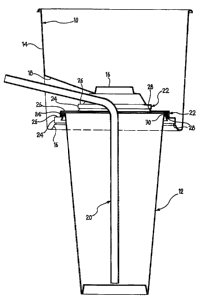
Figure 2 is side elevation of the container of Figure 1
associated with a receptacle; and
Figures 3 and 4 are side elevations of the container of


CA 02310620 2000-05-18

WO 99/26847 PCT/EP98/07615
3
Figure 1 associated with different receptacles.

A food container 10 which can be superimposed over the upper
end of a beverage receptacle, for example a cup 12 such as that
illustrated in Figure 2, has (Figures 1 and 2) a slightly
frusto-conical side wall 14 and a bottom wall 16.

In the walls 14, 16 there are formed a plurality of
circumferentially off-set channels 18 to allow the passage out
through the cover 10 of a drinking straw 20 which extends into
the receptacle 12.

The bottom wall 16 has a cavity with a generally upwardly
tapered frusto-conical profile, in which there are formed three
steps 22 which extend circumferentially and comprise a vertical
or riser part 24 and a horizontal part 26.

The riser 24 of each step 22 has, at its lower end, a
projection 28 to form an undercut.

On the outside of the side wall 14 there may be provided
decorations and/or advertising messages.

To fit the container 10 to the receptacle 12 the upper end of
this latter is pressed axially against the bottom wall 16 of
the container 10 until reaching a step 22 of dimensions
corresponding, for example, to that in an intermediate position
(see Figure 2).

The edge 30 of the upper end, which projects radially with
respect to the body of the container, causes a slight elastic
divergence of the projection 28 from the riser 24 of this step
22, which, upon further movement in an axial direction of the
receptacle 12, returns into its original position lying
alongside the edge 30. Alternatively, depending on the
relative rigidity of the projection 28 and the edge 30, it is
possible that this latter may be subject to a slight elastic


CA 02310620 2000-05-18

WO 99/26847 PCT/EP98/07615
4

contraction following the axial movement of the drinks
container 12.

In either case a stable connection of the receptacle 12 to the
container 10 is produced, in particular one which cannot be
separated by the effect of the force of gravity alone, thus
allowing a secure manipulation of the assembly constituted by
these two elements.

Subsequently the drinking straw 20 is introduced into one of
the channels 18, which straw can thus penetrate into the
receptacle 12 dipping into the liquid contained in it and
making it accessible to a consumer.

Solid foods contained in the container 10 are on the other hand
directly accessible through the upper opening of this latter.
The assembly formed by the container 10 and the receptacle 12
therefore allows the user to carry both the solid foods held in
the container 10 and the drinks held in the receptacle 12 both
together using only one hand, both ready for consumption
without having recourse to difficult manipulations or external
supports.

Obviously, whenever it is desired to connect the container 10
to a receptacle of different dimensions the same operations as
those described above would be effected with the difference
that the edge of the receptacle would become engaged by a
different step 22 of the bottom wall 16. This can be seen by
way of example in Figures 3 and 4, in which the container 10 is
respectively connected to a cup 32 of greater dimensions than
that illustrated in Figure 2, and a can 34.

Generally, therefore, the steps 22 serve as means able to allow
the connection of the container 10 to receptacles 12, 32, 34
having different dimensions at the upper end.


CA 02310620 2000-05-18

WO 99/26847 PCT/EP98/07615

Naturally, it is intended that, the principle of the invention
remaining the same, the details of construction and the
embodiments can be widely varied with respect to what has been
described and illustrated in the drawings, without by this
departing from the ambit of the present invention.

For example, in the bottom wall 16 of the container 10 there
may, in principle, be provided any number of steps 22 so as to
allow coupling with a corresponding number of receptacles
having upper ends of different dimensions. These steps can
moreover have a plan form other than circular, for example
rectangular or square, to allow coupling with a receptacle, for
example, of parallelepiped form.

Representative Drawing
A single figure which represents the drawing illustrating the invention.
Administrative Status

For a clearer understanding of the status of the application/patent presented on this page, the site Disclaimer , as well as the definitions for Patent , Administrative Status , Maintenance Fee  and Payment History  should be consulted.

Administrative Status

Title Date
Forecasted Issue Date 2007-09-11
(86) PCT Filing Date 1998-11-25
(87) PCT Publication Date 1999-06-03
(85) National Entry 2000-05-18
Examination Requested 2003-11-21
(45) Issued 2007-09-11
Deemed Expired 2010-11-25

Abandonment History

There is no abandonment history.

Payment History

Fee Type Anniversary Year Due Date Amount Paid Paid Date
Application Fee $150.00 2000-05-18
Maintenance Fee - Application - New Act 2 2000-11-27 $50.00 2000-09-27
Maintenance Fee - Application - New Act 3 2001-11-26 $50.00 2001-09-27
Maintenance Fee - Application - New Act 4 2002-11-25 $100.00 2002-11-25
Maintenance Fee - Application - New Act 5 2003-11-25 $150.00 2003-10-02
Request for Examination $400.00 2003-11-21
Registration of a document - section 124 $100.00 2004-01-14
Maintenance Fee - Application - New Act 6 2004-11-25 $200.00 2004-09-28
Maintenance Fee - Application - New Act 7 2005-11-25 $200.00 2005-09-28
Maintenance Fee - Application - New Act 8 2006-11-27 $200.00 2006-09-26
Final Fee $300.00 2007-06-18
Maintenance Fee - Patent - New Act 9 2007-11-26 $400.00 2008-06-17
Maintenance Fee - Patent - New Act 10 2008-11-25 $125.00 2008-10-17
Owners on Record

Note: Records showing the ownership history in alphabetical order.

Current Owners on Record
PELLEGRINO & ASSOCIATI S.P.A.
Past Owners on Record
FERRARO, DANIELA MONICA CATERINA
Past Owners that do not appear in the "Owners on Record" listing will appear in other documentation within the application.
Documents

To view selected files, please enter reCAPTCHA code :


To view images, click a link in the Document Description column. To download the documents, select one or more checkboxes in the first column and then click the "Download Selected in PDF format (Zip Archive)" or the "Download Selected as Single PDF" button.

List of published and non-published patent-specific documents on the CPD .

If you have any difficulty accessing content, you can call the Client Service Centre at 1-866-997-1936 or send them an e-mail at CIPO Client Service Centre.


Document
Description 
Date
(yyyy-mm-dd) 
Number of pages   Size of Image (KB) 
Cover Page 2007-08-14 2 40
Drawings 2000-05-18 4 75
Description 2000-05-18 5 205
Abstract 2000-05-18 1 51
Claims 2000-05-18 2 70
Representative Drawing 2000-08-04 1 7
Cover Page 2000-08-04 2 55
Claims 2006-09-29 2 49
Representative Drawing 2007-06-11 1 5
Assignment 2000-05-18 3 90
PCT 2000-05-18 6 188
Fees 2002-11-25 1 27
Prosecution-Amendment 2003-11-21 1 28
Assignment 2004-01-14 2 60
Prosecution-Amendment 2004-05-19 1 33
Prosecution-Amendment 2006-03-31 4 109
Prosecution-Amendment 2006-09-29 6 265
Correspondence 2007-06-18 1 30