Note: Descriptions are shown in the official language in which they were submitted.
CA 02311212 2000-06-12
FIELD OF THE INVENTION
The invention relates to an improved mounting clip for use in combination with
locking mechanisms for office furniture, cabinets and other storage
compartments. In
particular, the clip may be used to secure locking core housings within
cabinets and
s other storage compartments. The invention also relates to certain
improvements
provided in the locking housing.
BACKGROUND OF THE INVENTION
Locking mechanisms are commonly used to secure storage compartments in
office furniture including desks, cabinets, credenzas and other storage
facilities.
to Conventional locking mechanisms have been used with storage facilities
including, in
some instances, anti-tip features designed to prevent cabinets and other
storage units
from tipping over accidentally if multiple drawers are allowed to open
simultaneously.
For example, US patent numbers 4,936,640, 5,056,877 and 5,062,678 show several
examples of anti-tip mechanisms used in prior locking cabinet systems. Prior
locking
is storage systems have used rotating conventional locking core systems.
An example of an earlier locking core system is described in US patent number
5,109,685. The noted reference shows an example of a removable locking core
with a
housing that is mounted on a cabinet drawer by exterior mounting screws. In
other
systems, locking apparatuses have been mounted by using conventional clips
that must
2o be attached from a position within the interior of the storage unit. During
installation, the
installer must securely hold the locking apparatus in place in the storage
unit while
1
CA 02311212 2000-06-12
trying to secure the mounting clip to the locking assembly portion positioned
within the
interior of the locking storage unit.
In some instances, locking core housings have been provided with retainer
springs that may be installed through an opening in the front wall of drawer,
cabinet or
other installation site. US patent 5,435,159 to Ramsauer discloses a complex
retainer
spring that is secured to a cylindrical lock housing by means of a bolt, screw
or rivet. In
some instances, the retainer spring may be installed prior to installation of
the locking
apparatus (assembly) in the locking compartment. However, the use of such a
clip
requires additional manufacturing steps in making the spring and additional
means to
to secure the spring to the locking core housing. For example, if screws are
used to
secure the spring to the housing, suitable preformed openings must be provided
in the
housing to receive the screws. In other instances, threaded openings may also
be
necessary for this purpose. Where screws and bolts are used, for example, the
housing
must be adequately reinforced to receive and hold the screws or bolts securely
after
Is installation. Again, such features will add to the overall cost and effort
required to
manufacture and assemble the components.
In other instances, other special features may be required on the springs or
on the
housing in order to permit suitable fastening of the spring to the housing.
Many of these
features will add significant costs to the overall cost of making and
installing the locking
2o assembly units. Where certain added features require low tolerances in
manufacturing
and assembly, total costs are typically increased for those locking
assemblies.
US patent 3,190,092 to Patriquin refers to a unitary cylindrical housing that
is molded
from plastic. Patriquin discloses a front mounting cylindrical housing with
integral
2
CA 02311212 2000-06-12
retainers used to secure the locking assembly in place. However, the
cylindrical
housing in Patriquin is practically limited to installations that will permit
use of plastic
housings. Many installations require assemblies manufactured from other
materials.
The physical characteristics and properties of isotropic materials such as
plastics used
s throughout the unitary housing in this reference may not be suitable for
certain
applications.
DISCLOSURE OF THE INVENTION
The present invention relates to a mounting clip that may be secured to a
locking core
housing without necessarily using welds, rivets, screws or bolts to hold the
clip in place
to after installation. The improved mounting clip may be attached to the
housing at the
installation site or away from the installation site, if desired. Special
tools are not
required in typical installations. Similarly, if required, the clip of the
present invention
may be promptly detached from a locking core housing in those instances where
the
locking core assembly is in need of repair or other service. For example, it
may be
is necessary to remove the entire locking core assembly from the storage
compartment.
The improved clip may be removed by prying or sliding the clip from the side
of the
housing.
By comparison, conventional systems in the prior art often require special
tools to
permit removal of conventional retainers or springs, or in some cases,
considerable
2o physical effort and time are required to remove the retainers or springs
from
conventional housings.
In one aspect of the invention, the improved mounting clip comprises an
arcuate band
or member. The arcuate member is configured to generally conform with a
3
CA 02311212 2000-06-12
corresponding outer portion of the lock housing and is generally made of
flexible,
resilient material to clamp or grasp the housing. Typically, the housing is
cylindrical or
elongate in shape and has a longitudinal axis. The overall configuration of
the arcuate
portion of the clip substantially conforms with the corresponding outer
portion of the lock
housing to provide for a snug fit. The arcuate member is configured to snap
into place,
grasping the housing, circumferentially about the longitudinal axis.
The improved clip may be provided with one or more retaining arms, extending
parallel
to the longitudinal axis. A retaining arm comprises a biased end portion,
projecting
outwardly from the longitudinal axis. The biased end portion is flexible and
resilient to
to permit temporary compression of the end portion during installation of a
locking core
assembly. The terminal portion of the retaining arm may be provided with an
inwardly
projecting flange. The flange may be provided to further inhibit the
accidental or
unauthorized removal of an installed locking core assembly from a storage
compartment. In addition, the flange provides for a secure, snug fit of the
assembly,
is including the housing, within the storage compartment wall.
In other embodiments, two or more retaining arms may be provided on a mounting
clip
of the present invention. In some embodiments, mounting clips may be
configured so
that only one mounting clip may be used per lock housing. In other
embodiments, the
mounting clips may be configured so that two mounting clips may be secured to
a lock
2o housing at the same time. The two clips may be identical, if that is
desired. In other
embodiments, it may be desirable to provide more than two clips on each
housing,
although some of the clips may be configured for placement at different
locations along
the length of the longitudinal axis.
4
CA 02311212 2000-06-12
In yet another embodiment of the invention, the improved mounting clip defines
a
longitudinal axis. The clip includes an arcuate portion that extends radially
about the
longitudinal axis. The mounting clip comprises at least one elongate body
extending
from the arcuate portion, parallel to the longitudinal axis. The elongate body
comprises
s a first arm portion that extends outwardly away from the longitudinal axis
when it is in
the second position. The first arm portion is spring-like and is adapted to
operate
between a first compressed position and a second extended position. The first
arm
portion of the elongate body has an abutting end or flange projecting inwardly
toward
the longitudinal axis.
io In yet another embodiment of the present invention, an improved locking
assembly is
provided. The assembly may be used in securing locking cores in furniture,
cabinets
and other structures including storage compartments. The assembly comprises a
lock
housing and a mounting clip. The assembly may be inserted into a corresponding
receptacle, such as an opening in an exterior wall of the storage compartment.
The
is lock housing and mounting clip are configured so that the clip may be
secured to the
housing outside of the storage compartment. Thereafter, the assembled housing
and
clip may be inserted together into the corresponding receptacle. While passing
into the
receptacle, the first spring-like portion of the clip is compressed into the
first position.
Once the assembly has been fully inserted, the first portion returns to the
second
2o position. The flange provided on the first portion abuts against the inner
wall of the
storage compartment to prevent withdrawal of the locking core assembly. The
flange
portion of the clip is configured to fit snugly up against the inner wall. The
assembly,
once installed into the storage compartment, cannot be accidentally removed
from the
CA 02311212 2000-06-12
receptacle. The assembly may be removed by depressing the first portion to the
first
position and then withdrawing the assembly from the receptacle. Alternatively,
the
storage compartment may be opened and the clip may be removed from the housing
while the assembly is inside the receptacle. In this second instance, once the
clip is
s removed, the housing may be withdrawn from the receptacle.
BRIEF DESCRIPTION OF THE DRAWINGS
The following drawings are included to illustrate several examples of
embodiments of
the present invention.
FIG. 1 is an exploded side view, in partial section, of an embodiment of a
locking
to mechanism, including a key, lock housing, mounting clip and driver
installed in a
compartment wall;
FIG. 1A is a perspective view of one embodiment of a mounting clip of the
present
invention;
FIG. 2A is a plan view of the mounting clip shown in FIG. 1A;
is FIG. 2B is a plan view of the mounting clip of FIG. 1A together with a lock
housing;
FIG. 2C is an elevation of the embodiment shown in FIGs. 2A and 2B;
FIG. 2 is a sectional view along line 2-2 in FIG. 2C;
FIG. 3A is a plan view of another embodiment of a mounting clip of the present
invention;
2o FIG. 3B is a plan view of the mounting clips of FIG. 3A together with a
lock housing;
FIG. 3C is an elevation of the embodiment shown in FIGs. 3A and 3B;
6
CA 02311212 2000-06-12
FIG. 3 is a sectional view along line 3-3 in FIG. 3C;
FIG. 4A is a plan view of another embodiment of a mounting clip of the present
invention;
FIG. 4B is a plan view of the mounting clip of FIG. 4A together with a lock
housing;
s FIG. 4C is an elevation of the embodiment shown in FIGs. 4A and 4B;
FIG. 4 is a sectional view along line 4-4 in FIG. 4C;
FIG. 5 is a perspective view of another embodiment of a mounting clip of the
present
invention; and
FIG. 5A is an elevational view of a partial section of a lock assembly of the
present
to invention.
DETAILED DESCRIPTION OF PREFERRED EMBODIMENTS
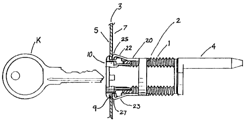
Figures 1 and 1A show a preferred embodiment of the present invention. A
locking core
assembly 2 is shown in partial sectional view. In particular, the assembly 2
is shown
installed in the outer wall 3 of a storage compartment. The locking core
assembly
is includes an elongated lock housing 1 that is generally cylindrical in
shape. It will be
understood in the art that the overall shape of the removable lock housings
may vary
according to the particular applications under consideration. In many
instances, the
lock housing may have exterior threading, flats and other precast features
intended for
use in particular applications, but not in others. In general, the overall
shape of the
2o housing will define a longitudinal axis. In the particular embodiment shown
in Figures 1
and 1A, a driver 4 is secured to a rotatable locking core mechanism (not
shown) located
within the housing 2. The core rotates about the longitudinal axis. A key K is
inserted
7
CA 02311212 2000-06-12
into a key slot (not shown) in the face plate 10 of the locking core (not
shown). The key
K may be used to rotate the locking core, to in turn activate the driver 4.
The assembly
includes a mounting clip 20 of the present invention. The mounting clip 20
includes an
arcuate band 30 that is generally C shaped. The arcuate band 30 extends
radially
s about an axis that generally coincides with the longitudinal axis of the
lock housing 1.
The arcuate band may be made of a suitable, flexible and resilient material
that will
allow the band to clamp on to the exterior of the lock housing 1. Again, it
will be
understood by those skilled in the art that there may be variations in shape
that will not
affect the efficacy of the invention. However, it is preferred that the
arcuate band 30 be
io configured to closely follow the contour of the corresponding exterior
surface of the lock
housing 1. If the lock housing is irregularly shaped, with for example flats
or edges, the
band 30 may be shaped in a similar manner to better engage the housing 1 to
resist
displacement of the clip 20 from the housing 1 after installation.
The illustrated embodiment has upper arm 40 and lower arm 50. The upper and
lower
is arms 40, 50 extend from the ends of the arcuate band 30, parallel to the
longitudinal
axis. Upper arm 40 includes an upper spring section 22 that under normal
circumstances projects outwardly from the longitudinal axis. The terminal
portion of
upper spring section 22 ends in a flange 25. Similarly, flange 27 forms the
terminal
portion of lower spring section 23. In the preferred embodiment, the clip 20
may be
2o stamped or otherwise manufactured as a single piece, from a_sheet of
suitable material.
The assembly 2 is shown in the installed position, interior of a storage
compartment.
When installed, upper and lower spring sections 22, 23 are extended toward
their
normal positions. Corresponding flange portions 25, 27 engage with the inner
wall
8
CA 02311212 2000-06-12
surface 7 of the exterior compartment wall 3 to hold the housing firmly in
place, within
the receptacle or opening 9 in the wall 3.
During installation, the lock housing 1 and the mounting clamp are inserted
together
from the exterior of the compartment structure to the interior through opening
9. (With
s reference to Figure 1, this installation step corresponds to movement from
left to right,
through the opening 9, and into the interior of the compartment.)
During installation, upper and lower spring sections 22 and 23 are compressed
when
passing through opening 9. When the spring sections 22 and 23 are fully
compressed,
there is sufficient clearance within the opening 9 to permit the mounting clip
and
io housing to pass through the opening 9. After passing through the opening,
the spring
sections 22 and 23 return to their normally extended positions. Terminal
flange portions
25, 27 snugly engage the inner wall 7 of the compartment. The terminal flange
portions
25, 27 extend outwardly beyond the perimeter of the opening 9 to engage the
inner wall
and prevent withdrawal of the assembly from the locking compartment.
is In the preferred embodiment of the present invention, the housing 1 is
provided with a
channel for receiving the arcuate band 30. With reference to Figures 2B and
2C, lateral
channel 270 is of sufficient dimensions to receive arcuate clamp member 30.
The
channel 270 is positioned to place the mounting clip at an ideal distance from
the inner
wail surface of wall 3. Longitudinal channel 260 is also provided to receive
the lower
2o arm portion 41 of clip 20. Edge 61 and extension edge 62 engage with a
corresponding
channel wall of channel 260 when the clip is installed into its desired
position. The clip
is configured of resilient, flexible material with portions 41,30 that
correspond to the
9
CA 02311212 2000-06-12
contours of channels 260, 270. The clip portions 41, 30 snap into position
when the clip
20 is installed.
It is possible to use other features to retain the clip in a desirable
position on the
housing. For example, in some embodiments, a rim or other raised posts or
elements
s (not shown) may be used to limit longitudinal displacement of the clip along
the housing
during installation or later operation. Channels having dimensions
corresponding to the
dimensions of the clip (as exemplified by channels 260 and 270) are preferred.
The
placement of the arcuate member within the corresponding channel reduces the
clearance necessary for the installed clip 20 when it is inserted through the
opening 9
io during installation along with the housing 1. In many instances it will be
relatively
inexpensive and convenient to form the desired channels 260, 270 when
manufacturing
the housing. For example, where the housing is made of die cast metal, the
channel
may be included with little inconvenience or cost.
With reference to Figures 2A, 2B, 2C, and 2, the mounting clip 20 shown in
Figures 1
is and 1A is shown installed on a housing 1. In Figure 2, the sectional view
illustrates the
outward projection of upper and lower spring sections 22 and 23 when the
mounting clip
20 is installed.
With reference to Figures 3A, 3B, 3C, and 3, a pair of mounting clips 320 and
320'are
mounted on housing 13. Clip 320 has an arcuate clamping portion 331 which
nests
2o within a portion of channel 370. Channel 370 extends about the housing 13
to receive
clamping portions 331 and 332 of clips 320 and 320' respectively. The clips
320 and
320' include respective spring portions 301 and 301'. In Figure 3C, flange
portion 325
CA 02311212 2000-06-12
of spring 301' and flange 327 of lower spring 311' are shown in contact with
the inner
surface of wall 3 of the storage compartment.
Although Figures 3A, 3B, 3C, and 3 show a pair of clips each having upper and
lower
spring portions, other configurations and embodiments may be desirable. For
example,
s in some instances, it may be desirable to have only one spring arm provided
on a
mounting clip. In some embodiments, the spring arm may be located at an
intermediate
point along the corresponding arcuate clamping member.
Figures 4A, 4B, 4C, and 4 show yet another embodiment of the mounting clip of
the
present invention. Mounting clip 420 is shown installed in a corresponding
channel 470
io provided on the corresponding housing 14. The clip 420 is provided with a
mounting
clamp member 430 which nests within channel 470. The clamp member is
preferably
made of a flexible, resilient material and configured to firmly grip about the
outer
perimeter of the housing. The channel and clamp member may also be configured
to
inhibit accidental lateral displacement of the mounting clip from the housing
during
is installation or subsequent operation.
In this embodiment, upper arm 440 and lower arm 450 are provided with elbow
segments 445 and 455 respectively. In some applications, the available
clamping
position (corresponding to the position of channel 470) may be located
relatively close
to the wall 3. In those instances, it may desirable to extend the relative
length of the
2o upper and lower arms 440 and 450 by providing corresponding elbow elements
445 and
455. Spring portions 422, 423 are provided with respective flanges 425 and
427. The
flanges 425 and 427 fit snugly against wall 3 to hold the housing assembly in
place after
installation.
11
CA 02311212 2000-06-12
In the preferred embodiment shown in Figures 1 and 1A, and particularly in
those
instances where the clip 20 is made from a relatively thin band, the flanges
25, 27
provide added resistance to longitudinal movement of the housing after
installation. The
flange may be used as an added spring element. Flange segments 26 and 28 may
be
s manufactured so that they are sloped at an angle to the vertical wall 3 in
their
uninstalled condition. Following installation on the housing 1 and insertion
into the
storage compartment, the flange segments 26 and 28 are deflected during the
movement of the spring portions 22, 23 outwardly from the longitudinal axis.
The flange
elements engage with the surface of the inner wall to provide added resistance
against
to longitudinal movement of the housing outward through the opening 9. Flange
segments
26, 28 may even be scored or textured to better engage the inner surface of
wall 3.
Figures 5 and 5A show another embodiment of the mounting clip. Mounting clip
520 is
made from a single, stamped or like formed material. The clip 520 is provided
with an
arm 540 and a spring portion 522 of sufficient length to engage the inner wall
surface of
is the storage compartment. The spring portion terminates in a flange portion
525. The
flange 525 has an engagement surface 526 which contacts the inner wall
surface. The
clip 520 is mounted on the housing 501 by engagement in a channel 570 formed
between terminal edge 572 of the housing and adjacent end wall 571 of the
driver 504.
The clip 520 is also provided with flanges 575, 575' which engage with
longitudinal
2o corresponding channel segments 577. The flanges 575, 575' and corresponding
channel segments 577 are configured to allow the clip 501 to be snapped into
position
during installation. The legs 530, 530' are generally S-shaped when viewed in
profile,
providing scalloped portions S, S' and bend portions 532, 532' which may be
used to
12
CA 02311212 2000-06-12
act as a washer between the housing 501 and the driver 504. The legs 530, 530'
may
also be shaped by bending or other means to provide a tensioning washer
between the
housing 501 and driver 504, to enhance the operation of the driver.
In some instances, it may not be necessary to provide flanges on the spring
portions.
s For example, the thickness or configuration of a spring arm may be such that
an
adequate contact area (to impact against the compartment wall) is presented by
the
terminal end of the spring portion itself. In other embodiments, the terminal
ends of the
spring portions may be configured in other ways to improve contact between the
wall
and the terminal ends of the spring arms.
io The mounting clip of the present invention may be manufactured from a
variety of
flexibly resilient materials having physical characteristics adequate for the
intended
applications. In some instances, treated metals or alloys may be used. In some
instances, suitable plastics may be employed.
It is also to be understood that the spring arms may be configured in a manner
that will
is permit them to be compressed against the housing in certain circumstances,
to permit
removal of the housing and the clip from the compartment without having to
first unlock
or open the compartment. For example, the face plate 10 may be adapted so that
it can
be removed along with the locking core. Master keys are often used to extract
removable locking cores. The face plate may also be designed for removal after
the
20 locking core is removed. Once the face plate is removed, a tool such as
pliers or similar
clamping tool may be inserted into the compartment interior through the
opening 9. If
necessary, additional clearance may be provided in the wall, or specially
designed
access channels may be provided in the wall 3 to limit access to special tools
only.
13
CA 02311212 2000-06-12
Thereafter, the appropriate tool may be used to engage the ends of arms 22 and
23 and
compress them so that the housing and clamp may be withdrawn back through the
opening without first opening the compartment.
Further embodiments and modifications of the mounting clip and housing
assemblies
described herein will occur to those skilled in the art and such modifications
and
embodiments are intended to be covered by the following claims.
14