Note: Descriptions are shown in the official language in which they were submitted.
CA 02311312 2000-OS-23
TITLE: REMOVEABLE END COVER FOR CYLINDER, SHAPED
FOOD ROLLS
FIELD OF THE INVENTION
The present invention relates to covers for food items.
More particularly, the present invention relates to a
reusable cover that can be placed on the end of a food roll
for the purpose of displaying advertising indicia, and or
for covering the end of the food roll after it has been
opened.
BACKGROUND OF THE INVENTION
A number of food items are packaged and sold in
cylinder shaped rolls, including raw or cooked sausage and
other meats, cookie dough, and the like. The dimensions of
food rolls can vary from one product to the next, but
regardless of these dimensional variations, most food rolls,
when sold, will have a uniform circular cross sect ion over
most of their length and rounded or tapered ends.
Food rolls are usually encased in unitary, th row-away
plastic packages. The external surface of a food roll
1
CA 02311312 2000-OS-23
package generally displays information pertaining to the
maker of the food product, ingredients of the food product,
expiration or freshness dates, etc. However, the rounded
ends of food rolls are generally not well suited for
displaying such information, or other information such as
advertising and marketing indicia. Consequently, a need
exists for a device that can be used on the ends of food
rolls for displaying information.
Food rolls often come in packages that contain more
food material than will be consumed at one time. The buyer
of such a food roll will usually cut off a portion of the
food roll for immediate use, and save the remainder of the
food roll for later use. The saved portion of the food roll
is left with an open end that exposes the food item in the
food roll to the environment outside of the package. These.
packages generally do not include a closure means that can
be used to seal off and protect the exposed end of the food
roll, so the consumer must provide his or her own means for
sealing the end of the food roll, such as aluminum foil or
plastic wraps that are commonly available in grocery stores.
The use of such items on a repetitive basis may be
undesirable to many people, who would prefer to accomplish
this task by means of a reusable cover.
From the foregoing, it is seen that a need exists for a
reusable cover that can be installed onto the ends of food
rolls, for the purpose of displaying information such as
marketing and advertising indicia, and or for the purpose of
minimizing the exposure of an opened end of a food roll to
the environment.
2
CA 02311312 2000-OS-23
SUMMARY OF THE INVENTION
The present invention provides an end cover that can be
detachably connected to both the opened and unopened end of
a cylindrical food roll of a predetermined size, including a
predetermined food roll diameter, for the purpose of
displaying information at an end of the food roll and for
limiting the exposure of an opened end of the food roll to
the environment.
The end cover includes an end plate with an external
side adapted to display information such as marketing
indicia, an internal side, and a thickness therebetween. A
retaining member having a proximate end connected to the end
plate extends away from the internal side to a distal entry
end that is adapted to receive an end of the food roll.
The retaining member has an inside surface that
provides an internal volume with a volume length and a
substantially uniform cross section area that is sufficient
to accommodate at least a portion of the length of the food
roll. At least one gripping surface is positioned on the
inside surface to resiliently bear against and apply force
to an external surface of the food roll, and the retaining
member has at least one other surface adapted to apply force
to an external surface of the food roll, when the food roll
is inserted into the volume through the distal entry end.
According to another aspect of the invention, the end
plate includes an indicia surface that is recessed within
the thickness of the end plate an inset distance from the
external side.
According to another aspect of the invention, a label
adapted to display advertising information is connected to
the indicia surface, and the label has a thickness that is
less than the inset distance.
3
CA 02311312 2000-OS-23
According to another aspect of the invention, the
retaining member comprises a tubular portion at the
proximate end, that has a tube length extending from said
proximate end towards said distal entry end.
According to another aspect of the invention, the
retaining member comprises one or more resilient beam
members extending from the tubular portion towards the
distal entry end, and a gripping surface is positioned on
each beam member to resiliently bear against an external
surface of the food roll to bias the food roll into contact
with a portion of the inside surface found on said tubular
portion.
According to another aspect of the invention, the beam
members are evenly spaced on a circumference of the
retaining member.
According to another aspect of the invention, the
resilient beam members each include a gripping member with a
gripping surface found thereon that extends from the beam
members towards a central axis of the end cover. The
gripping surfaces are positioned on a gripping circumference
with a gripping diameter that is less than the predetermined
diameter of the food roll, so that when the end cover is
installed upon an end of the food roll, the gripping
surfaces resiliently bear against an external surface of the
food roll to retain the end cover on the food roll.
According to another aspect of the invention, at least
one of the gripping members has a forward sloped surface
extending from the beam member to the gripping surface, that
faces the distal entry end of the retaining member.
According to another aspect of the invention, at least
one of the gripping members has at least two sloped surfaces
extending from the resilient beam member to the~gripping
surface.
4
CA 02311312 2000-OS-23
According to another aspect of the invention, the
retaining member comprises a unitary elastic sleeve, having
an inside surface with a relaxed, substantially uniform
diameter that is less than the predetermined diameter of the
food roll, and that is elastically expandable to at least
the predetermined diameter of the food roll, so that when
the elastic sleeve is placed over an end of the food roll,
the inside surface encircles at least a portion of a length
of the food roll and applies force to an external surface of
the food roll to retain the end cover on the food roll.
According to another aspect of the invention, the
distal entry end of said elastic sleeve terminates in a
lip.
BRIEF DESCRIPTION OF THE DRAWINGS
Figure 1 is a side elevation of a first embodiment end
cover shown in section view, and a view of a food roll with
an opened arid an unopened end.
Figure 2 is an end view of the end cover embodiment
shown in Figure 1.
Figure 3 is an enlarged detail view of a gripping
surface for the end cover.
Figure 4 is a side elevation view of an alternative
embodiment end cover, shown in partial section view,
installed on an unopened end of a food roll.
Figure 5 is a perspective view of the end cover
embodiment shown in Figure 1, partially broken away,
installed on an opened end of a food roll.
DETAILED DESCRIPTION OF A PREFERRED EMBODIMENT
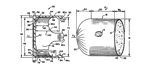
FIGURE 1 shows a cylindrical food roll ( 10 ) . The food
roll includes a unitary throw-away package (12) made from a
5
CA 02311312 2000-OS-23
plastic or other suitable material that is filled with a
food item (14) ,such as sausage, other types of meats, cookie
dough, or the like.
The package has an external surface (16) and a
substantially uniform, predetermined diameter (18) over a
major length portion (20). End (22) is rounded, with a
predetermined length (24) and is typical of the end
configuration of a food roll as it is sold in grocery
stores. End (26) is shown in a configuration where a portion
of the food roll and package have been cut off and removed
by the consumer, leaving a portion (28) of the food item
exposed to the environment. The cut or opened end (26) of
the food roll will usually have a length (29), since most
consumers will not cut the food roll at a precise right
angle to the central axis F1 of the food roll. Such length
will of course vary from one opened end to the next,.
depending upon how the food roll is cut by the consumer.
An end cover (30) adapted for detachable engagement
with both the opened and unopened end of a food roll is
shown in Fig. 1. It is to be understood that the end covers
described herein are not limited to a particular size, and
that their dimensions can vary as needed to accommodate a
food roll of a predetermined size and diameter. The end
cover (30) illustrated in Figure 1 is preferably a unitary
item made from high density polyethylene, and may also be
made from a polypropylene homopolymer material.
The end cover includes an end plate (32) and a
retaining member (34). The end plate (32) has a
circumference surface (36), an external side (38) adapted to
display information, an internal side (40), and a thickness
(42) .
The end plate (32) includes an indicia .surface (44)
that displays advertising or other types of information (not
6
CA 02311312 2000-OS-23
shown). The indicia surface is preferably, but not
necessarily, recessed into the thickness (42) by an inset
distance (46) as measured from the external side. The
indicia surface has a diameter (48) that is less than the
diameter (50) of the end plate. The respective diameters
(50) and (48) of the end plate and indicia surface are
selected as desired to provide a bead (52) with a shield
surface (54) on the external side (38) adjacent the
circumference surface (36).
An adhesive backed label (56) having a thickness (58),
and bearing information such as marketing or advertising
indicia (not shown), is connected to the indicia surface
(44).- The label thickness (58) can be less than the inset
distance (46), and if so, the label (56) will lie completely
within the thickness (42) of the end plate (32) and not
protrude beyond the shield surface portion (54) of external
side (38). Consequently, any such labels will be shielded
to some extent from damage during handling, packaging,
shipment, etc, by the shield surface (54).
Retaining member (34) has a proximate end (60)
connected to the end plate (32), and extends away from the
internal side (40) to a distal entry end (62) that is
adapted to receive ends (22) and (26) of the food roll. The
retaining member includes an external surface (64), a wall
thickness (66), and an inside surface (68). As seen in Fig.
2, the inside surface (68) has an internal diameter (70) and
a circular cross section area (71). Diameter (70) is
selected to be slightly larger than the diameter (18) of
food roll (10). The inside surface (68) has a length
portion (72) that, together with the circular cross section
area (71), provides an internal (74) volume within the
retaining member sufficient to accommodate a desire d length
of the food roll.
7
CA 02311312 2000-OS-23
The proximate end (60) includes a tubular portion (76)
that is connected by radiused corner (78) to the internal
side (40) of the end plate (32). The tubular portion has a
tube length (80) extending from the internal side (40)
partway towards the distal entry end (62) to rounded tube
ends (82a), (82b), (82c), and (82d). Each of rounded tube
ends include a chamfered surface (84a), (84b), (84c), and
(84d) that slopes inward towards the central longitudinal
axis L1 of the end cover (30), with the degree of the chamfer
preferably being 45 degrees. Providing a chamfer on these
edges can facilitate the installation of the end cover onto
a food roll by minimizing the possibility of snags between
the food roll and rounded ends (82a), (82b), (82c) and
( 82d) .
Resilient beam members (90), (92), (94) and (96) are
connected to and extend away from the rounded tube ends
(82a), (82b), (82c), and (82d), towards the distal entry end
(62). The resilient beam members terminate at flat tip
surfaces (90a), (92a), (94a) and (96a). The resilient beam
members include gripping members (100), (102), (104), and
(106) that extend from the inside surface (68) towards
central axis L1.
The construction of gripping member (100) is shown in
greater detail in Figure 3, and is typical of the
construction of the other gripping members (102), (104) and
(106). Gripping member (100) includes a forward sloped
surface (107) facing the distal entry end (62) and a reverse
sloped surface (110) facing the end plate (32). The
similarly constructed gripping members (102), (104) and
(106) have forward sloping surfaces (109) , (111) and (113)
respectively. The forward and reverse sloped surfaces are
positioned at angles ml and o2 with respect to ihside surface
(68), and in the preferred embodiment, the angles ral and sae
8
CA 02311312 2000-OS-23
are each thirty degrees. The forward sloped surface (107)
extends into the flat tip surface (90a), which has a
thickness (112) that is less than the wall thickness (66) of
the retaining member (34).
The forward and reverse sloped surfaces (108) and (110)
meet at gripping surface (120). Referring to Figure 2, the
gripping surfaces (120) , (122), (124), and (126) are shown
positioned along a gripping circumference (128) having a
gripping diameter (130), which is selected to be slightly
less than the diameter ( 18 ) of the food roll ( 10 ) . As seen
in Figure 2, sides (134) and (136) of gripping member (100)
are sloped, and the degree of the slope may be selected as
desired to vary the size of gripping surface (120). The
other gripping members (102, (104) and (106 may also be
provided with sloped side surfaces.
The gripping surfaces (120), (122), (124), and (126)
are positioned a distance (140) from internal side (40) of
end plate (32). Distance (140) is selected to ensure that
the gripping surfaces will be positioned on and resiliently
bear against the major length portion (20) of the food roll
(10) when the end cover is fully installed onto unopened end
(22) of the food roll. In other words, distance (140) will
be longer than the predetermined length (24) of the rounded
end (22) of the food roll on which the cap will be used.
Beam members (90), (92), (94), and (96) are evenly
spaced at 90° along the circumference (128) of the retaining
member (34), which evenly spaces the gripping surfaces
(120), (122), (124), and (126) along the gripping
circumference (128). One skilled in the art will recognize
that the retaining member (34) may comprise one or more beam
members. If more than one beam member is used, the beams
are preferably evenly spaced along the retaining member
9
CA 02311312 2000-OS-23
circumference (142) so that the gripping surfaces found on
the beam portions will evenly apply loads to the food roll.
A retaining member (34) may also be constructed with a
single resilient beam member. For example, the retaining
member could be provided with a single resilient beam member
(90) and gripping surface (120). When the end cover (30) is
fully installed onto the food roll (10), the gripping
surface (120) will resiliently bear against and apply force
to the external surface (16) of the food roll (10). The
food roll will be biased into a portion _(144) of the inside
surface (68) on the tubular portion (76), which will apply
an opposing force to the external surface (16) of the food
roll.
An alternative embodiment of the end cover (30) is
shown installed on the rounded end (22) of food roll (10)
in Figure 4. In this embodiment, end plate (32) is a two
piece member having a first plate (150) and a second plate
(152). The first plate includes external side (38) that is
adapted to display information, a first plate faying surface
(154), and can have a recessed indicia surface (not shown)
and label (not shown) of the same configuration as that
shown on the embodiment depicted in Figure 1. The second
plate (152) includes internal side (40) and a second plate
faying surface (156). Each of the plates are preferably
made from an acrylic plastic, and may also be made from a
high density polyethylene or a polypropylene homopolymer
material.
The retaining member (34) comprises a unitary, elastic
sleeve (160) with proximate end (60) joined to end plate
(32). The proximate end is positioned between the faying
surfaces (154) and (156) , and the faying surfaces and
proximate end (60) are permanently joined togethe r using
. CA 02311312 2000-OS-23
means known to those skilled in the art, such as bonding
with epoxy adhesives.
The elastic sleeve (160) extends from the internal side
(40) for a sleeve length (162) to distal entry end (62) and
terminates in a lip (164). The lip provides structural
strength to the end of the sleeve, and, as later described,
is used to facilitate the installation of the end cover onto
the food roll.
The sleeve has an internal surface (166) with a relaxed
diameter (not shown) that is less than the predetermined
diameter (18) of the food roll (10) and that is
substantially continuous for the sleeve length (162). The
sleeve is made from a material such as latex that has the
degree of elasticity necessary to permit the sleeve to
expand to predetermined food roll diameter (18) when the end
cover (30) is installed onto the food roll. The sleeve
length (162) is longer than predetermined end length (24) on
the food roll, to ensure that at least a portion of the
inside surface (166) will be positioned against the major
length (20) when the end cover is installed onto the food
roll.
The operation of placing an end cover (30) on the
rounded end (22) of the food roll will now be described with
respect to Figures 1 and 2. The end cover (30) is positioned
near end (22) with the central axis '(Fl) of the food roll in
substantial alignment with the central axis (L1) of the end
cover. The end cover is moved towards the end of the food
roll, whereupon the external surface (16) of the food roll
contacts the forward sloped surfaces (107), (109), (111) and
( 113 ) .
As lthe end cover continues to move onto the food roll,
the resilient beam members (90), (92), (94) and (96) flex
outward relative to the central axis (L1) of the a nd cover
11
CA 02311312 2000-OS-23
and gripping surfaces (120), (122), (124) and (126) ride up
the rounded end (22)_ onto the major length (20). The end
cover is moved further in this direction until its internal
side (40) rests against the end (22) of the food roll. In
this position, the gripping surfaces and the food roll
external surface form an interference fit, and the gripping
surfaces resiliently bear against and apply force to the
external surface to retain the cover on the food roll.
The same embodiment of end cover (30) is shown fully
installed onto opened end (26) of a food roll (10) in Figure
5. The end cover is installed onto the opened end in the
same way as it is installed onto the rounded end of the food
roll. A consumer who wishes to use the end cover on the
opened end can cut the food roll in a manner that will
minimize the length (29) of end (26). By minimizing this
length, a consumer can ensure that exposed portion (28) of
the food item lies within the tubular portion (76) of the
retaining member (34) to limit its exposure to the
environment.
To use the alternative embodiment shown in Figure 4,
the user will grasp the lip (164) on the elastic sleeve and
roll it up towards end plate (32) to reduce the length of
the sleeve. After the length of the sleeve is reduced, the
sleeve is stretched open and placed over end (22) of the
food roll. The sleeve is then unrolled to its full length,
which positions the inside surface (166) against the
external surface (16) of the food roll. Since the elastic
sleeve (160) is now expanded from its relaxed diameter, the
inside surface (166) encircling the food roll will form an
interference fit with the external surface (16) and apply
force to the external surface (16) to retain the a nd cover
on the food roll.
12
CA 02311312 2000-OS-23
The same procedure can be used to install the end cover
onto the opened end of a food roll. A consumer who wishes
to use the end cover in this manner can cut the food roll to
minimize the length (29) of the opened end, to ensure that
the inside surface (166) contacts and grips at least a
portion of the major length (20) on the food roll.
While the preferred embodiments of the claims have been
described, it should be understood that various changes,
adaptions, and modifications may be made thereon without
departing from the spirit of the invention and the scope of
the appended claims.
13