Note: Descriptions are shown in the official language in which they were submitted.
CA 02311496 2000-OS-19
Boehringer Mannheim GmbH 4322/00/
Analytical test element with a capillary channel
The invention concerns an analytical test element for
the determination of an analyte in a liquid containing
an inert carrier, a detection element and a channel
capable of capillary liquid transport, which has a
sample application opening at one end and a vent opening
at the other end of the channel capable of capillary
liquid transport. The invention also concerns the use of
the said analytical test element for the determination
of an analyte in a liquid as well as a method for the
determination of an analyte in a liquid sample with the
aid of the said analytical test element.
So-called carrier-bound tests are often used for the
qualitative or quantitative analytical determination of
components of body fluids, in particular of blood. In
these the reagents are embedded in corresponding layers
of a solid carrier which is contacted with the sample.
If a target analyte is present, the reaction of the
liquid sample and reagents leads to a detectable signal,
in particular a colour change which can be evaluated
visually or with the aid of an instrument, usually by
reflection photometry.
Test elements or test carriers are often in the form of
test strips which are essentially composed of an
elongate carrier layer made of plastic material and
detection layers which are applied thereto as test
fields. However, test carriers are also known which are
in the shape of small quadratic or rectangular plates.
CA 02311496 2000-OS-19
- 2 -
Test elements for clinical diagnostics that are
evaluated visually or by reflection photometry are
frequently constructed such that the sample application
zone and the detection zone are arranged one above the
other in a vertical axis. This mode of construction is
problematic. When the test strip loaded with sample has
to be inserted into an instrument, for example a
reflection photometer, for measurement, potentially
infectious sample material can come into contact with
parts of the instrument and may contaminate them.
Furthermore volumetric dosing can only be achieved with
difficulty especially in cases in which the test strips
are used by untrained persons for example in the self-
control of blood sugar by diabetics. Moreover
conventional test elements often require relatively
large sample volumes due to their construction in order
to enable reliable measurements. The more sample volume
is required, the more painful this can be for the
patient whose blood is to be examined. It is therefore a
general goal to provide test strips which require as
little sample material as possible.
EP-B 0 138 152 deals with a disposable cuvette which is
suitable for almost simultaneously taking up sample
liquid into a sample chamber with the aid of a capillary
gap and measuring. Reagents for specific detection
reactions can be provided in the inside of the capillary
cavity. The cavity is at least partially bounded by a
semipermeable membrane. The reagents can for example be
attached by coating the walls or by embedding the
reagents in a semipermeable membrane in the cavity.
EP-A-0 287 883 describes a test element which utilizes a
capillary interspace between the detection layer and an
inert carrier for volumetric dosing. The test element is
CA 02311496 2000-OS-19
- 3 -
dipped into the sample to be examined to fill the
capillary space which requires large sample volumes
which is why this type of volumetric dosing is primarily
suitable for the examination of sample material that is
present in excess such as urine. There is no spatial
separation between the site of sample application and
detection.
EP-B-0 034 049 concerns a test element in which the
sample is applied to a central sample application site
for example an opening in a cover and is transported by
capillary force to several detection zones which are
spatially separated from the sample application site.
The central position of the sample application site in a
test element according to EP-B-0 034 049 does not solve
the problem of instrument hygiene as described above.
The object of the present invention was to eliminate the
disadvantages of the prior art. In particular it was
intended to provide a simple to handle test element that
can automatically dose volumes and enable a spatial
separation of the detection zone and sample application
site while using minimal sample volumes. In addition the
sample transport from sample application to the
detection zone should be so rapid that this does not
limit the time required to analyse a sample. Furthermore
a simple construction of the test element should enable
the test element to be manufactured cost-effectively and
simply.
This is achieved by the subject matter of the invention
as characterized in the patent claims.
The subject matter of the invention is an analytical
CA 02311496 2000-OS-19
- 4 -
test element for the determination of an analyte in a
liquid containing an inert carrier, a detection element
and a channel capable of capillary liquid transport
which has a sample application opening at one end and a
vent opening at the other end of the channel capable of
capillary liquid transport characterized in that the
channel capable of capillary liquid transport is formed
at least partially by the carrier and the detection
element and extends in the direction of capillary
transport from the sample application opening to at
least the edge of the detection element that is nearest
to the vent opening and that a notch is located in one
of the surfaces forming the channel capable of capillary
liquid transport at the edge of the test element forming
the sample application opening so that one side of the
edge of the test element forming the sample application
opening is at least partially discontinuous and the
surface opposite to the notch is exposed.
Since the channel capable of capillary liquid transport
completely spans the detection element in the direction
of capillary transport, this ensures that inhomogeneous
wetting of the detection element with sample is avoided.
In particular the layer thickness of the sample liquid
that is in contact with the detection element is
reproducibly pre-determined by the height of the
capillary-active channel over the entire area of the
detection element that covers the capillary-active
channel. This enables a substantially uniform spatially
distributed detection reaction. This therefore increases
the precision and reproducibility of the measurement.
Since, in the preferred case that the channel has an
essentially rectangular cross-section, one dimension,
for example the height of the channel, is preset by the
CA 02311496 2000-OS-19
- 5 -
physical limits of capillary activity, the volume of the
capillary channel can be adjusted by suitable selection
of the two other dimensions for example length and
width. The height of the capillary is for example for
aqueous liquids of the order of magnitude of 10 to
500 Vim, preferably between 20 and 300 um and especially
preferably between 50 and 200 Vim, since otherwise no
capillary activity is observed. Depending on the desired
volume the width can then be several mm preferably 1 to
10 mm, most preferably 1 to 3 mm and the length can be
up to several cm, preferably 0.5 to 5 cm and especially
preferably 1 to 3 cm.
The notch in a surface forming the capillary channel at
the edge of the test element which forms the sample
application opening serves to ensure that the sample
liquid can enter the capillary channel. This is achieved
in that the sample drop can be directly contacted with
one of the surfaces, whose extension forms the inner
surface of the capillary, at the edge of the test
element that is broken by the notch which is nearest the
sample application opening. Suitable selection of the
geometry and dimensions of the notch ensures that the
liquid drop comes into contact with the capillary active
zone with very high probability, independent of the
exact position of the dosing and is readily sucked into
the inside of the capillary. For example the size of the
exposed surface should be selected such that at least
one site of the liquid drop that is applied thereto
comes into contact with the capillary active zone. For
example one dimension of the notch for example its width
should be selected such that the diameter of the liquid
drop is slightly larger than the selected dimension of
the notch. A notch width of 1 mm has proven to be
suitable for a drop of 3 ~1. Suction of the sample drop
CA 02311496 2000-OS-19
- 6 -
into the capillary channel is particularly preferably
achieved by the area exposed by the notch being
hydrophilized and bordering directly on a capillary
active zone at least in the direction of the capillary
transport channel.
In this connection hydrophilic surfaces are water-
attracting surfaces. Aqueous samples, also including
blood, spread well on such surfaces. Such surfaces are
characterized among others in that a water drop placed
on it forms an acute rim angle or contact angle at the
interface. In contrast an obtuse rim angle is formed at
the interface between the water drop and the surface on
hydrophobic i.e. water repellent surfaces.
The rim angle which is a result of the surface tensions
of the test liquid and of the surface to be examined is
a measure of the hydrophilicity of a surface. Water for
example has a surface tension of 72 mN/m. If the value
of the surface tension of the observed surface is much
below this value i.e. more than 20 mN/m, then the
wetting is poor and the resulting rim angle is obtuse.
Such a surface is referred to as hydrophobic. If the
surface tension approximates the value which is found
for water then the wetting is good and the rim angle is
acute. If, in contrast, the surface tension is the same
as or higher than that of the value found for water,
then the drop runs and there is a total spreading of the
liquid. It is then no longer possible to measure a rim
angle. Surfaces which form an acute rim angle with water
drops or on which a total spreading of a water drop is
observed are referred to as hydrophilic.
The ability of a capillary to suck up a liquid depends
CA 02311496 2000-OS-19
7
on the wettability of the channel surface with the
liquid. This means for aqueous samples that a capillary
should be manufactured from a material whose surface
tension almost reaches 72 mN/m or exceeds this value.
Sufficiently hydrophilic materials for the construction
of a capillary which rapidly sucks up aqueous samples
are for example glass, metal or ceramics. However, these
materials are unsuitable for use in test carriers since
they have some severe disadvantages such as risk of
breaking in the case of glass or ceramics or change in
the surface properties with time in the case of numerous
metals. Therefore plastic foils or moulded parts are
usually used to manufacture test elements. As a rule the
plastics used hardly exceed a surface tension of 45
mN/m. Even with the, in a relative sense, most
hydrophilic plastics such as polymethylmethacrylate
(PMMA) or polyamide (PA) it is only possible - if at all
- to construct slowly sucking capillaries. Capillaries
made of hydrophobic plastics such as for example
polystyrene (PS), polypropylene (PP) or polyethylene
(PE) essentially do not suck aqueous samples.
Consequently it is necessary to endow the plastics used
as a construction material for test elements with
capillary active channels with hydrophilic properties
i.e. to hydrophilize them.
In a preferred embodiment of the analytical test element
according to the invention at least one, but preferably
two and especially preferably two opposite surfaces
which form the inner surface of the channel capable of
capillary liquid transport are hydrophilized. At least
the exposed surface opposite the notch is very
preferably hydrophilized. If more than one surface is
hydrophilized then the surfaces can either be made
CA 02311496 2000-OS-19
- g -
hydrophilic using the same or different methods.
Hydrophilization is particularly necessary when the
materials that form the capillary active channel, in
particular the carrier, are themselves hydrophobic or
only very slightly hydrophilic because they are for
example composed of nonpolar plastics. Nonpolar plastics
such as for example polystyrene (PS), polyethylene (PE),
polyethylene terephthalate (PET) or polyvinyl chloride
(PVC) are advantageous as carrier materials because they
do not absorb the liquids to be examined and thus the
sample volume can be effectively utilized by the
detection layer. The hydrophilization of the surface of
the capillary channel enables a polar, preferably
aqueous, sample liquid to readily enter the capillary
channel and be rapidly transported there to the
detection element or to the site of the detection
element where the detection takes place.
Ideally the hydrophilizaton of the surface of the
capillary channel is achieved by using a hydrophilic
material in its manufacture which, however, cannot
itself suck up the sample liquid or only to a negligible
extent. In cases where this is not possible a
hydrophobic or only very slightly hydrophilic surface
can be hydrophilized by suitable coating with a stable
hydrophilic layer that is inert towards the sample
material for example by covalently binding photoreactive
hydrophilic polymers onto a plastic surface by applying
layers containing wetting agents or by coating surfaces
with nanocomposites by means of sol-gel technology.
Furthermore it is also possible to achieve an increased
hydrophilicity by thermal, physical or chemical
treatment of the surface.
The hydrophilization is quite especially preferably
CA 02311496 2000-OS-19
g _
achieved by using thin layers of oxidized aluminium.
These layers are either applied directly to the desired
components of the test element for example by vacuum
metallizing the work pieces with metallic aluminium and
subsequently oxidizing the metal, or by using metal
foils or metal-coated plastics for the construction of
the test carriers which also have to be oxidized to
achieve the desired hydrophilicity. In this case metal
layer thicknesses of 1 to 500 nm are adequate. The metal
layer is subsequently oxidized to form the oxidized form
in which case above all oxidation in the presence of
water vapour or by boiling in water have proven to be
especially suitable methods in addition to
electrochemical, anodic oxidation. The oxide layers
formed in this manner are between 0.1 and 500 nm,
preferably between 10 and 100 nm thick depending on the
method. Larger layer thicknesses of the metal layer as
well as of the oxide layer can in principle be realised
in practice but do not exhibit any additional
advantageous effects.
In a preferred embodiment the detection element of the
analytical test element according to the invention
contains all reagents required for the detection
reaction of the target analyte in the sample and
optionally auxiliary substances. The detection element
can also only contain parts of the reagents or auxiliary
substances. Such reagents and auxiliary agents are well-
known to an expert familiar with the technology of
analytical test elements or diagnostic test carriers.
For analytes that are detected enzymatically, the
detection element can for example contain enzymes,
enzyme substrates, indicators, buffer salts, inert
fillers etc.. The detection element can be composed of
one or several layers and optionally contain an inert
CA 02311496 2000-OS-19
- 10 -
carrier, preferably on the side of the detection element
that is not contacted with the sample. In the
particularly preferred case that the detection reaction
leads to an observable change in colour which in this
connection is understood as either a change of colour,
formation of a colour or disappearance of colour, it
must be ensured by suitable measures that the carrier
allows a visual or optical observation of the detection
reaction. For this purpose the carrier material of the
detection element can itself be transparent for example
a transparent plastic foil such as a polycarbonate foil
or have a transparent recess on the detection side. In
addition to detection reactions that lead to colour
changes, other detection principles are also known to a
person skilled in the art which can be realised with the
described test element such as electrochemical sensors.
It is necessary for the detection element that materials
are used which are able to take up the liquid to be
examined with the constituents contained therein. These
are so-called absorbent materials such as for example
fleeces, fabrics, knitted fabrics or porous plastic
materials which can be used as layer materials. Suitable
materials must be able to carry reagents that are
required for the detection of the analyte to be
determined.
Preferred materials for the detection element are papers
or porous plastic materials such as membranes.
Polyamide, polyvinylidene difluoride, polyethersulfone
or polysulfone membranes are especially preferred as
porous membrane materials. The reagents for the
determination of the analyte to be detected are usually
incorporated in the above-mentioned materials by
impregnation.
CA 02311496 2000-OS-19
- 11 -
So-called open films as described for example in EP-B-0
016 387 are especially preferably suitable for the
detection element. For this solids are added as fine
insoluble, organic or inorganic particles to an aqueous
dispersion of film-forming organic plastics and the
reagents required for the detection reaction are
additionally added. Suitable film formers are preferably
organic plastics such as polyvinyl esters, polyvinyl-
acetates, polyacrylic esters, polymethacrylic acid,
polyacrylamides, polyamides, polystyrene, mixed polymers
such as of butadiene and styrene or of malefic acid ester
and vinyl acetate or other film forming, natural and
synthetic organic polymers as well as mixtures of these
in the form of aqueous dispersions. The dispersions can
be spread on a support to form a uniform layer which
results in a water-resistant film after drying. The dry
films have a thickness of 10 ~Cm to 500 Vim, preferably of
30 to 200 ~,m. The film can be used together with the
support as a carrier or be applied to another carrier
for the detection reaction. Although the reagents
required for the detection reaction are normally added
to the dispersion used to produce the open films, it may
also be advantageous to impregnate the film that is
formed with reagents after its manufacture. It is also
possible to pre-impregnate the filling materials with
the reagents. A person skilled in the art knows which
reagents can be used to determine a particular analyte.
This does not need to be elucidated in more detail here.
In addition the detection element can be provided with
components which allow exclusion of interfering sample
components from the detection reaction and thus act as
filters for example for particulate sample components
such as blood cells. For example when analysing blood
samples the red blood pigment haemoglobin which is
CA 02311496 2000-OS-19
- 12 -
present in the red blood corpuscles (erythrocytes) can
interfere with visual or optical detection methods. It
is expedient to separate these interfering components
from the sample, for example whole blood, before the
actual detection reaction. This can be achieved by
sample preparation before applying the sample to the
test element such as by centrifuging whole blood and
subsequently isolating the serum or plasma. It is more
convenient and also simpler for a layman if the test
element itself carries out this separation step by means
of a suitable construction. A person skilled in the art
knows means from test strip technology which ensure a
reliable exclusion of erythrocytes. Examples are the use
of semipermeable membranes or glass fibre fleeces to
separate red blood corpuscles as known for example from
EP-B-0 045 476.
It has proven to be particularly preferable for the test
element according to the invention to use a detection
element composed of two film layers on a transparent
foil. It is important that the first layer that lies on
the transparent foil scatters light considerably less
than the overlying second layer. Such detection elements
are for example known from the German Patent Application
No. P 196 29 656Ø
Whereas the first layer contains a swelling agent such
as for example methyl-vinyl-ether-malefic acid copolymer
and optionally a weakly light-scattering filling
material, the second layer requires a swelling agent and
in any case at least one strongly light-scattering
pigment and can additionally also contain non-porous
filling materials as well as porous filling materials
such as kieselguhr in small amounts without becoming
permeable for erythrocytes.
CA 02311496 2000-OS-19
- 13 -
Since the weakly light-scattering filling materials and
the strongly light-scattering pigments are essentially
responsible for the optical properties of the film
layers, the first and the second film layer have
different filling materials and pigments. The first film
layer should either contain no filling materials or
filling materials which have a refractive index that is
close to the refractive index of water for example
silicon dioxide, silicates and aluminium silicates. The
average particle size of particularly preferred filler
particles is about 0.06 ~cm. The second layer should
expediently scatter light very strongly. Ideally the
refractive index of the pigments in the second film
layer is at least 2.5. Hence titanium dioxide is
preferably used. Particles with an average diameter of
about 0.2 to 0.8 ~m have proven to be particularly
advantageous.
Furthermore it has turned out to be preferable that the
channel capable of capillary transport is additionally
formed by a cover, in addition to the inert carrier and
the detection element, which is preferably adjacent to
the detection element and, like this, is on the side of
the channel opposite to the carrier. The properties of
the cover such as the material and coating can be
similar to or identical to those of the carrier. A
section of it replaces the detection element, preferably
on the side of the capillary transport path facing the
sample application opening. Since this usually contains
valuable reagents such as enzymes and due to its often
very complex structure is many times more expensive to
manufacture than materials that are suitable for the
cover, this measure considerably reduces the material
and production costs. This applies especially to long
capillary transport paths which are understood as paths
CA 02311496 2000-OS-19
- 14 -
of more than 5 mm. Moreover this measure can accelerate
sample transport from the sample application opening in
the test element to the detection site in the detection
element in test elements in which the detection reaction
is detected in a spatially exactly defined area in the
detection element for example in the case of optical
detection in an instrument or where it is intended to
separate the sample application zone and the detection
zone for example for reasons of instrument hygiene so
that the transport of the sample in the capillary
channel from the sample application zone to the
detection area is so rapid that it does not limit the
time to analyse a sample. In addition such an
arrangement achieves a more convenient operation for the
user.
The cover and detection element must be assembled such
that both abut against each other in the final test
element so that the liquid transport is not interrupted
in the capillary at their site of contact by for example
an unfavourable change of the capillary cross-section
which is also understood to also include an interruption
of a continuous boundary surface of the capillary. The
dimensions of the detection element and cover must be
mutually matched for this purpose. If it is not possible
to assemble the two components adequately close
together, the capillary contact can be achieved by
subsequent sealing.
It was surprisingly found that for an especially
preferred embodiment of the test carrier according to
the invention, a flexible inert foil can be mounted on
the side of the cover that faces the channel capable of
capillary liquid transport which extends over the entire
length of the cover, covers the entire width of the
CA 02311496 2000-OS-19
- 15 -
capillary channel and is at least partially enclosed
between the opposing surfaces of the cover and detection
element so that the capillary transport of liquid does
not break down at the site of contact between the
detection element and cover. The material and optionally
the hydrophilizing coating of the foil can essentially
correspond to those described above for the carrier and
cover. In this quite especially preferred variant the
detection element and cover are mounted as close
together as possible.
A preferred embodiment of the test element according to
the invention can additionally contain an intermediate
layer between the carrier on one side of the capillary
channel and the detection element and optionally the
cover on the opposite side which like the aforementioned
components is involved in the formation of the capillary
active channel. The length of the intermediate layer in
the direction of capillary transport corresponds
especially preferably at least to the length of the
channel. The intermediate layer is expediently designed
such that it determines the width and optionally the
height of the channel capable of capillary-active
transport. The intermediate layer preferably has a
recess, for example a punched hole, which corresponds to
the width and height dimensions of a capillary-active
channel. The length of the recess is particularly
preferably slightly larger than the length of the
capillary-active channel in order to thus create a vent
opening. In principle the intermediate layer can be
manufactured from the same materials and optionally with
the same coatings which make up the carrier and/or
cover. However, it has proven to be particularly
preferable to manufacture the intermediate layer from a
double-sided adhesive tape or strip since the
CA 02311496 2000-OS-19
- 16 -
intermediate layer can then also have the function of
joining together the carrier and detection element and
optionally the cover. This bonding can also be achieved
in other ways for example by welding, heat-sealing for
example with polyethylene, gluing with cold-setting
adhesive or hot-melt adhesive, or clips.
In addition to the already mentioned advantages of the
test element according to the invention it also has
other merits. The spatial separation of the sample
application site and signal detection in conjunction
with the sample volume dosing enables the sample
material to be handled hygienically. Especially in the
case of optical detections for example with the aid of a
reflection photometer, contamination of the instrument
is largely ruled out since the sample can for example be
applied to a test element which protrudes from the
instrument whereby the amount of sample required to
determine the analyte is sucked into the capillary
channel and automatically transported without further
measures to the detection zone of the test element
located inside the instrument.
Furthermore the test element according to the invention
requires considerably less sample material than
conventional test elements in a quite especially
preferred embodiment. Whereas the latter often require
more than 12 ~ul sample liquid, the required minimum
sample volume for the test element according to the
invention is reduced to considerably less than 10 ~l,
preferably less than 5 ~,1 and particularly preferably 3
to 4 ~1 sample. This is achieved by optimization of the
sample flow exactly to the site of determination as well
as by the defined layer thickness of the sample material
under the detection zone. Especially in the case that
CA 02311496 2000-OS-19
- 17 -
the sample is blood, this can simplify sample collection
for the person being examined and above all be
associated with less pain.
A further subject matter of the invention is the use of
an analytical test element according to the invention
for the determination of an analyte in a liquid.
In addition the invention concerns a method for the
determination of an analyte in a liquid sample, in
particular a body fluid such as blood, plasma, serum,
urine, saliva, sweat, with the aid of an analytical test
element according to the invention. In this process the
liquid sample is firstly contacted with the test element
at the edge of the sample application opening which is
interrupted by the notch. The sample liquid is
transported by capillary forces into the channel that is
capable of capillary liquid transport. In this process
the sample wets the surface of the detection element
that faces the channel and penetrates into the detection
element. Optionally an analyte-specific detection
reaction occurs between the sample and the reagents
contained in the detection element which can be observed
visually or optically by apparative means preferably by
reflection photometry thus enabling conclusions to be
drawn about the presence and optionally the amount of
the analyte to be determined.
The invention is elucidated in more detail by figures 1
to 6 and by the following examples.
Figure 1 shows a particularly preferred embodiment of
the test element according to the invention. A schematic
top view of the test element according to the invention
CA 02311496 2000-OS-19
- 18 -
is shown in Figure lA, Figures 1B to iF each show cross-
sectional views along the lines A-A', B-B', C-C', D-D'
and E-E' respectively.
Figure 2 shows another particularly preferred embodiment
of the test element according to the invention. A
schematic top view of the test element according to the
invention is shown in Figure 2A. Figures 2B to 2F each
show cross-sectional views along the lines A-A', B-B',
C-C', D-D' and E-E' respectively.
Figure 3 also shows a particularly preferred embodiment
of the test carrier according to the invention. A top
view of the test element is shown in Figure 3A. Figures
3B to 3F each show cross-sectional views along the axes
A-A', B-B', C-C', D-D' and E-E' respectively.
Figure 4 also shows another particularly preferred
embodiment of the test carrier according to the
invention. A schematic top view of the test element is
shown in Figure 4A. Figures 4B to 4D each show cross-
sectional views along the lines C-C', D-D' and E-E'
respectively.
Figure 5 shows a particularly preferred embodiment of
the test element according to the invention. A schematic
top view of the test element according to the invention
is shown in Figure 5A. Figures 5B to 5G each show cross-
sectional views along the lines A-A' (5B), B-B' (5C), C-
C' (5D and 5G), D-D' (5E) and E-E' (5F) respectively.
Figure 6 shows a perspective enlargement of details of
the sample application zone of the test carrier
according to the invention.
CA 02311496 2000-OS-19
- 19 -
The numbers in the Figures denote:
1 carrier
2 detection element
3 capillary channel
4 sample application opening
5 notch for sample application
6 vent opening
7 cover
8 gap cover foil
9 intermediate layer
10 support foil
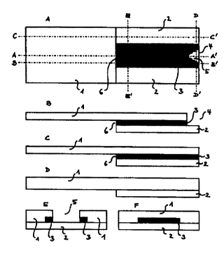
Various views (Figures lA to 1F) of a particularly
preferred embodiment of the test element according to
the invention are shown schematically in Figure 1. The
views shown are intended to give a three-dimensional
impression of the test element according to the
invention. The test element is composed of a carrier (1)
which is shaped such that the area which is covered by
the detection element (2) forms a capillary channel (3)
together with this detection element. For example a
depression can be stamped or milled into the carrier. In
the embodiment shown, a notch (5) is provided in the
carrier (1) on the sample application opening (4) of the
test element which enables the liquid drop to be
directly contacted with the capillary active zone (3)
when the sample is applied. A vent opening (6) is
located on the side of the capillary channel (3) that is
opposite to the sample application opening (4) which
allows air to escape when the capillary channel is
filled with sample liquid.
The capillary zone (3) extends from the sample
CA 02311496 2000-OS-19
- 20 -
application opening (4) to the opposite end of the
detection element (2) and thus ensures a homogeneous
sample distribution over the detection element (2). The
sample application opening (4) and vent opening (6)
limit the capillary active region (3) in the direction
of capillary transport.
When using the test element shown, the sample
application opening (4) of the test element is for
example contacted with a blood drop located on a
fingertip. In this process the blood drop comes into
contact with the exposed surface which is optionally
hydrophilized and simultaneously with the capillary
channel (3) through the notch (5) in the carrier (1).
The capillary channel fills itself with sample until it
is filled from the sample application opening (4) to the
vent opening (6). Afterwards the test carrier is removed
from the patient's finger which ensures that only the
sample that is present in the capillary channel (3) is
available for the detection element (2).
A further particularly preferred embodiment is shown in
Figure 2 as an alternative to the test element shown in
Figure 1. The partial views Figure 2A to 2F are intended
to also give a spatial impression of the test element
according to the invention. The test element shown
contains a channel (3) capable of capillary liquid
transport which is formed by an inert carrier (1), the
detection element (2) and a cover (7). The cover (7) and
the detection element (2) are mounted end to end in such
a way that the capillary channel (3) extends without
interruption from the sample application opening (4) to
the vent opening (6). The test element shown also
contains a notch (5) which facilitates penetration of
the sample liquid into the capillary channel.
CA 02311496 2000-OS-19
- 21 -
Figure 3 shows schematically on the basis of various
views (Figure 3A to 3F) how use of a gap cover foil (8)
can reliably prevent the capillary active zone (3) from
breaking down at the contact site between the detection
element (2) and cover (7). The gap cover foil (8) can
additionally be provided with a hydrophilic surface on
the side facing the capillary channel (3) which
facilitates the capillary transport of a liquid drop
from the sample application opening (4) to the vent
opening (6). Such a hydrophilization in the area of the
notch (5) in the carrier (1) is particularly
advantageous since it accelerates the penetration of the
sample material into the capillary channel.
In contrast to the particularly preferred embodiments of
the test carrier according to the invention shown in
Figures 1 to 3, the geometry of the capillary channel
(3) in the test element shown in Figure 4, which is also
a particularly preferred embodiment of the subject
matter of the invention, is not determined by the shape
of the carrier (1) but rather primarily by an
intermediate layer (9). Figures 4A to 4D are in turn
intended to give a three-dimensional impression of the
test carrier construction. The intermediate layer (9)
can be made of a double-sided adhesive tape which, apart
from determining the capillary channel geometry, also
serves to bond the other components that are involved in
forming the capillary active zone (3) i.e. the carrier
(1), cover (7) and detection element (2). The cover (7)
and the detection element (2) in the test element shown
are again mounted to closely end to end that the
capillary channel (3) extends without interruption from
the notch (5) at the sample application opening (4) to
the vent opening (6).
CA 02311496 2000-OS-19
- 22 -
The test element shown in various views in Figures 5A to
5F is a very specially preferred embodiment of the
subject matter of the invention. It combines all
components and thus other advantages of the test
elements which are shown in Figures 1 to 4.
An intermediate layer (9) is mounted on a carrier (1) in
the form of a double-sided adhesive tape. In the area of
the capillary channel (3) the intermediate layer (9) has
a recess which determines the length and width of the
channel (3). Its height is given by the thickness of the
intermediate layer (9). On the side of the capillary
channel (3) which is opposite to the carrier (1), a
cover (7) is located adjacent to the detection element
(3). A gap cover foil (8) is provided to ensure
capillary continuity. This can be hydrophilized to
enable a rapid transport of sample from the sample
application opening (4) to the vent opening (6) which
marks the opposite end of the capillary channel. An
additional advantage of the hydrophilization is that a
drop of sample liquid can be applied directly to a
hydrophilic surface in the area of the notch (5) which
is surrounded on several boundary sides by the capillary
active zone (3). This leads to a rapid penetration of
the liquid drop into the test element.
Figure 5G shows how the intermediate layer (9) can be
covered by a protective foil (10) in order to cover
exposed areas of the adhesive tape. However, in this
case the vent opening (6) must not be covered.
Finally a detail enlargement of a perspective view of
the sample application area of a particularly preferred
embodiment of the test element according to the
CA 02311496 2000-OS-19
- 23 -
invention is shown in Figure 6. The notch (5) in the
carrier (1) facilitates penetration of a sample liquid
from the sample application opening (4) into the
capillary active zone (3) which in the present case is
formed by the carrier (1), intermediate layer (9) and
cover (7). In addition to the shape shown the notch can
also have any other desired shape which serves the
purpose according to the invention.
Example 1
Manufacture of the analytical test element according to
the invention
A double-sided adhesive tape with a thickness of 100 ~cm
is glued onto a 350 ~,m thick foil of polyethylene
terephthalate (Melinex~, ICI, Frankfurt am Main,
Germany) coated with a 30 nm thick layer of aluminium
which was completely oxidized with water vapour. The
foil has a length of 25 mm and is 5 mm wide. A central
notch-shaped recess of 1 mm width and 2 mm length is
located on one of the short sides. The adhesive tape has
a punched hole of 2 mm width and more than 15 mm length
which defines the dimensions of the capillary channel.
The length of the punched hole is selected to be
slightly larger than the desired length of the
capillary-active channel which is determined by its
cover in order to ensure venting of the channel during
filling with sample liquid. A 3 mm long and 5 mm wide
detection film is glued onto the side of the adhesive
tape which provides the venting at a distance of 1 mm
from the end of the punched hole. A film is used as the
detection film as is known from the German Patent
Application No. P 196 29 656Ø The detection film is
specific for the detection of glucose. A 12 mm long and
5 mm wide cover layer is glued onto the region of the
CA 02311496 2000-OS-19
- 24 -
adhesive tape that is still open between the notch-
shaped recess and detection film so that the cover layer
and detection film abut one another. The cover layer is
composed of a 150 ~Cm thick polyethylene terephthalate
foil provided on one side with adhesive onto which a
6 ~cm thick polyethylene terephthalate foil (both:
Hostaphan~, Hoechst, Frankfurt am Main, Germany) coated
with a 30 nm thick oxidized aluminium layer on the side
facing the capillary channel is glued. In this case the
thinner foil extends ca. 500 ~m beyond the thicker foil
on the side facing the detection film. When the cover
layer is mounted on the adhesive tape care must be taken
that the protruding end of the thinner foil comes to lie
between the detection element and the thicker foil of
the cover layer. In order to cover areas of the adhesive
foil that are still exposed, these are covered with a
175 ~,m thick Melinex~ foil without, however, covering
functional areas.
The test element obtained in this manner has a capillary
channel of 15 mm length, 2 mm width and 0.1 mm height.
The channel can take up 3 ul sample liquid. An area of
3 mm x 2 mm of the detection film is wetted by the
sample.
Example 2
Measurement of the blood glucose concentration with the
aid of the test element from example 1
A drop of sample liquid is placed on the sample
application site of the test element from example 1. The
capillary of the test element automatically fills with
sample within 2 s. If glucose is present in the sample a
colour development is visible in the detection film
CA 02311496 2000-OS-19
- 25 -
after a few seconds. The end point of the reaction is
reached after ca. 30 to 35 s. The colour obtained can be
correlated with the glucose concentration of the sample
and either evaluated visually or by reflection
photometry.