Note: Descriptions are shown in the official language in which they were submitted.
CA 02311776 2000-05-26
Translation of PCTfEP98Z07619
Slag Crusher
Description
This invention relates to a slag crusher at the outlet of a
radiation cooler or gasification reactor with quenching sec-
tion, comprising a flooded pressure housing as well as a
shaft extending through the housing and comprising rotating
cutting knives, inlet baffle plates in a funnel-shaped
arrangement, and stationary cutting knives.
Slag crushers are used for crushing lumpy mineral slags and
unburnt residues, as they are produced in combustion proc-
esses or in the gasification of coal.
From DE 42 20 265 Cl there is known an apparatus for produc-
ing gas to be used in firing plants.
The apparatus comprises a reactor housing that is water-
cooled with respect to its wall portions. Inside the reactor
housing there is disposed a stepped reactor bottom carrying
the material to be gasified, which reactor bottom is divided
into several stationary portions and between the same into
incorporated movable portions. Supply lines for the gasifica-
CA 02311776 2000-05-26
_ 2 _
tion medium are associated to the movable portions. In direc-
tion of movement of the material to be gasified behind the
reactor bottom there is provided an ash discharge including a
discharge worm having crushing elements. Above the lower end
of the reactor bottom there is provided a water-cooled rotat-
ing slag crusher with water-cooled crushing teeth provided on
its periphery. Below the lower end of the reactor bottom
there is disposed an ash collecting chamber with a discharge
worm which likewise has crushing elements on its periphery.
In the case of a slag crusher developed by the applicants for
oil or coal gasification plants, which is disposed at the
outlet of a radiation cooler or a gasification reactor with
chilling or quenching section, the crushing operation takes
place in a w~ter bath under the process pressure. Correspond-
ing to the process conditions, the housing of the slag
crusher is pressure-proof. The passage of the drive shaft of
the cutting knives through the pressure housing has been ef-
fected by means of a pressure-tight stuffing box sealing sys-
tem with sealing water.
The actual crushing operation inside the pressure housing is
performed by rotating cutting knives. The stationary cutting
knives serve as shoulder or thrust bearing when crushing the
large slag lumps by means of the knives disposed on a rotat-
ing shaft.
A disadvantage of this slag crusher is the centric arrange-
ment of the shaft in the pressure housing with the rotating
knives between the radial and axial inlet baffle plates dis-
posed on both sides and the stationary knives disposed on one
side of the radial baffle plates.
The uncrushed and too large slag lumps pile up above the ro-
tating knives and are again and again pushed upwards through
the too small opening between the baffle plates provided on
CA 02311776 2007-04-18
3
both sides and are not supplied to the knives. There is a pile-up of material
above
the rotating shaft, which leads to an interruption of the flow of material and
impairs a
controlled crushing and removal of slag.
It is therefore the object unoerlying the invention to arrange the cutting
tools such
that both small and large slag pieces are seized completely and a controlled
crushing
and removal of the slag from the slag crusher is effected.
The solution of the object is effected in accordance with the main claim; the
sub-
claims represent advantageous aspects of the invention.
Due to the inventive arrangement and design of the rotating and stationary
knives a
controlled supply of material to the crushing points is ensured. By means of
the
arrangement and allocation of the cutting and stationary knives and their
distances
from each other a good crushing result and a high crushing efficiency are
achieved.
The stationary cutting knives have a long leg and a short leg. Into the
stationary
cutting knife a circular recess verging into a straight line has been made on
the side
of the long leg, and on the side of the short leg only an arcuate recess has
been
made, based on the vertical center line of the pressure vessel.
The stationary cutting knives are releasably mounted on brackets inside the
pressure
vessel; the dimensions of the long and short legs depend on the location of
the
stationary knife with respect to the outer wall of the pressure vessel, where
the length
of each stationary knife depends on the arrangement with respect to the center
line
and on the arrangement with respect to the round wall of the pressure vessel
in the
cutting position inside the pressure vessel.
CA 02311776 2007-04-18
4
Both the cutting and the stationary knives are exposed to an enormous wear in
the
cutting area. Therefore, these areas are provided with a wear protection. This
wear
protection can be achieved by means of a build-up weld or a mechanically
applied
wear protection. Of course, all knives can also be replaced as a complete
unit, when
a prolonged wearing operation has lead to a wear of the knife bodies.
The passages of the drive shaft through the pressure vessel are sealed by
means of
special stuffing boxes with a lubricating or rinsing system. The support and
the drive
of the drive shaft are disposed outside the pressure vessel. The shaft
extending
through the pressure vessel is disposed at a distance "a" from the vertical or
horizontal center line.
The invention wili now be explained in detail with reference to an embodiment,
wherein:
Fig. I 5 ~ov~s a ve~iicai section through a siag crusher in the sectional
plane of
the drive shaft,
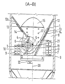
Fig. 2 shows a section A - B through the slag crusher,
Fig. 3 shows a horizontal section C - D through the slag crusher in the
sectional plane of the drive shaft,
Fig. 4 shows a side view of a stationary cutting knife,
Fig. 5 shows a view E of a stationary cutting knife.
As is represented in Fig. 1 the slag crusher consists of the pressure vessel
1, the
drive shaft 2, stuffing boxes 3 provided on both sides, the rotating knives 4
mounted
on the shaft 2 as well as the stationary knives 7 disposed below the inlet
baffle plate
12 and between the baffle plates 15 of the feeding hopper. This material to be
CA 02311776 2007-04-18
crushed is supplied to the crushing area via the baffle plates 12, 15 of the
feeding
hopper. The rotating knives 4 are connected to the shaft 2 by the fixture 5.
The
stationary knives 7 are connected to the mounting brackets 8. The inlet baffie
plate
12 is connected to the mounting bracket 13 and the inlet baffle plate 15 is
connected
to the mounting bracket 16. The crushed material after crushing falfs in the
cone 18
and leaves the slag crusher through the slag crusher outlet 19. In the middle
of the
substantially cylindrical pressure housing 1 the vertical center line 20 is
drawn.
In accordance with Fig. 2, the drive shaft 2 is disposed eccentrically or off-
center at a
distance "a" from the vertical center line 20 of the slag crusher, so that the
crushing
area is concentrated in the middle of the slag crusher. In this way, a uniform
load of.
the fixture 5 of the rotating knives 4 is achieved as well as a central
discharge of the
crushed material.
On the drive shaft 2 the rotating cutting knives 4 are disposed. As a halved
version,
the rotating cutting knives 4 are fixedly connected with the drive shaft 2
through the
fixture 5 by means of fastening screws and a feather key 6. When crushing the
material to be crushed, the crushing shoulders of the rotating cutting knives
4 form
the stationary cutting knives 7 protruding through the inlet baffle plate 12,
which
stationary cutting knives 7 are provided with a wear-resistant build-up weld
11. They
are each mounted individually on mounting brackets 8, 10 by means of fastening
screws 9. The slotted inlet baffle plate 12a and the inlet baffle plate 12 are
connected to mounting brackets 13 by means of fastening screws 14, and the
inlet
baffle plate 15 is fixed by means of fastening screws 17. Also drawn in Fig. 2
are a
horizontal center line 21 of the pressure housing 1 and the vertical center
line 22 of
the shaft 2.
The rntatinn riittinr. I-;;iv S 4 are an uiari-~ o~iset in a known manner on
the eriPhe
~.,....,.yg Y P rY
of the shaft 2, so that it is achieved that during the crushing operation only
one
rotating knife 4 and two stationary knives 7 are each in engagement with each
other
as crushing shoulder or pairs of knives 7, and the further knives 4 are used
only
subsequently. When designing the motor, the crushing force of only one
rotating
cutting knife 4 should therefore be considered.
An essential feature of the inventive apparatus consists in that all interior
cutting
members 4, 7, which are exposed to wear, can quickly be replaced if necessary.
CA 02311776 2007-04-18
6
The crushed material is discharged from the slag crusher via the cone 18 and
the
outlet port 19 and supplied to a disposal site.
Fig. 3 shows a horizontal section C - D through the slag crusher in the
sectional
plane of the drive shaft 2. The drive shaft 2 is supported in two lateral
ports 1a in
roller bearings 3a and secured against escaping pressurized water by means of
sealing elements of the stuffing boxes 3.
The shaft 2 with the rotating cutting knives 4 is disposed inside the pressure
housing 1 off-center or eccentrically at a distance "a" from the horizontal
center line
21 of the pressure vessel 1.
The stationary cutting knives 7 are provided in slots of the inlet baffle
plates 12,
which in turn are mounted at brackets 8 and 13. In the vicinity of the sealing
near the
wall of the housing 1 there are provided inlet baffle plates 15 off-set by 90
. The inlet
baffle plates 12, 12a and 15 form the so-called feeding or material hopper for
the
cutting knives 4, 7. The slag crusher outlet 19 is shown in the middle of the
pressure
housing 1 by broken lines.
Fig. 4 shows a side view of a stationary cutting knife 7 with a long leg 7a
and a short
leg 7b, which on the first-mentioned side 7a has an arcuate recess 7d verging
into a
straight line 7c, and on the last-mentioned side 7b only has a circular recess
7d,
based on the vertical center line 22 of the shaft 2.
On both legs 7a, 7b guiding strips 23, 24 are provided. The straight portion
7c of the
stationary cutting knife 7 is provided on its reverse side with a build-up
weld or wear-
resistant coating 11.
CA 02311776 2007-04-18
7
Fig. 5 shows a view E of the stationary cutting knife 7 with a long leg 7a and
a short
leg 7b, based on the horizontai center line 21 of the shaft. On both sides of
the
stationary cutting knives 7 guiding strips 23, 24 are provided.
CA 02311776 2007-04-18
8
List of Reference Numerals:
1 pressure housing
1a port
2 shaft
3 stuffing box
3a roller bearing
4 rotating cutting knife
fixture of the rotating cutting knife
6 feather key
7 stationary cutting knife
7a long leg
7b short leg
7c straight portion
7d circular recess
8 mounting bracket for stationary cutting knives
9 fastening means
mounting bracket for stationary cutting knives
11 build-up weld/wear-resistant coatings
12 inlet baffle plate
12a slotted inlet baffle plate
13 mounting bracket for inlet baffle plate
14 fastening screws
inlet baffle piate
16 mounting bracket for inlet baffle plate
17 fastening screws
18 cone
19 slag crusher outlet
vertical center line of 1
21 horizontal center line of 1
22 vertical center line of 2
23 guiding strips
24 guiding strips
"a" distance between 20 and 22