Note: Descriptions are shown in the official language in which they were submitted.
CA 02311916 2000-06-19
TITLE OF THE INVENTION
IMPROVED WIRE MESH AND LATH
FIELD OF THE INVENTION
This invention relates to metal wire mesh. In particular, this invention
relates to an
improved structure for metal wire mesh to avoid the problem of curvature set
when wire
mesh is bent or wound in rolls.
BACKGROUND OF INVENTION
Many metal wire mesh products comprise a plurality of round longitudinal wires
and a
plurality of round transverse wires forming a plurality of rectangles. These
products
include welded wire meshes or wire laths, or other meshes that are twisted or
fastened
together in some manner at the intersections of the longitudinal and
transverse wires.
Examples of the first type are welded concrete reinforcing mesh, welded
utility mesh, or
welded stucco reinforcing lath. An example of the latter type is wire fencing.
For wire meshes of lighter wire sizes, it is common to wind these products
into rolls.
Rolls provide the advantage of a convenient package containing a considerable
length of
continuous material. Rolls can provide a compact and dense package, which is
important
for warehousing and shipping considerations. Further, wire mesh products
formed into
rolls can easily be placed on pallets for handling.
However, one of the drawbacks of rolling metal wire mesh products into rolls
is that the
longitudinal wires can take on a curvature set. For the user, such curvature
set often
presents a problem. When unrolling the product, the longitudinal wires retain
a memory
and a tendency to spring back to the rolled position. As most products are
intended to
lay or run flat, or in a straight line, the user must work against the
tendency of the mesh
to spring back to its rolled condition. This can be dangerous for the user,
and makes it
1
CA 02311916 2000-06-19
difficult to flatten the product as it is being applied or while the wire mesh
is being
further processed.
The curvature set is caused when the longitudinal wires are bent into the roll
shape. The
S resulting curvature stretches the outside fibres of the metal wires beyond
their elastic
limit. The metal at the outer side of each wire becomes plastically deformed
and retains
the memory of this deformation. The curvature set is primarily a function of
the wire
size, the ductility of the metal and the radius of the roll.
To partially counter the problem of curvature set, some manufacturers have
produced
rolls having larger core diameters. This approach can reduce the problem to
some extent
but will not eliminate it entirely, unless inordinately large roll core
diameters are used.
This approach also results in larger outer roll diameters for the same length
of product
and therefore, the advantages of a dense package are not fully achieved.
Producing and packaging metal wire mesh in sheets avoids the curvature set
that is
created in the roll formation process but this approach loses some of the
benefits which
rolls provide. Wire mesh products in sheet form require additional packaging
to protect
the product and to create a package that can be handled by a forklift. Another
disadvantage of sheets is that they can be more difficult for the user to
handle in the field.
A further disadvantage for certain applications such as wire stucco
reinforcement is that
sheets require additional end overlaps in the construction of a wall. This
reduces both the
efficiency of application and the quality of installation in comparison to
rolls which
contain longer continuous lengths.
U.S. Patent Nos. 3632054, 3688810, 3814144, 4077731, 4557633, and 5009545 all
acknowledge the problems associated with wire meshes in rolls and disclose
various
apparatus and methods for straightening, backbending, decontouring the web and
flattening the roll, so that when it is unrolled the tendency of the wire mesh
to reassume a
rolled position is substantially eliminated. These approaches compensate for
the problem
of curvature set but they do not avoid the introduction of curvature set in
the first place.
2
CA 02311916 2000-06-19
The object of the present invention is to reduce the curvature set of
longitudinal wires in
metallic wire meshes that are wound into rolls for packaging or transport and
are intended
to be unrolled prior to use.
The present invention has application to wire mesh comprising a plurality of
longitudinal
strands and a plurality of transverse strands forming a plurality of
rectangles, where the
longitudinal strands are continuous and the transverse strands are either
continuous or
segmented, and the mesh or fencing is held together by welding or mechanical
fastening
at each intersection.
SUMMARY OF THE INVENTION
According to the invention, the longitudinal wires of a metal wire mesh are
shaped so that
1 S instead of their cross section being round, the cross section is
relatively shorter in one
direction than in the other. For a round shape, the moment of inertia is the
same around
the horizontal and vertical neutral axes. The objective of the invention is to
change the
profile of the longitudinal wires so that the moment of inertia around the
horizontal axis
is less than the moment of inertia around the vertical axes (for the purpose
of defining
horizontal and vertical, the above description is based on the mesh laying in
a horizontal
plane.). This includes a flattened profile, an oval profile, a convex profile,
or any other
profile that generally reshapes the round wire to a degree sufficient to meet
the desired
obj ective.
This shaping of the wire from drawn round wire, either coated or uncoated, or
from a hot
rolled wire rod can occur either before, during or after manufacturing of the
wire mesh.
The shaping of the wires can also be continuous or intermittent along the
length of each
longitudinal wire or in relation to adj acent longitudinal wires.
By reducing the moment of inertia of the longitudinal wires in the direction
as described,
the wire mesh can be rolled into a roll and some, or all, of the product in
the roll can be
3
CA 02311916 2000-06-19
wound up without acquiring curvature set. Thus, when the product is unrolled
the wire
mesh can easily be returned either to the flat state or have a desired amount
of curvature.
It is a further object of the present invention to provide metal wire mesh
that can be
packaged in rolls and then subsequently unwound and that will then
substantially flatten
itself without the need for separate apparatus.
The factors that determine whether the longitudinal wires of a metal wire mesh
take on
any circular memory is the roll diameter and horizontal moment of inertia of
the
longitudinal wires. The manufacturer has the option of changing these
attributes to either
totally eliminate circular memory, or use some other combinations to both
reduce circular
memory and obtain other packaging benefits.
With minimal curvature set, greater density of rolled product can be achieved
for
warehousing and shipping.
The invention also provides an advantage in certain applications of providing
a product
that is more supple, such being an important feature for products such as
stucco wire
reinforcement lath or concrete reinforcing mesh in sheet form that need to be
temporarily
bent to get around corners. It will therefore be appreciated that the wire
mesh structure of
the invention will have application not only to metal wire mesh product which
is intended
to be packaged in rolls, but also to product in sheet form that is likely to
be subject to
temporary bending.
This invention can be applied to wire meshes made of any metallic material
including
bright, galvanized, plated or coated iron, carbon or alloyed steel; or from
aluminum,
stainless steel, brass, or other non-ferrous metals.
In one aspect, the invention is a metal wire mesh consisting of a plurality of
longitudinal
wires and a plurality of transverse wires, said wire mesh being wound into
rolls along the
length of said longitudinal wires and intended to be unrolled prior to use.
The
4
CA 02311916 2000-06-19
longitudinal wires have shaped areas wherein the moment of inertia of said
shaped areas
about the neutral axis parallel to the plane of the mesh is 90 percent or less
of the moment
of inertia of the shaped areas about the neutral axis vertical to the plane of
the mesh. In
another aspect, the invention is such wire mesh in sheet form.
According to the invention, a significant proportion of the longitudinal wires
are shaped,
namely at least 10%.
The advantages of the invention may be achieved when a significant proportion
of the
length of each shaped longitudinal wire is shaped, preferably at least 15%.
In another aspect of the invention, the areas at the intersections of the
longitudinal and
transverse wires are not shaped but the areas between the intersections are
shaped.
Other aspects of the invention will be appreciated by reference to the
detailed description
which follows as well as to the claims.
BRIEF DESCRIPTION OF THE DRAWINGS
Fig. 1 is a side sectional view of a welded wire mesh with flattened
longitudinal strands
in accordance with the present invention;
Fig. 2 is a side sectional view of a welded wire mesh with longitudinal
strands that are
flattened on one side and rounded on the opposite side in accordance with the
present
invention;
Fig. 3 is a side sectional view of a welded wire mesh with oval longitudinal
strands in
accordance with the present invention;
Fig. 4 is a side sectional view of a welded wire mesh with convex shaped
longitudinal
strands in accordance with the present invention;
5
CA 02311916 2000-06-19
Fig. 5 is a side sectional view of a welded wire mesh with concave shaped
longitudinal
strands in accordance with the present invention;
Fig. 6A is a side sectional view of a hinge joint metal wire fence with
flattened
longitudinal strands in accordance with the present invention;
Fig 6B is a front view of the hinge joint fence as shown in Fig. 6A;
Fig. 7A is a side sectional view of a metal wire fence utilizing locking wires
and with
flattened longitudinal strands in accordance with the present invention;
Fig. 7B is a front view of the wire fence as shown in Fig. 7A;
1 S Fig. 8 is a front view of a metal wire mesh that shows intermittent
flattening of the
longitudinal strands in accordance with the present invention;
Fig. 9 is a side sectional view of a wire intersection showing the
relationship of the axis
of the shaped longitudinal strands in relation to the plane of the mesh in
accordance with
the present invention;
DETAILED DESCRIPTION OF THE PREFERRED AND ALTERNATIVE
EMBODIMENTS OF THE INVENTION
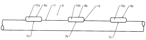
Fig. 1 shows a metal wire mesh 9 in a preferred form of the present invention.
The mesh
9 includes a series of transverse strands 11 and a series of longitudinal
strands 10a, lOb,
lOc arranged in a generally planar configuration and extending laterally and
generally
parallel to one another. Typically the mesh would be produced in lengths and
the number
of longitudinal strands would be a function of the spacing of the strands and
the overall
width of the product. In the case of welded stucco reinforcement lath, the
width ranges
from 36 inches to 54 inches, although the invention is of course not limited
to these
6
CA 02311916 2000-06-19
widths. The number of transverse strands is determined by the spacing of the
transverse
strands and the length of the package. Typically, the length of product is 4
feet to 20 feet
for sheet products, and 100 feet to 150 feet for rolled products, although
again the
invention is not limited to these lengths.
As shown in Fig. 1, each of the longitudinal strands 10a, lOb, lOc has a
flattened profile
and includes a flat portion 8a, 8b, 8c on the outward face and a flat portion
7a, 7b, 7c on
the inward face. These flat portions lie generally in the plane of the mesh or
lath.
At the intersection of the transverse strands 11 and the longitudinal strands
10a, l Ob, l Oc,
the strands are joined together by resistance welding. Resistance welding
techniques are
well known and are utilized in many wire fabricating applications. During the
welding
process, there is a setting down of the intersecting strands into each other
as shown at
point 12.
Fig 2 show an alternate form of the present invention in which a wire mesh is
constructed
in much the same manner as that of Fig 1, except that the longitudinal strands
13 have
one side flat 13a and one rounded side 13b. In Fig 2, the flat side 13a is
placed inward
against the transverse wire 11 and the rounded side is facing outward from the
plane of
the mesh. Although not shown in a figure, the opposite combination of placing
the
rounded side 13b against the transverse wire 11 and having the flat side 13a
facing
outward from the plane of the mesh is another alternative embodiment.
Fig. 3 shows another alternate form of the present invention in which a wire
mesh is
constructed in much the same manner as that of Fig 1, except that the
longitudinal strands
14 have an oval shape.
Fig. 4 shows another alternate form of the present invention in which a wire
mesh is
constructed in much the same manner as that of Fig 1, except that the
longitudinal strands
15 have a convex shape.
7
CA 02311916 2000-06-19
Fig. S shows another alternate form of the present invention in which a wire
mesh is
constructed in much the same manner as that of Fig 1, except that the
longitudinal strands
16 have a concave shape.
Fig 6A shows a further embodiment, in which wire fencing, referred to as a
hinge joint
style of fencing, is made of a series of longitudinal strands 17 and a series
of transverse
strands 18, 19. The transverse strands 18, 19 are called stay wires and are
made of
individual wire segments 18, 19 between each longitudinal strand 17. At each
intersection, the stay wires 18, 19 are twisted around the longitudinal strand
17 to form a
tight twist to hold the fence together. In this embodiment of the present
invention, Fig 6A
shows that the fence is constructed with longitudinal strands 17 which are
flattened. The
two flat surfaces are oriented so that the flat surfaces lie generally in the
same plane as
the fence plane. Fig 6B shows a front view of the hinge joint fence
intersection shown in
Fig 6A.
Fig 7A shows another embodiment in which wire fencing, referred to as a 'stiff
stay'
style of fence which is made up of a series of longitudinal strands 20, a
series of
transverse strands 21, and a locking wire segment or ring 22 at each
intersection. In
contrast to the fencing in Fig 6, the transverse strands 21, called stay
wires, are
continuous across the width of the fence. At each intersection, the locking
wire segment
or ring 22 locks the longitudinal strands 20 and stay wires 21 together. In
this
embodiment of the present invention, the fence is constructed of longitudinal
strands 20
which are flattened. The two flat surfaces are oriented so that the flat
surfaces lie
generally in the same plane as the fence plane. Fig 7B shows a front view of
the fence
intersection shown in Fig 7A. As further shown in Fig 7A, the stay wire 21 may
be
crimped at each intersection to create an offset to prevent the longitudinal
strands from
slipping vertically.
With each of the embodiments shown of the present invention up this point, the
shaping
of the longitudinal strands has been continuous along the length of the
longitudinal
strand. However, it is not necessary to shape the longitudinal strands in
uninterrupted
8
CA 02311916 2000-06-19
fashion along their entire length to achieve some or all of the desired
benefits.
Accordingly, as shown in Fig. 8, Fig the shaping, in this case flattening, of
the
longitudinal strands 24a, 24b, 24c is not continuous but is intermittent. The
longitudinal
strands 24a, 24b, 24c are shaped as at 25a, 25b, 25c, 25d, 25e between the
transverse
strands 23a, 23b, 23c, 23d. The sections 26a, 26b, 25c, 25d between the
flattened sections
25a, 25b, 25c, 25d, 25e can be round or any other shape. The possible
combinations of
patterns and spacing for shaped and unshaped profiles along the length of the
longitudinal
strands is infinite. For any ratio whereby more than 15 % of the length of the
longitudinal strands are shaped, the desired benefits of the present invention
would be
achieved and are considered to be within the scope of the invention.
Similarly, it is not necessary to shape all the longitudinal strands to
achieve the benefits
of the present invention. For any ratio whereby more than 10 % of the
longitudinal
strands are shaped more than 15% of their length, the desired benefits of the
present
invention would be achieved and is considered to be within the scope of the
invention.
The preferred embodiments that have been used as examples have utilized
preferred
shapes of the longitudinal strands. Since variations in these shapes may also
obtain the
desired benefits of the present invention, it is useful to identify the
characterizing
parameters of the present invention.
The moment of inertia (I) of a cross sectional area is a well known concept in
engineering
and is used in beam calculations. Every cross section has two principal axes
passing
through the center of gravity, and these two axes are at right angles to each
other. A
moment of inertia may be calculated in relation to any given axis. Fig. 9
shows a cross
sectional view of a longitudinal strand 27 and a transverse strand 28. The two
principal
axes of the longitudinal strand 27 are shown as AA and BB. Axis AA is parallel
to the
plane of the wire mesh, lath, fence, or screen and axis BB is perpendicular to
the plane of
the wire mesh, lath, fence or screen. For a round shape, the moment of inertia
is the same
about each axis and is determined by the formula I= ~ d4/64. For other common
shapes,
9
CA 02311916 2000-06-19
there are specific formulas that have been developed to calculate I, and there
are accepted
methods to calculate I for unusual shapes.
Any shape of the longitudinal strands having a moment of inertia of the cross
section
about the neutral parallel to the plane of the mesh (AA) which is 90% or less
than the
moment of inertia about the neutral axis normal to the plane of the mesh (BB)
is within
the scope of the present invention.
Finally, while the embodiments shown and described herein disclose specific
preferred
shapes, it will be appreciated that any shape of the longitudinal strands in
each
embodiment would be subject to the present invention if the shaping falls
within the
limits as stated and ratios of the moments of inertia as stated.
While the invention has been described in preferred forms only, it will be
obvious to
those skilled in the art that modifications may be made thereto without
departing from the
spirit and scope of the invention as set forth in the following claims.