Note: Descriptions are shown in the official language in which they were submitted.
CA 02312294 2000-06-20
-2-
FIELD OF THE INVENTION
The present invention relates to improvements in warehouse product storage
systems
having a number of carts movably supported on a rail assembly. The rail
assembly has
linear rails providing tracks for wheels supporting the carts on the rails.
The carts carry
pallet loaded with containers, cartons, or products.
BACKGROUND OF THE INVENTION
Product inventories are warehoused where they can be quickly and efficiently
stored and retrieved to accommodate marketing and consumer demands. Warehouse
storage rack structures having a plurality of rows of vertically stacked bays
are used to
store pallets supporting containers, cartons, or products. Each bay has rail
assemblies
providing parallel tracks for the wheels of carts carrying the pallets.
Examples of
warehouse storage rack structures having movable carts for carrying pallets
are described
in the following U.S. Patents.
E. Doring in U.S. Patent 4,341,313 discloses a pallet shelving structure
having
inclined rails accommodating carriages for supporting pallets. The pallets are
loaded and
unloaded from the carriages at one end of the rails to reduce the passageway
area required
for using the shelving structure.
T. Scott et al in U.S. Patent 5,393,188 discloses a pallet storage system
having
rectangular rails and U-shaped carts. The rails have top surfaces for cart
wheels which ride
on inner and outer top edges of the rails. The carts are sized so that carts
overlap each
other when located in the loading positions of the carts.
SUMMARY OF THE INVENTION
The invention is a pushback cart storage apparatus for pallets used to carry
loads,
CA 02312294 2000-06-20
-3-
such as cartons, containers, and products. The apparatus has a track assembly
and carts
movably associated with the track assembly that can be installed on and is
compatible with
conventional racks used in warehouses for storing pallets carrying loads. The
carts have
relatively low profiles which increase vertical pallet space and provide extra
lift clearance
during loading and unloading of pallets from the carts. The increased vertical
pallet space
increases warehouse product storage capacity. The carts have longitudinal side
members
secured to a horizontal deck which can accommodate a variety of pallet weights
and sizes
including pallets carrying heavy loads. The decks and side members of the
carts have
stability due to vertical, horizontal and torsional strength of these combined
structures.
The carts have wheels that ride on upper and lower tracks of the rails of the
track assembly
to allow the carts to be located in generally vertical stacked locations and
movable to
generally end-to-end positions when loaded with pallets. The rails comprise
step box
beams that have parallel upper and lower top tracks. One or more carts movably
supported
on the lower tracks interengage one or more carts that ride on the upper
tracks to permit
vertical stacking of the carts and control relative movement of the carts
along the tracks.
The preferred embodiment of the apparatus for storing pallets used to carry
loads
has a track assembly mounted on a rack structure used in a warehouse to store
products.
The track assembly has a pair of parallel linear rails. Each rail is a step
box beam having
upper and lower tracks providing continuous longitudinal surfaces for the
wheels of carts
for supporting pallets canying loads. Each rail has first and second side
walls joined to a
bottom wall, an upright middle wall located between the upright side walls,
and upper and
lower top walls having the upper and lower tracks. The upper top wall is
joined to the first
side wall and the top of the middle wall. The lower top wall is joined to the
second side
wall and the bottom of the middle wall to locate the lower track below the
horizontal plane
CA 02312294 2000-06-20
-4-
of the upper top wall. The lower top wall slopes or inclines downwardly and
inwardly
from the second side wall to the middle wall to enhance the linear tracking of
the wheels
riding on the lower tracks of the rails. Each of the carts have a pair of
parallel and laterally
spaced side members and a deck extended between and secured to the side
members. The
deck covers substantially the entire area between the side members. The deck
has a
plurality of side-by-side transverse panels having transverse side flanges and
downwardly
extended transverse ribs. Opposite ends of the panels are secured with welds
to the side
members. An alternative deck can be a sheet metal panel having transverse
reinforcing
ribs or corrugations. The cart side members are channel members having upper
flanges
and lower upwardly directed flanges that contact and are secured to side
portions of the
deck. The side portions of the deck are located between the upper and lower
flanges of the
side members to firmly secure the deck to the side members. The lower flange
also
provides support for the deck.
Wheels rotatably mounted on axles connected to opposite ends of the side
members
position the carts on the rails. Brackets secured to the second and subsequent
carts
accommodate the axles. The vertical lengths of the brackets vary to allow the
carts to be
located in a vertical stacked location at the loading and unloading end of the
track
assembly.
The advantages and objects of the pushback cart storage apparatus of the
invention
are embodied in the following detailed description taken in connection with
the drawing
DESCRIPTION OF THE DRAWINGS
Figure 1 is a top plan view of a pushback storage system having the multiple
cart
and track assembly of the invention;
Figure 2 is a side elevational view of Figure 1;
CA 02312294 2000-06-20
-5-
Figure 3 is an enlarged sectional view taken along line 3-3 of Figure 1;
Figure 4 is a foreshortened enlarged sectional view, taken along line 4-4 of
Figure
1;
Figure 5 is a top plan view of the track assembly of Figure 1;
Figure 6 is a side elevational view of the track assembly of Figure 4;
Figure 7 is an enlarged end elevational view of the loading end of the track
assembly of Figure 5;
Figure 8 is an enlarged sectional view taken along line 8-8 of Figure 5;
Figure 9 is an enlarged end elevational view of the distal or rear end of the
track
assembly of Figure 5 viewing along the line 9-9 of Figure 5;
Figure 10 is an enlarged side elevational view of the distal end of the track
assembly of Figure 5 viewing along the line 10-10 of Figure 5;
Figure 11 is an enlarged sectional view taken along line 11-11 of Figure 5;
Figure 12 is a top plan view of the first cart of the pushback storage
apparatus;
Figure 13 is a sectional view taken along line 13-13 of Figure 12;
Figure 14 is an enlarged sectional view taken along the line 14-14 of Figure
12;
Figure 15 is an enlarged sectional view taken along the line 15-15 of Figure
12;
Figure 16 is an enlarged sectional view taken along the line 16-16 of Figure
12;
Figure 17 is a top plan view of the second cart of the pushback storage
apparatus;
Figure 18 is a side elevational view of Figure 17;
Figure 19 is an end elevational view of the right end of Figure 17, viewing
along
the line 19-19 of Figure 17;
Figure 20 is an enlarged foreshortened sectional view taken along line 20-20
of
Figure 17;
CA 02312294 2000-06-20
-6-
Figure 21 is an enlarged sectional view taken along line 21-21 of Figure 17;
Figure 22 is a top plan view of the third cart of the pushback storage
apparatus;
Figure 23 is a side elevational view of Figure 22;
Figure 24 is an end elevational view of the left end of Figure 22 viewing
along line
24-24 of Figure 22;
Figure 25 is an enlarged foreshortened sectional view taken along line 25-25
of
Figure 22;
Figure 26 is an enlarged sectional view taken along line 26-26 of Figure 22;
Figure 27 is a top plan view of the fourth cart of the pushback storage
apparatus;
Figure 28 is a side elevational view of Figure 27;
Figure 29 is an end elevational view of the right end of Figure 27 viewing
along
line 29-29 of Figure 27;
Figure 30 is an enlarged foreshortened sectional view taken along line 30-30
of
Figure 27;
Figure 31 is an enlarged sectional view taken along the line 31-31 of Figure
27;
Figure 32 is a side elevational view of the loading and unloading end of the
pushback storage system showing the stacked positions of the carts;
Figure 33 is a sectional view taken along line 33-33 of Figure 32;
Figure 34 is an enlarged sectional view taken along line 34-34 of Figure 33;
and
Figure 35 is an enlarged sectional view taken along line 35-35 of Figure 33
DESCRIPTION OF THE INVENTION
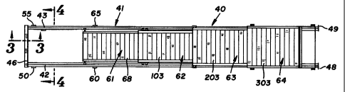
Referring to Figures 1 and 2, a pushback storage apparatus 40 has a plurality
of
carts 61, 62, 63 and 64 movably supported on an elongated track assembly 41.
Pushback
storage apparatus 40 is used in warehouse storage rack structures having
vertically stacked
CA 02312294 2000-06-20
-7-
bays for accommodating pallets, containers and cartons supporting products,
herein defined
as loads. Each bay has a number of vertical arranged pushback storage
apparatus 40. Each
pushback storage apparatus 40 accommodates up to five pallets. The pushback
apparatus
can accommodate two, three, four or five pallets. A warehouse storage rack
structure
having pushback carts movably supported on rails is shown in U.S. Patent No.
5,393,188.
As shown in Figures 5 and 6, track assembly 41 has a pair of laterally spaced
elongated
step box rails 42 and 43 secured to transverse supports 44 of the rack
structure. Track
assembly 41 slopes or inclines downwardly toward the loading and unloading end
of
apparatus 40. A transverse inverted channel member 46, shown in Figures 3, 4,
7 and 8, is
secured to the front or proximal ends of rails 42 and 43. The top back portion
47 of
member 46 is a transverse shoulder that extends above the top surfaces of
rails 42 and 43 to
provide a transverse stop for retaining a pallet on rails 42 and 43 adjacent
portion 47 of
member 46. Member 46 maintains the lateral spacing between rails 42 and 43 and
reduces
damage of the front portions of rails 42 and 43 by the pallet loading and
unloading
equipment, such as a fork lift, and the pallets. The distal or rear ends of
rails 42 and 43 are
secured to ears 48 and 49 which function as stops for cart 64. Ears 48 and 49
are flat plates
that project outwardly from the outsides of rails 42 and 43.
As shown in Figure 11, rail 43 is a tubular member having a cross section step
box
configuration comprising upright side walls 51 and 52 joined to a flat bottom
wall 53, an
upper top wall 54 and a lower top wall 56. Walls 54 and 56 have linear
surfaces providing
lower and upper tracks. An upright middle wall 57 is joined to walls 54 and
56. A
rounded corner 58 joins wall 56 to the lower part of wall 57. The angle 59
between walls
56 and 57 is less than 90 degrees. Wall 56 slopes downwardly in a transverse
direction
into rail 43. The slope of wall 56 is about 5 degrees relative to the
horizontal plane of
CA 02312294 2000-06-20
-8-
bottom wall 53. The slope or transverse incline of lower wall 56 can vary.
Upper top wall
54 and lower top wall 56 provide elongated linear upper and lower tracks for
the wheels of
carts 61-64. Two pairs of ears 50, 55 and 60, 65 are secured to the outsides
of rails 42 and
43. The ears 50, 55, 60 and 65 cooperate with brackets 311, 312, 313 and 314
of cart 64
when cart 64 is in the stacked position to prevent lifting and separation of
cart 64 from
track assembly 41. The fork lift used to unload a pallet from cart 64 may
inadvertently
engage cart 64 and attempt to lift cart 64 off of track assembly 41. Ears 50,
55, 60, and 65
retain cart 64 on track assembly 41 as the lower ends of brackets 311-314 hook
under ears
50, 55, 60, and 65 when cart 64 is lifted.
The first cart 61, shown in Figures 12 to 16, has a pair of elongated side
channel
members for beams 66 and 67 secured to opposite side edges of a deck 68. Deck
68 is a
continuous platform that can extend the full length of members 66 and 67 and
covers the
space between members 66 and 67 so as to provide cart 61 with a low profile.
Deck 68
does not extend above or below side members 66 and 67. Deck 68 comprises a
plurality of
side-by-side panels 69 having ends secured with welds to channel members 66
and 67.
The deck can be a sheet metal panel having transverse ribs, corrugations, or
other
reinforcing structures. As shown in Figure 15, each panel 69 has downwardly
directed
right angle side flanges 71 and 72 and can have transverse U-shaped ribs 73
and 74. Ribs
73 and 74 project downward providing the top of panel 69 with a pair of
transverse grooves
76 and 77. The flanges 71 and 72 and ribs 73 and 74 reinforce the panel and
provide deck
68 with a strong low profile. An alternative deck can be a plurality of side-
by-side sheet
metal panels having flat top walls and side flanges 71 and 72.
Cart 61 is movably supported on lower top walls 56 of rails 42 and 43 with
wheels
78, 79, 81 and 82. As shown in Figure 16, wheel 78 is mounted on a bolt or
axle 83
CA 02312294 2000-06-20
-9-
connected to channel member 66. Bolt 83 extends through a block or spacer 84
to locate
whee178 laterally away from channel member 66. A bearing 86 mounted on bolt 83
accommodates wheel 78. Bearing 86 located in a cavity 80 in whee178 is spaced
from
block 84 with a first sleeve 87. The sleeve 87 spaces rim 88 of whee178 from
block 84. A
nut 89 threaded on the inner end of bolt 88 retains bolt 83, block 84 and
whee178 in
assembled relation on channel member 66. Second sleeve 90 spaces the head of
bolt 83
from bearing 86. A second sleeve 90 spaces the head of bolt 83 from bearing
86. Bolt 83
clamps bearing 86 between sleeves 87 and 90.
Wheels 79, 81 and 82 are connected to ends of members 66 and 67 with bolt,
block,
and bearing structures that are the same as shown in Figure 16. Blocks 91, 92,
and 93
space wheels 79, 81 and 82 from adjacent channel members.
The second cart 62, shown in Figures 17-2 1, has a pair of elongated side
members
or beams 101 and 102 secured to opposite sides of deck 103. Deck 103 comprises
a
plurality of side-by-side transverse panels which could cover substantially
all the space
between members 101 and 102. The width of cart 62 is greater than the width of
cart 61 to
allow cart 62 to be located over cart 61 when the carts are in stacked or
nested
relationship, as shown in Figures 32 and 33. Each panel of deck 103 has the
same structure
as pane169 shown in Figure 15.
As shown in Figures 20 and 21, rail 101 has a generally horizontal top flange
105
and an upwardly and inwardly directed bottom flange 104. Deck 103 has a side
edge
located between flanges 104 and 105. The top of deck 103 is secured with welds
to flange
105. The ribs, corrugations or reinforcing structures of deck 103 are secured
to flange 104
with welds. The opposite side edge of deck 103 is secured to the flanges of
side member
102. The bottom flanges 104 of members 101 and 102 support loads carried by
deck 103.
CA 02312294 2000-06-20
-10-
Cart 62 is movably supported on lower top walls 56 of rails 42 and 43 with
wheels
107, 108, 109 and 110. Wheels 107 and 110 are operatively mounted on brackets
or plates
111 and 119 secured to opposite ends of side member 101. Plates 117 and 118 on
opposite
ends of side member 102 support wheels 108 and 109. As shown in Figure 21,
wheel 107
is rotatably mounted on a bolt 112 with a bearing 113. Bolt 112 extends
through a hole in
plate 111 and into a cavity 120 in wheel 107. A first sleeve 114 spaces the
inside flange
116 from plate 111. A second sleeve 115 spaces the head of bolt 112 from
bearing 113.
Bolt 112 clamps bearing 113 between sleeves 114 and 115 and fixes the lateral
position of
wheel 107 relative to plate 111. Wheels 108, 109, and 110 are mounted on
plates 117, 118,
and 119 with bolts and bearings that have the same structures as bolt 112 and
bearing 113.
Plates 111, 117, 118 and 119 elevate side members 101 and 102 and deck 103
above cart
61.
A transverse bar or stop member 121 is secured to lower portions of plates 111
and
117. As shown in Figure 19, bar 121 is aligned with the lower surfaces of
wheels 107 and
108. When cart 62 is located above cart 61, bar 121 engages stops 125 and 126
on the rear
or distal end of cart 61 to prevent cart 62 from over riding or running over
cart 61.
As shown in Figures 17, 19 and 21, a pair of ears or stops 122 and 123 are
secured
to side members 102 and 103. Ears 122 and 123 engage downwardly directed
members
210 and 215 on cart 63 when the carts are in a loaded relationship. The
members 210 and
215 contact ears 122 and 123 to prevent cart 63 from over running off the back
side of
lower carts 61 and 62.
The third cart 63, shown in Figures 22 to 26, has a pair of elongated side
members
or beams 201 and 202 secured to opposite sides of a deck 203. Deck 203 has a
plurality of
side-by-side transverse panels which could cover substantially all the space
between
CA 02312294 2000-06-20
-11-
members 201 and 202. The width of cart 63 is greater than the width of cart 62
to allow
cart 63 to move over cart 62 to a stacked position, as shown in Figures 32 and
33. Each
panel of deck 203 has the same structure as panel 69 shown in Figure 15. As
shown in
Figure 26, the side edge of deck 203 is located between flanges 204 and 205 of
side
member 201. Flange 204 extends inwardly and upwardly and is secured with welds
to the
ribs, corrugations or reinforcing structures of the panels of deck 203. The
bottom flanges
of side members 201 and 202 support deck 203 on members 201 and 202.
Cart 63 has wheels 207, 208, 209 and 210 that ride on the upper walls of rails
42
and 43. Brackets 211 and 214 secured to opposite ends of side member 201 mount
wheels
207 and 210 below side member 201. A pair of brackets 212 and 213 secured to
opposite
ends of side member 202 support wheels 208 and 209. As shown in Figure 26,
bracket 211
is a stepped plate having an upright portion 216 secured to side member 201
and
downwardly extended portion 217 offset outwardly. A gusset 218 secured to
upright
portion 216 and horizontal portion 219 reinforces bracket 211. Brackets 212,
213, and 214
have the same structure as bracket 211.
Whee1207 is rotatably mounted on a bolt or axle 221 with a bearing 222. Bolt
221
extended through a hole in bracket portion 217 accommodates a nut 223 that
retains bolt
221 on bracket portion 217. A first sleeve 224 spaces whee1207 bracket 211. A
second
sleeve 225 spaces the head of bolt 221 from bearing 222. Bolt 221 clamps
bearing 222
between sleeves 224 and 225 and fixes the lateral position of wheel 207
relative to bracket
211. The head end of bolt 221 and bearing 222 are located in a cavity 226 in
whee1207.
Wheels 208, 209, and 210 are mounted on brackets 212, 213, and 214 with bolts
and
bearings according to the bolt and bearings structure shown in Figure 26.
Brackets 211-
214 elevate cart 63 above cart 62.
CA 02312294 2000-06-20
-12-
As seen in figure 22 and 24, a cross bar 227 extends between the rear ends of
side
members 201 and 202. Opposite ends of cross bar 227 are secured with welds to
side
members 201 and 202. A downward directed stop plate or finger 228 secured to
the rear
end of deck 203 engages last pane167 of cart 62 when the carts are stacked.
Plate 228
prevents cart 63 from running off the front of cart 62.
The fourth cart 64, shown in Figures 27 to 31, has a pair of elongated side
members
or beams 301 and 302 secured to opposite side of a deck 303. Deck 303 has a
plurality of
side-by-side transverse panels which could cover substantially all the space
between
members 301 and 302. The width of cart 64 is greater than the width of cart 63
to allow
cart 64 to move over cart 63 to a stacked position, as shown in Figures 32 and
33. Each
panel of deck 303 has the same structure as panel 69 shown in Figure 15. As
shown in
Figure 31, the side edge of deck 303 is located between flanges 304 and 305 of
side
member 301. Flange 304 extends upwardly and is secured with welds to the ribs,
corrugations or reinforcing panels of the panels of deck 303. The opposite
side edge of
deck 303 is secured to side member 302 as shown in Figure 30.
Cart 64 has wheels 307, 308, 309 and 310 that ride on the upper walls of rails
42
and 43. Brackets 311 and 314 secured to opposite ends of side member 301 mount
wheels
307 and 310 below side member 301. A pair of brackets 312 and 313 secured to
opposite
ends of side member 302 support wheels 308 and 309. As shown in Figure 31,
bracket 314
is a plate having an upright portion 316 secured to side member 302 and a
downwardly
extended channel portion 317 offset outwardly. A gusset 326 secured to upright
portion
316 reinforces bracket 314. Bracket 313 has the same structure as bracket 314.
Brackets
311 & 312 do not have gusset 326. Brackets 311-314 elevate cart 64 above cart
63.
Wheel 307 is rotatably mounted on a bolt or axle 318 with a bearing 319. Bolt
318
CA 02312294 2000-06-20
-13-
extended through a hole in bracket portion 316 accommodates a nut 321 that
retains bolt
318 on bracket portion 316. A first sleeve 322 surrounding bolt 318 spaces
wheel 307
from bracket portion 316. A second sleeve 323 spaces the head of bolt 318 from
bearing
319. The bolt 318 clamps bearing 319 between sleeves 322 and 323 and fixes the
lateral
position of wheel 307 relative to bracket portion 316. The head end of bolt
318 and
bearing 319 are located in a cavity 324 in wheel 307. Wheels 308, 309, and 310
are
mounted on brackets 311, 312 and 313 with bolts and bearings according to the
bolt and
bearings structure shown in Figure 31.
As seen in Figures 27 and 29, a cross bar 325 extends between the rear ends of
brackets 311 and 312. Opposite ends of cross bar 325 are secured with welds to
bracket
311 and 312. Brackets 311 and 312 are secured to side members 301 and 302
which
engage brackets 211 and 212 of cart 63 when located in the stacked position
shown in
Figures 32 and 33.
A pallet stop plate 327 extended across the rear or distal end of deck 303 is
secured
to side members 301 and 302. As seen in Figure 32 a pallet 328 located on cart
64 engages
plate 327 to position pallet 328 on cart 64.
Carts 61-64 have low profile decks secured to longitudinal side members. The
decks can be continuous platforms that extend between the side members within
the spaces
between the side members. Most of the area between the side members is covered
with the
decks. The opposite side edge portions of the decks are secured to the side
members. The
combined side members and decks provide carts 61-64 with stability and
strength without
increasing the profile of the carts. The side members 101, 102, 201, 202 and
301, 302 of
carts have upwardly direct lower flanges that engage and support the decks.
The flanges
are secured with welds to the decks.
CA 02312294 2000-06-20
-14-
In use, track assembly 41 is mounted on rack supports of a conventional rack
or
frame structure used in a warehouse. Track assembly 41 is inclined upwardly
and
rearwardly so that the carts and pallets must be pushed back along the rails
during loading
of the pallets on the carts. An empty pushback cart storage assembly 40 has 61-
64 resting
in stacked or nested positions, as shown in Figures 32 and 33. When a first
pallet carrying
a load is to be loaded on a cart the transfer vehicle, such as a fork lift,
places the pallet on
the deck of cart 64. A second pallet carrying a load is used to pushback cart
64 and pallet
thereon and then place the second pallet on cart 63. A third pallet carrying a
load is used to
pushback the first and second carts 64 and 63 and then place the third pallet
on cart 62. A
fourth pallet carrying a load is used to pushback the first, second and third
carts 64, 63, 62
and then place the fourth pallet on cart 61. A fifth pallet carrying a load is
finally used to
pushback carts 61-64 so that the fifth pallet can be carrying a load deposited
on track
assembly 41 adjacent bar 46.
When the stored pallets are retrieved the fork lift is used to remove the
pallets from
track assembly 41 and carts 61-64. The foremost pallet is first removed from
track
assembly 41. The remaining pallets roll forward on their respective carts to
the unloading
position. The pallets are sequentially removed from carts 61-64 with the fork
lift.
The pushback cart storage apparatus has been described to accommodate five
pallets carrying loads. The length of the track assembly and number of carts
can vary. The
pushback cart storage apparatus can have multiple carts. Additional variations
and changes
in the track assembly and carts may be employed by one skilled in the art
without departing
from the invention, which is defined in the claims.