Note: Descriptions are shown in the official language in which they were submitted.
CA 02312682 2000-06-28
Reversible Mortise Lock
Background
This invention relates generally to mortise locks, and more particularly to
latch
assemblies and locking mechanisms for use in reversible mortise locks.
A mortise lock is designed to fit into a mortised recess formed in the edge of
a door
which is opposite to the edge of the door that is hinged to the door frame.
The mortise lock
generally includes a rectangular housing, or case, which encloses the lock
components. The
principal lock component is a beveled latch bolt which projects beyond the
edge of the door and
into an opening in the door frame to latch the door in a closed position. The
latch bolt is
moveable to a retracted position inside the case to permit opening of the door
by operation of a
latch operator, such as a door knob or lever handle.
Mortise locks are typically configured so that the latch operators mounted on
the inside
and outside surfaces of the door can operate independently. The outside latch
operator can either
be rotated to retract the latch bolt, or locked against rotation to prevent
retraction of the latch
bolt. Preferably, the inside latch operator can always be rotated to retract
the latch bolt. The
locking of the outside latch operator is usually controlled by a manual
actuator, such as, for
example, push buttons or a pivoted toggle, which is exposed at the edge of the
mortise lock near
the latch. The manual actuator has an associated link within the mortise lock
case which, in one
position of the manual actuator, engages a moveable portion of the outside
latch operator inside
the lock case so as to prevent rotation of the latch operator. In a second
position, the link
disengages from the moveable portion thus permitting rotation of the outside
latch operator. The
inside latch operator is usually unaffected by the manipulation of the manual
actuator and
remains rotatable at all times.
Adjustments must be made to the mortise lock depending on whether the lock is
mounted
in a left-hand or right-hand door. A mortise lock mounted in a left-hand door
must be rotated
180° about a vertical axis for mounting in a right-hand door.
Consequently, the latch bolt must
also be rotated 180° about a horizontal axis so that the beveled face
of the latch faces the door-
closing direction. In addition, the inside and outside latch operators of the
left-hand door
mounted lock become the outside and inside latch operators, respectively, of
the right-hand door
CA 02312682 2005-05-09
mounted lock. Therefore, a change must be made if the latch operator
controlled by the locking
mechanism happens to be the inside latch operator when the lock is installed.
The necessary adjustments to the mortise lock can be accomplished without
opening the
case. Typically, the latch bolt can be pulled partially out of the housing,
usually against the force
of a spring, rotated 180° and then allowed to be pulled back into the
housing by the spring.
However, this arrangement can lead to tampering after the lock is installed
since the latch bolt
can be reversed even when the mortise lock is in the door, which would prevent
the door from
closing. Moreover, the conventional mechanisms for reversing the operation of
the locking
mechanism are complicated and difficult to manipulate.
For the foregoing reasons, there is a need for a latch assembly for use in a
reversible
mortise lock which includes a latch bolt that cannot be reversed after the
lock is installed in a
door. Reversal of the latch bolt for use with a door of the opposite hand
should be easily
accomplished in the field. Further, any corresponding changes in the locking
mechanism to
effect locking of the outside latch operator should also be uncomplicated. The
new latch
assembly and locking mechanism should be straightforward in manufacture and
use.
Summary
Therefore, it is an object of the present invention to provide a reversible
mortise lock
wherein the latch assembly cannot be reversed when the lock is installed on
the door.
A further object of the present invention is to provide a new latch assembly
and locking
mechanism for a mortise lock which are simple to reverse in the field prior to
installation in the
door.
According to the present invention, a mortise lock includes a latch assembly
comprising a
latch bolt having a first portion adapted to project from an opening in the
lock housing in an
extended position of the latch bolt while a second portion of the latch bolt
remains within the
lock housing. The latch bolt is removable from the lock housing through the
opening. A
securing member inside the housing is releasably attached to the second
portion of the latch bolt.
The securing member comprises a securing element having a blocking surface and
means for
biasing the securing element and blocking surface into engagement with the
second portion of
CA 02312682 2000-06-28
the latch bolt for releasably securing the latch bolt to the moving member.
The securing element
further comprises a disengaging surface which when moved against the force of
the biasing
means releases the second portion of the latch bolt from the securing member
so that the latch
bolt may be removed from the lock housing:
S In further accord with the present invention, a mortise lock of the type
having a latch bolt
normally projecting from the lock housing and means including a moveable
member in the lock
housing connected to a door knob or lever handle for moving the latch bolt to
a retracted position
in the housing, has a locking mechanism comprising a blocking element in the
housing and
means for moving the blocking element between a locked position and an
unlocked position
relative the moveable member. The blocking element has an opening adapted to
receive a
portion of the moveable member when the blocking element is in the locked
position for
allowing the moveable member to move and the door knob or lever handle to
rotate. A stop is
removably positioned in the opening of the blocking element for preventing
movement of the
moveable member when the blocking element is in the locked position.
Also in accord with the present invention, a mortise lock comprises a housing
and a latch
bolt removably mounted in the housing through an opening in the housing. A
securing member
is disposed inside the housing for movement relative to the housing. The
securing member
comprises a securing element having a blocking surface and means for biasing
the blocking
surface into engagement with the latch bolt for releasably securing the latch
Bolt to the securing
member. The securing element further comprises a surface which when pressed
moves the
securing element against the force of the biasing means for releasing the
latch bolt from the
securing member so that the latch bolt may be removed from the housing. The
securing member
is moveable between a first position where the latch bolt is inside the
housing and a second
position where a portion of the latch bolt projects through the opening in the
housing. Means for
moving the securing member to the first position are provided, including a
moveable member in
the housing. A blocking element is disposed in the housing and means are
provided for moving
the blocking element between a locked position and an unlocked position
relative to the
moveable member. A stop is removably attached to the blocking element and
adapted in the
locked position to prevent operation of the moveable member.
CA 02312682 2000-06-28
An important feature of the present invention is that the releasing surface of
the securing
member is only accessible through the side walls of the mortise lock case.
Therefore, latch bolt
reversal must be performed before the lock is installed. , Moreover, once the
latch bolt is freed
from the moveable member, the latch bolt can be completely removed from the
lock housing,
reversed and reinstalled. The blocking element and removable stop for locking
the lock are also
accessible through the side walls of the lock housing. Thus, repositioning of
the stop in the
blocking element is also accomplished before installation. Preferably, the
stop is a threaded plug
which is received in a threaded opening in the blocking element.
Reversal of the latch bolt and locking mechanism is simple to perform prior to
installation of the lock. A screw driver is the only tool needed to release
the latch bolt from the
lock housing for reversal of the latch bolt and locking mechanism. Once the
lock is installed in a
door, the latch bolt cannot be reversed because the latch bolt cannot be
removed from the lock.
Additional objects, features and advantages of the present invention will be
apparent from
the following description in which references are made to the accompanying
drawings.
Brief Description of the Drawings
For a more complete understanding of the present invention, reference should
now be had
to the embodiments shown in the accompanying drawings and described below.
FIG. 1 is a perspective view of an embodiment of a mortise lock assembly
according to
the present invention;
FIG. 2 is a side elevation view of the mortise lock assembly taken along line
2-2 of FIG.
1;
Figure 3 is a perspective exploded view of an embodiment of a latch assembly
used in the
mortise lock assembly of FIG. 1;
FIG's. 4 and 5 are opposite side elevational views of an anti-friction latch
used in the
latch assembly of FIG. 3;
FIG.'s 6 and 7 are front and rear elevational views, respectively, of the
latch tail and
spring clip of FIG. 3;
FIG.'s 8, 9, 10 and 11 are side elevational views of the tail plate of FIG. 3;
CA 02312682 2000-06-28
FIG. 12 is an exploded perspective view of an alternative embodiment of a tail
plate and
spring clip for use in the latch assembly of FIG. 3;
FIG.'S 13 and 14 are front and rear elevational views, respectively, of the
tail plate and
spring clip embodiment of FIG: 12 similar to FIG.'s 6 and 7;
FIG. 15 is a side elevational view of the tail plate embodiment of FIG. 12
similar to FIG.
8;
FIG's. 16 and 17 are side sectional views of the tail plate and spring clip
embodiment of
FIG. 12 showing the latch tail entering the tail plate taken along line 16-16
of FIG. 13;
FIG. 18 is a side sectional view of the tail plate and spring clip embodiment
of FIG.'S 16
and 17 in combination with a screw driver blade illustrating the removal of
the latch tail from the
tail plate;
FIG. 19 is a perspective view of a hub used in the mortise lock assembly of
FIG. 1;
FIG. 20 is a sectional view of the mortise lock assembly of FIG. 2 taken along
line 20-20
of FIG. 2 showing an embodiment of a locking mechanism used in the mortise
lock assembly of
I S FIG. 1 in an unlocked position;
FIG. 21 is side elevational view of the locking mechanism embodiment of FIG.
20 with
other lock components removed;
FIG.'s 22 and 23 are the same views as FIG.'S 20 and 21, respectively, but
showing the
locking mechanism embodiment in a locked position; and
FIG. 24 is the same view of the mortise lock assembly of FIG. 2 but showing
the latch
bolt and deadbolt retracted into the case by actuation of a latch operator.
Description
The latch bolt and locking mechanism according to the present invention are
for use in
a mortise lock and may be used with any conventional mortise lock assembly
such as, for
example, the mortise lock assembly described by U.S. Patent No. 4,118,056.
Accordingly,
detailed explanations of the functioning of all of the mortise lock components
are deemed
unnecessary for understanding of the present invention by one of the ordinary
skill in the art.
CA 02312682 2000-06-28
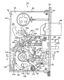
Referring now to Figure 1, a mortise lock assembly according to the present
invention is
shown and is generally designated by reference numeral 30. The lock 30
comprises a generally
rectangular box, or case 32, for housing the lock components and is adapted to
be received in a
mortise in the free, or unhinged, edge of a door. One of the side walls of the
case 32 comprises a
cap 34 which is secured to and forms a closure for the case 32.
Figure 2 shows the lock with the cap side wall 34 removed. The case 32
includes a side
wall 36 and, as seen in FIG. 2, integral top 38, bottom 40, front 42 and rear
44 walls. The front
wall 42 has openings for a latch bolt 46, a deadbolt 48, an auxiliary bolt 50
and a flush-mounted
toggle 52. A face plate 54 is secured to the front wall of the case 32 and has
openings which
correspond to the openings in the front wall 42. The latch bolt 46, deadbolt
48 and auxiliary bolt
SO are shown projecting from their respective openings in the front wall 42
and face plate 54.
An embodiment of the latch assembly for use in the mortise lock assembly of
FIG. 2 is
shown in FIG. 3 and designated generally at 56. The latch assembly 56
comprises the latch bolt
46 including a bolt head 58 and an integral latch tail 60, an anti-friction
latch 62, a coil spring 64,
a spring flange 66, a tail plate 68 and spring clip 70. The bolt head 58
includes a beveled face 72
and a slot 74. A short pin 76 extends from one side of the bolt head 58 and
into the slot 74 for
pivotally mounting the anti-friction latch 62.
The anti-friction latch 62 is shown in more detail in FIG.'S 4 and S. As seen
in FIG. 5,
one side of the anti-friction latch 62 has a groove 78 for receiving the pin
76 when the anti-
friction latch 62 is slipped into the slot 74 during manufacture. The groove
78 is closed near its
open end in a press operation to keep the anti-friction latch 62 in the bolt
head 58. A lever 77
extends from one side of the anti-friction latch and a stub 79 extends from
the opposite side.
When the latch assembly 56 is in the case (FIG. 2), the anti-friction latch 62
and the opening for
the latch bolt 46 in the front wall 42 of the case 32 are configured so that
the lever 77 engages
behind the front wall 42 while the stub 79 engages behind the face plate 54.
Returning to FIG. 3, the latch tail 60 extends from the rear of the bolt head
58. The
portion 61 of the latch tail 60 adjacent the bolt head 58 is thicker than the
free end so that the coil
spring 64 must be forced onto that portion of the latch tail thereby holding
the coil spring 64 on
the latch tail 60. The free end of the latch tail 60 is rounded and includes a
notch 80
longitudinally spaced from the free end. The tail plate 68 is generally cube-
shaped and has a
CA 02312682 2004-09-09
pass-through opening 82 for receiving the free end of the latch tail 60. The
spring clip 70 is a flat
rectangular piece defining an irregular opening 84 and having an angled tab 86
extending from
one edge of the clip 84. The tail plate 68 has a slot 88 which intersects the
tail plate opening 82
for receiving the spring clip 70. The spring clip tab 86 fits in a groove 90
in the side of the tail
plate 68.
Each side of the tail plate 68 is shown in FIGS. 6 through 11. The tail plate
68 has a
support boss 91 which sits against the case side wall 34 when the tail plate
68 is in the case 32.
The support boss 91 has a retraction surface 92. An opposed boss 94. f is in a
linear guide slot 96
in the cap side wall 14 (FIG. I) for guiding and supporting linear movement of
the tail plate 68.
Referring particularly to FIGS. 6 and 7, the tail plate 68 is shown from the
front and rear,
respectively, with the spring clip 70 in the slot 88 in the tail plate 68. The
irregular opening 84 in
the spring clip 70 aligns with the opening 82 in the tail plate 68. The
dimensions of the spring
clip 70 and the position of the slot 88 are such that the spring clip 70
partially blocks the opening
82 through the tail plate 68. The tab 86 is braced against the surface of the
groove 90 in the tail
plate 68 to bias the spring clip 70 upward to this position as seen in FIGS. 6
and 7.
An alternative embodiment of the tail plate 68a and spring clip 70a for use in
the latch
assembly 56 of the present invention is shown in FIGS. 12 through 15. In this
embodiment, the
spring clip 70a is L-shaped and has an irregular opening 84a. Two coil springs
98 are disposed
in depressions 100 (FIG. 15) in the tail plate surface on either side of the
groove 90a for biasing
the spring clip 70a upward to the position shown in FIGS. 13 and 14 partially
blocking the
opening 82a in the tail plate 68a. The other sides of the tail plate 68a are
cwrfigured the same as
seen in FIGS. 9-11.
Connection of the latch bolt 46 to the tail plate 68a and spring clip 70a is
shown in FIG.'S
16 and 17. In FIG. 16, the free end of the latch tail 60 is shown entering the
opening 82a in the
tail plate 68a. As the latch tail 60 initially enters the tail plate 68a, the
rounded end engages the
edge of the opening 84a in the spring clip 70a forcing the clip down and
compressing the springs
98. When the latch tail notch 80 passes the spring clip 70a, the springs 98
push the clip upward
so that the edge of the opening 84a in the clip engages behind the notch 80 in
the latch tail 60
securing the latch tail in the tail plate 68a. It is understood that the
embodiments of the tail plate
and spring clip in FIGS. 6 through 15 are exemplary and other structures are
possible, as long as
8
CA 02312682 2005-05-09
the function of the overall structure for releasably holding the latch tail in
the tail plate is
maintained.
As seen in FIG. 2, when the latch assembly 56 is in position in the mortise
lock assembly
30, a substantial portion of the latch bolt 46 is inside the case 32 even when
the latch bolt 46 is in
the extended position with a predetermined portion projecting beyond the front
of the case 32.
The latch tail 60 extends rearwardly from the bolt head 58 through a guide
slot formed in a boss
102 fixedly mounted between the side walls 34, 36 for guiding and supporting
the linear
reciprocal movement of the latch bolt 46. The coil spring 64 is held in
compression between the
bolt head 58 and the spring flange 66, which is urged against the boss 102,
for normally biasing
the latch bolt 46 outwardly to the extended position. A boss 103 on the spring
flange 66 fits in a
hole 104 (FIG. 1) in the cap side wall 34 for holding the flange 66 in
position.
The latch bolt 46 is moveable in the openings in the front wall 42 of the case
32 and face
plate 54 to the retracted position inside the case by operation of a latch
operator comprising
either an inside or outside knob or lever handle (not shown). In addition, the
latch bolt 46
automatically retracts when the anti-friction latch 62 and the beveled face 70
of the bolt head 58
engage the door frame upon closing of the door. Initially, the anti-friction
latch 62 engages the
door frame pivoting the anti-friction latch on the pin 76 in the bolt head 58.
As the anti-friction
latch 62 pivots, the lever 77 works against the front wall 42 of the case 32
driving the latch bolt
46 rearward into the case 32. When the latch operator is released, or the door
is in the door
frame, the coil spring 64 returns the latch bolt 46 to the extended position.
According to the present invention, the latch bolt 46 is reversible for use
with a door of
the opposite hand. In order to reverse the latch bolt 46, it is necessary to
disconnect the latch bolt
from the tail plate 68 and remove the latch bolt 46 from the lock assembly 10.
This is
accomplished by first removing the face plate 54 and then manually pushing the
latch bolt 46
into the case 32. Next, the user manually depresses the spring clip 70, which
is accessible
through the guide slot 96 in the cap side wall 34. As seen in FIG. 18, by
pressing on the spring
clip 70a with a screw driver 106 or other tool, the spring clip 70a is pushed
down against the
force of the springs 98 thereby releasing the latch tail 60 from the spring
clip 70a and tail plate
68a. When the latch bolt 46 is free of the tail plate 68a, the latch bolt 46
may be pulled through
the opening in the front wall 42 of the case 32 (FIG. 1 ), rotated
180°, inserted into the case 32
9
CA 02312682 2005-05-09
and reattached to the tail plate 68a, as described above. The slot 96 and hole
104 in the cap side
wall 34 are used for viewing to guide the latch tail 60 through the flange 66
and boss 102 and
into the opening 82a in the tail plate 68a. Because the anti-friction latch 62
can pivot and move
linearly with respect to the bolt head 58 on the pin 76, at least to the
extent of the groove 78
which has not been pressed in, the latch bolt 42 is easily manipulated during
removal and
reinsertion.
It is understood that other means for biasing the spring clip to the position
where the
spring clip partially blocks the tail plate opening are possible. For example,
the spring clip
embodiment shown in FIGS. 12 through 15 would work without the coil springs if
the clip
material was flexible enough to allow the clip to be pushed down to clear the
tail plate opening.
Thus, we do not intend ourselves to limit to the specific embodiments of the
spring clip biasing
means shown herein.
As noted above, the latch operator comprises means for retracting the latch
bolt 46
including an inside or outside knob or lever handle. The retracting means
comprises two
independent, coaxial rollback hubs 108 which are mirror images of one another.
The hubs 108
are rotatably mounted in opposed holes in the walls 34, 36 of the case 32
below the latch
assembly 56 (FIG. 2). The hub 108 which fits in the case side wall 36 is shown
in FIG. 19. The
hubs include a star-shaped aperture 110 for non-rotatable connection to inside
and outside
spindle drives (not shown) connected to the knobs or lever handles for
rotating the hubs 108.
Each hub 108 has an upper rollback surface 112 which faces the rear wall 44 of
the case 32, a
forwardly extending boss 114 and downwardly depending legs 116. As seen in
FIG. 2, the legs
116 engage an L-shaped bracket 118 attached to the bottom of the case 32 for
preventing
clockwise rotation (as seen in FIG. 2) of the hubs 108. Two torsion springs
120 are mounted on
a transverse pin 122 adjacent to the front of each hub 108. An end of each
spring 120 fits in a
notch 124 (FIG. 18) in the hubs 108 for restoring the hubs to the neutral or
home position when
the knob or handle is released. It is understood that, as an alternative, the
mortise lock assembly
may have a single hub to which both the inside and outside spindle drives are
connected.
The retracting means also includes a retractor shoe 126 and a hub lever 128.
The shoe
126 is mounted for linear movement within the case 32 and has a forwardly
facing bearing
surface 130 for engaging the rollback surfaces 112 of the hubs 108 and a
rearwardly facing
CA 02312682 2000-06-28
bearing surface 132. In this arrangement, the shoe 126 moves linearly rearward
in response to
counterclockwise rotation, as seen in FIG.'s 2 and 24, of either of the
rollback hubs 108. A
torsion spring 134 acts between the rear wall 44 and the retractor shoe 126 to
urge the shoe
toward engagement with the roll back hubs 108. .
The hub lever 128 comprises a generally flat, L-shaped lever disposed within
the case 32
against the case side wall 36. The hub lever 128 is pivotally supported on a
pin 129 at its lower
forward leg 136 below and in front of the hubs 108. The upper leg 138 of the
hub lever 128
extends upwardly to the rear of the hubs 108 and has a first laterally
projecting tab 139 adjacent
the rearward bearing surface 132 of the shoe 126. A portion of the upper leg
of 138 of the hub
lever 128 is adjacent to the retraction surface 92 of the tail plate 68. A
torsion spring 143 acts
between the rear wall 44 and the first tab 139 to bias the hub lever 128 into
operative engagement
with the retractor shoe 126.
As seen in FIG. 24, the latch bolt 46 is retracted by rotating one of the
rollback hubs 108.
Rotation of the rollback hub 108 causes the rollback surface 112 to engage the-
bearing surface
130 of the retractor shoe 126 moving the shoe linearly rearward. The shoe's
rearward bearing
surface 132 engages the first hub lever tab 139 to pivot the hub lever 128 in
a counterclockwise
direction as seen in FIG. 24. The portion of the upper leg of 13 8 of the hub
lever 128 acts
against the retraction surface 92 of the tail plate 68 to move the tail plate
and connected latch bolt
46 to the retracted position.
The present invention is also concerned with the locking mechanism (FIG. 2)
for
selectively securing one or both of the retractor hubs 108 from rotation. The
locking mechanism
comprises an elongated slide plate 142 and the toggle 52. Referring to Fig.
20, the rearward end
144 of the slide plate 142 has two slots 146 for receiving a portion of the
hubs 108 adjacent the
respective bosses 114. Both ends 144,145 of the slide plate 142 have opposed
lateral tabs 148;
149 which ride in corresponding slots 150 in the side walls 34, 36 of the case
for guiding and
supporting linear movement of the slide plate 142 relative to the hubs 108.
Each rear plate tab
148 has a transverse hole 152 which opens into the slots 146. The holes 152
are preferably
threaded for receiving a blocking screw 154. The screw 154 is sufficiently
long so that when the
screw 154 is threaded into the tab 148 the screw extends into the slot 146.
CA 02312682 2005-05-09
The slide plate 142 is cooperatively linked to the toggle 52 which is
accessible through
the opening in the front wall 42 and face plate 54. Manipulation of the toggle
52 linearly
reciprocates the slide plate 142 relative to the hubs 108 between an unlocked
position (FIGS. 20
and 21) and a locked position (FIGS. 22 and 23). The locking mechanism is
moved to the locked
position by depressing the upper end of the toggle 52 thereby moving the slide
plate 142 so that
the rearward end 144 is positioned adjacent the hubs 108. When the locking
mechanism is in the
locked position, the screw 154 is in the path of the boss 114 on one of the
retractor hubs 108
thereby preventing rotation of the hub 108. As noted above, the hub 108
preferably affected by
the locking mechanism is on the outside of the door. Therefore, the screw 154
is preferably
placed in the rear slide plate tab 148 corresponding to the outside hub 108 so
as to prevent
rotation of the outside hub and retraction of the latch bolt 46 from the
outside when the lock is
locked. The inside hub 108 can still turn to permit retraction of the latch
bolt 46 since the hub
boss 114 passes freely through the open slot 146 in the slide plate 142. If
the mortise lock is
reversed for installation in a door of the opposite hand, the screw 154 is
simply moved to the
opposite rear tab 148. Of course, in mortise locks using a single hub, the
screw prevents rotation
of both operators. Similarly, in the illustrated embodiment, a second stop
screw can be used with
the same effect. The locking mechanism is unlocked by depressing the lower end
of the toggle
52 thereby moving the slide toward the front wall 42 of the case 32 and away
from the hubs 108
(FIGS. 20 and 21 ).
Preferably, the mortise lock assembly includes the deadbolt 48 and the
auxiliary bolt 50.
The deadbolt 48 is selectively moved between an extended position and
retracted position by
operation of a key cylinder or thumb turn (not shown) in a conventional
manner. The cylinder
and thumb turn rotate a deadbolt lever 156 which engages the sides of a slot
158 in the rearward
end 160 of the deadbolt 48 for extending or retracting the deadbolt. The upper
leg 138 of the hub
lever 128 has a second laterally projecting tab 162 for engaging the deadbolt
lever 156 when the
deadbolt 48 is in the extended position for retracting the deadbolt along with
the latch bolt 46 in
response to rotation of either hub 108 (FIG. 24).
A rotating stop lever 164 is provided for functionally connecting the deadbolt
lever 156
and locking mechanism (FIG. 2). The lower end 166 of the stop lever 164 is
positioned in a slot
168 in the slide plate 142 and the upper end 170 is arranged in the path of
the deadbolt lever 156.
12
CA 02312682 2000-06-28
When the deadbolt 48 is moved from the retracted position to the extended
position the deadbolt
lever 156 engages the upper end portion 170 of the stop lever 164 to rotate
the lever in a
clockwise direction (as seen in FIG. 2) and move the locking mechanism,
including the side plate
142 and toggle 52, to the locked position. Thus, the locking mechanism
automatically moves to
the locked position when the deadbolt 48 is moved to the extended position.
The locking
mechanism remains in this position, even when the deadbolt 48 is retracted by
operation of one
of the hubs 108 (FIG. 24), until the toggle 52 is actuated to move the slide
plate 142 away from
the hubs 108.
Means for deadlocking the latch bolt 46 in the extended position is also
provided (FIG.
2). The deadlocking means 172 comprises the auxiliary bolt 50, a deadlocking
lever 174 and an
auxiliary latch lever 176. When the door is closed, the auxiliary bolt 50 is
depressed by the door
frame which allows the deadlocking lever 174 to pivot in a counterclockwise
direction under the
biasing force of a compression spring 178 to a position where the deadlocking
lever prevents
manual depression of the latch bolt 46. The deadbolt 48 also has a shoulder
180 which is
adjacent the rear surface of the bolt head 58 when the deadbolt is extended
also for preventing
depression of the latch bolt 46.
The previously described embodiments of the present invention have many
advantages,
including the provision of a reversible mortise lock which cannot be tampered
with after
installation. Moreover, because the latch bolt reversal relies on removal of
the entire latch bolt
from the case rather than partial removal, the bolt head can be as long as is
practical thereby
providing greater strength and security for the lock. The mortise lock
incorporating the new
latch assembly and locking mechanism is easily modified from outside of the
lock casing with a
screw driver for use with either a right-hand door or a left-hand door.' In
either arrangement, the
latch operators are operable to open the door when the lock is unlocked. When
the lock is
locked, rotation of the outside latch operator is prevented, whereas the
inside latch operator is
still operable to open the door. With the addition of another blocking screw,
the inside latch
operator can also be locked against rotation.
Although the present invention has been shown and described in considerable
detail with
respect to only a few exemplary embodiments thereof, it should be understood
by those skilled in
the art that we do not intend to limit the invention to the embodiments since
various
~3
CA 02312682 2000-06-28
modifications, omissions and additions may be made to the disclosed
embodiments without
materially departing from the novel teachings and advantages of the invention,
particularly in
light of the foregoing teachings. For example, a single rollback hub can
replace the two,
independent hubs so that the locking mechanism affects both the inside and
outside latch
operators. Accordingly, we intend to cover all such modifications, oriiission,
additions and
equivalents as may be included within the spirit and scope of the invention as
defined by the
following claims. In the claims, means-plus-function clauses are intended to
cover the structures
described herein as performing the recited function and not only structural
equivalents but also
equivalent structures. Thus, although a nail and a screw may not be structural
equivalents in that
a nail employs a cylindrical surface to secure wooden parts together, whereas
a screw employs a
helical surface, in the environment of fastening wooden parts, a nail and a
screw may be
equivalent structures.