Note: Descriptions are shown in the official language in which they were submitted.
CA 02312852 2000-06-O1
. ; , , ,
1
IMPROVEMENTS IN AND RELATING TO A WAVE-POWERED
PRIME MOVER
The present invention relates to wave-powered prime movers of the type adapted
to extract
energy primarily from ocean swell.
European Patent Specification No. 0 365 325-B discloses a wave powered prime
mover for
harnessing primarily the energy of the ocean swell. The prime mover comprises
two
movable pontoons spaced apart by a floating inertial body. Each pontoon is
independently
1o movable relative to the inertial body to activate a pump. The inertial body
is provided with
an inertia plate for maintaining the inertial body substantially stationary in
the water
irrespective of the prevailing wave frequency and/or amplitude. The inertia
plate is
connected to the inertial body by at least one shaft and is movable relative
to the inertial
body. When the prime mover is being towed through water, the inertia plate is
raised to
~5 decrease resistance. Then, when the prime mover is in its operational
position, the plate is
lowered into the water to keep the inertial body substantially stationary.
In general, energy derived from such wave-powered prime movers is provided as
a low
frequency oscillating waveform. The energy must be converted to a useful
frequency
2o and/or type before it can be utilised. However, standard techniques for
converting energy
from a low frequency waveform to a high frequency waveform are inherently
inefficient.
US-A-4, 023,515 discloses a floating wave powered pump having a plurality of
floats
connected to a floating platform by a double acting piston pump to gather
energy derived
25 from the relative movement between the float and the platform. Seawater is
pumped by
the device.
US-A-4, 105, 368 discloses a floating wave powered pump having a primary float
surrounded by satellite floats which can move relative to one another. The
motion of the
3o floats is converted by hydraulic fluid into pressure accumulators and the
stored pressure
can be selectively tapped as a source of power.
CA 02312852 2000-06-O1
2
US-A-781,023 teaches a wave driven generation system in which a plurality of
buoyant
raft energy absorber units are connected to a stable mooring assembly. Energy
collected
by the relative movement between the rafts and the mooring assembly is
converted into
mechanical, hydraulic and/or electrical energy. Accumulators are used to
control and
store pressure.
DE-A-2 921 381 likewise teaches a device in which movable pontoons are
connected to a
platform and a hydraulic pump is used to pressurise oil. A pressure chamber is
provided
for storing and controlling the pressure for delivery to a turbine or
hydraulic motor.
It is an obj ect of the present invention to seek to alleviate the
disadvantages associated with
prior art wave-powered prime movers and to provide an improved power take-off
and
damping mechanism for such a device.
Accordingly, the present invention provides a power take-off and damping
mechanism for
a wave-powered prime mover of the type having at least two pontoons which move
relative
to one another to do work as defined in the appended claims.
The prime mover may be anchored to underlying seabed or otherwise secured to
moor it.
2o In use for generating energy, the prime mover in its totality will be
moored, but the
mooring must be effected in such a way as to enable the inertial body to have
some
freedom to heave, sway and/or oscillate within the confines permitted by the
inertia plate.
In a preferred arrangement, the present invention provides a wave-powered
prime mover of
the type comprising two movable pontoons spaced apart by a floating inertial
body, each
pontoon being independently movable relative to the inertial body to activate
a pump, the
inertial body having an inertia plate operable to maintain the inertial body
substantially
stationary in water and a power take-off and damping mechanism, the mechanism
comprising:
~,P,~'NBFD SHEET
CA 02312852 2000-06-O1
3
means for converting the motion of the pontoons into hydraulic pressure
energy, said
means comprising at least one linear oil pump which transfers energy across a
transfer
barrier to sea water;
means for rectifying the pressure energy into a uni-directional form;
control means for regulating the pressure energy; and
a feedback means for varying the damping parameters of a damping means.
The means for converting the motion of the pontoons into pressure energy
comprises at
least one linear hydraulic pump connected between each movable pontoon and the
inertial
body.
~5 The means for rectifying the pressure energy comprises a plurality of non-
return valves in
conjunction with at least one pressure accumulator.
The inertia plate is preferably disposed at one end of a shaft, the other end
of which is
connected to the inertial body. Preferably, the shaft is movable to vary the
distance
between the plate and the inertial body.
The damping parameters of the prime mover are affected by the both depth of
the inertia
plate in the water and the freedom of movement of the pontoons with respect to
the inertial
body. The linear hydraulic pumps directly affect the freedom of movement of
the
oscillating pontoons.
The feedback means comprises a plurality of valves adjustable to regulate back-
pressure in
the or each linear hydraulic pump thereby varying the damping parameters of
the relative
motion between the inertial body and each independently movable pontoon.
Preferably, the damping parameters are varied by altering the back-pressure to
the or each
linear pump.
AMENDED SN'E~f
CA 02312852 2000-06-O1
4
A hydraulic circuit is provided to extract hydraulic pressure energy from the
relative motion of the
oscillating pontoons. The circuit comprises at least one linear hydraulic pump
connectable between
the inertial body and a pontoon, and a pressure manifold in which hydraulic
pressure energy
transferred from the pump along hydraulic lines is stored when the pump is
moved between an
extended position and a retracted position.
Preferably, the circuit includes, for each pump, a first accumulator for
accepting hydraulic pressure
energy when the pump is forced from the extended position to the retracted
position, a second
accumulator for accepting hydraulic pressure energy when the pump is forced
from the retracted
position to the extended position, and a plurality of check valves to ensure
energy derived from the
pump is diverted to the pressure manifold.
The hydraulic circuit is preferably split into two portions, one utilising a
stored hydraulic fluid such
as oil and the other utilising the water on which the prime mover floats, the
two portions being
isolated by a transfer barrier disposed in each accumulator.
A plurality of pumps are connectable to the pressure manifold.
The hydraulic circuit is duplicated to extract energy from the relative motion
of the inertial body
and the other pontoon.
The or each pressure manifold provides pressurised fluid (preferably water)
for activating a turbine
to extract electrical energy or for supplying high pressure water to a reverse
osmosis plant to
prepare drinking water from salt water.
The invention will now be described more particularly with reference to the
accompanying
drawings which show, by way of example only, one embodiment of power take-off
and damping
mechanism according to the invention. In the drawings:
Figure 1 is a side elevation of a wave-powered prime mover;
Figure 2 is a plan view of the prime mover;
Figures 3a to 3c are a side elevation, an end elevation and a plan view,
respectively, of the inertial
body of the prime mover, showing in detail the hydraulic circuit which
comprises the power take
off and damping mechanism;
Ar.~~~IDED St~E~T
CA 02312852 2000-06-O1
4.
WO 99/28622 PCT/IE98/00099
Figure 4 is a schematic diagram of the hydraulic circuit for one linear pwonp;
and
Figure 5 is a perspective schernatie view of a power transfer meettanism.
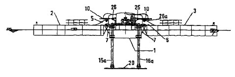
5 Referring now to the drawings and initially to Figures 1 and 2, the prime
mover includes a
tloatxng inertial body or barge 1 having independently pivotally connected
floating
pontoons, 2.3 attached thereto. Each pontoon 2,3 loos hiunges 5 for correcting
to
corresponding hinges 7 of tine inertial body. Movement of a pontoon 2,3
relative to the
inertial body 1 under the in.flueztce of the ocean swell ox waves operates
pumps 10 provided
o between the inertial body 1 and the respective pontoons 2,3.
The width of the pontoons 2,3 may be selected to suit the desired output
requirement,
~typircal wave frequency and/or amplitude at any chosen location, preferably
..to maxizztise
energy output The pontoons 2.3 are placed on opposite sides of the inertial
body 1. In use
~ s the prime mover is anchored or otherwise tethered to avoid drift and due
to the orientation
of. the pontoons .with respect to the inertial body, that is to say, with
their longitudinal axes
being mutually parallel, the prime mover orients itself at rigl'tt angles to
the wave or swell
direction, resulting in maximum energy extraction by tb.e independently
operating
pontoons 2,3 which move relative to the inertial body. The tethering does not
affect the
zo relarive positio~a of Llxe inertial body in the water and does not affect
ability of the damping
ttsscmbly (described below) to maintain it substantially vertically stationery
in the water.
The inertial body 1 is provided with an assembly for maintaining the body 1
substantially
stationary in the water when in use. The assembly comprises two pairs of
spaced apart legs
25 15a, 156, 16a,16b which are mutually parallel_ Each pair of legs are
connected to the
inertial body at one end and are connected to an inertia plate 20 at their
lower ends- The
assembly may be raised or lowered relative to the inertial body by means of
winches and/or
hydraulic operating mesas (not shown). The optimum depth of the plate in the
water is
approximately 9 metres.
CA 02312852 2000-06-O1
WO 99/28622 pCT/(E98/00099
G
Figures 3a to 3c are detailed views of the inertial body I. Tlae inertial body
1 is a
substantially hollow vessel having at least two hinge couplings 24 on each
side for
connecting to the pontoons 2,3. Linkages 26 are also provided for linear pumps
10 which .1
are fixed between said linkages 26 and cozxesponding linkages 26a on the
pontoons 2,3.
The pumps 10 are operable to extend and contract with the relative movement
between the
inertial body 1 and the respective pontoons 2,3 to generate hydraulic pressure
in a
hydraulic.circuit w]~ich is shown in detail in Figures ct anal 5.
The hydraulic circuit is provided to extract energy frorx~ waves or ocean
swell by
o mataipulating hydraulic pressure energy from the relative motion of the
movable pontoons
2,3. Onc hydraulic circuit is provided for each pontoon 2,3. Each Y~ydraulie
circuit
comprises at least two pumps 10, first accumulators 32 for accepting hydraulic
pressure
exaergy when each pump 10 is forced from an extended position (position A,
Figure 4) to a
retracted position (position B. Figure 4), second accumulators 34 for
accepting hydraulic
pressure energy when each pump 10 is forced from the retracted position to the
extended
positionf a pressure manifold 35 and a series of foot valves 37 and check
valves.39 to
ensure such energy is stored in the manifold 35. In one poztiozr of the
circuit, a stored
hydraulic fluid such as oil is used to transfer energy and in the other
poztion of the circuit,
sea water is used as tb~e hydraulic medium. The two fluids axe separated by s
transfer
2o barrier 40 disposed in each accumulator 32,34, Each accumulator comprises a
28 litre, 345
bar container. In a particularly useful arrangement, each pzizne mover has
three pumps
forward and two purnps aft, and these znay be divided between two hydraulic
circuits.
As detailed iri Figures 4 and 5, when the linear pump 10 is driven by the
movement of a
pontoon, the action displaces up to 5 gallons (22.74 litres). Sea water is
drawn up into the
first accumulator 32 through a unidirectional foot valve 37 by the negative
pressure
(vacuum) generated by moving the pump from A to B. I~ydraulic oiI is forced
out of the
pump into the second accumulator 34, forcing sea water on the other side of
the transfer
barrier 40 through a check valve into the pressure manifold 35 which is rated
at 300 b:~r.
3o Conversely, when the pump 10- is driven from B to A, sea water is drawn up
front the
opposite foot valve 37 into the second aceumuiator 34 and hydraulic pressure
energy forces
CA 02312852 2000-06-O1
w0 99/28622 Pc'WrE98/oo099
7
sea water in the i'lrst accumulator 32 thzouglr its respective check value 39
into the
z~aanz;fold 35. From the reciprocating motion of the pump 10, pressure energy
is stored in
the manifold 35 to be utilised in a regulated mauaner. Pressurised sea water
can be released
controllably to drive turbines for convening the pressure energy to electrical
energy or can
s be u5cd directly nn a reverse osmosis plant for desalinating the water.
The pressure energy derived cats also be applied to altering the damping
characteristics of
the prime mover by varying the relative freedom of movement of the pontoons
z,3 with
respect to the inertial body 1. By applying back-pressure to the pumps 10, the
overall
stiffness of the prime mover is increased. This stiffness in turn varies the
damping
parameters of the structure and alters the overall energy efficiency of the
prune mover. By
actively controlling back-pressure to the pumps 10, using conventional control
techniques,
the energy efficiency and damping gazsnneters of the prime mover can be
adjusted
according to the prevailing weather, wave height and frequency and to the
ocean swell.
'The present invention has particular .. application in island communities and
coastal
communities where drinking water is scarce. The invention is easily adaptable
for use for
power generation or can be adapted to directly produce drinking water. The
invention uses
s rniniznal number of moving parts and is robust, decreasing the overall cost
and
maintenance cost of wave-powered prime movers. The facility to vary back-
pressure in the
hydraulic system allows for variable damping. Back-pressure can be controlled
using a
valve controlled feedback circuit which is operable using a remote control
means. The
prime mover can be used independently or can be linked to a plurality of other
prime
movers remotely controlled using standard control technology and telemetry.
It will of course be understand that the present invention is not limited to
the specific
details described herein, which are given by way of example only and that
various
modifications and alterations are possible within the scope of the invention,
as defined by
the appended claims.