Note: Descriptions are shown in the official language in which they were submitted.
CA 02312915 2004-08-24
1
AUTOMATIC LIQUID INJECTIaN SYSTEM AND METHOD
Field of the invention
The present invention concerns the administration by
injection to patients of liquid compositions for
therapeutic or diagnostic purposes. It more particularly
concerns a power assisted method and device for
controllably dispensing a liquid medicament or
diagnostically active contrast agent, the homogeneity of
which is preserved throughout delivery. Typically, the
contrast agent is an aqueous suspension of gas filled
microvesicles, namely microbubbles bounded by a surfactant
stabilized gas/liquid interface, or microballoons bounded
by a tangible material envelope.
Background Art
Power injectors and mechanically assisted infusion
systems for controllably dispensing therapeutically active
medications are well known in the art. Typically, such
devices include an automatic injector for syringes
containing an injectable liquid and a plunger or piston
movable within the barrel of the syringe to expel said
liquid through a' tip thereof and injecting into a patient
via a tubing connected to an injecting needle or catheter.
For controlling the injections parameters, the plunger is
driven by means of an electromechanical arrangement
organised to push the plunger at a desired rate,
continuously or at chosen intervals, so that the amount of
medication is delivered to the patient's body under
strictly determined conditions. For instance, in the case
of intravenous dispensing contrast agent formulations for
diagnostic purposes (X-ray, MRI or ultrasound), the rate
and the mode of injection can be accurately controlled to
match the requirements of the imaging methods and detector
systems used to investigate the circulation or a specific
organ in the body. Typical automated injection devices are
illustrated and described in US-5,176,646,
Although the automated injectors known are highly
4U sophisticated instruments capable of mastering most
CA 02312915 2000-OS-30
WO 99/27981 PCT/IB98/01938
2
injection problems experienced in practice, there remains
at least one variable factor not yet under control. Indeed
the known power injectors have no control of the
homogeneity of the liquid stored within the syringe barrel
during the course of its application. This kind of problem
is of course non-existent with "true solutions" (i.e.
solutions to the molecular level ) since in this case no
concentration change can occur in the course of time; it
however may become important when the injectable
formulation is a suspension or dispersion of active
particles which tend to settle, coalesce or segregate with
time in the syringe. Indeed, even some modest separation of
the particles by gravity or otherwise from the carrier
liquid in the course of administration of the formulation
may have very important influence on reproducibility and
reliability of the tests. Hence, in this case, a method and
means to keep the syringe content homogeneous during
injection is highly desirable. The present method and
device constitute a very effective solution to the
aforediscussed problem.
Su~,axy of the invention
Briefly stated, in order to secure homogeneity of a
liquid suspension of particles within the barrel of an
injector device, the invention provides a method and means
whereby the particles are kept under sufficient agitation
so as not to settle, segregate or agglomerate in the
carrier liquid. This may involve acting on the carrier
liquid itself, i.e. on the bulk of the suspension, or may
involve acting only on the particles ( in this case, one
would expect the moving particles to impart motion to the
carrier liquid by viscous friction). The agitation means
may be provided within the syringe or in some cases outside
thereof; for instance with magnetic particles, the
particles can be subjected to an external variable magnetic
field, the oscillation or rotation of which will set them
into motion, the moving particles then acting on the
carrier liquid and keeping the suspension homogeneous.
CA 02312915 2004-08-24
3
In the case of particles not sensitive to external
fields, mechanical agitation is provided to the extent that
it is sufficient to keep the suspension homogeneous but
insufficient to break or damage the particles or disturb
their distribution. For this, the syringe barrel is
subjected to motion, said motion being continuous or
discontinuous, regular or irregular; the motion can
possibly have a shaking, rocking or oscillating effect on
the syringe. The frequency, intensity and rate of the
motion is such that it will not interfere with the control
of delivery parameters of the suspension_
According to one aspect of the present invention,
there is provided use of an injector system comprising a
syringe containing a suspension of microparticles
homogeneously distributed in an aqueous liquid carrier and
a power driven piston adapted for injecting the suspension
into a patient, wherein, by subjecting the suspension in
the syringe to a rotation or rocking motion, which prevents
segregation of the microparticles by gravity or buoyancy
without damaging the particles or disturbing their
distribution, the suspension maintains homogeneous.
According to a further aspect of the present
invention, there is provided an injector system for
administering to patients by injection or infusion a
suspension of microparticles in an aqueous liquid carrier,
the system comprising a syringe whose barrel contains the
suspension, and automatic electromechanical power means
controllably acting on the syringe to inject the suspension
into a patient, wherein the injector system further
comprises means for agitating the microparticles in the
suspension, the agitation keeping the suspension homogenous
by preventing segregation of the particles by gravity or
CA 02312915 2004-08-24
3a
buoyancy without damaging the particles or disturbing their
distribution.
According to another aspect of the present invention,
there is provided use of an injector system as described
herein in imaging of organs, blood vessels and tissues of a
mammalian.
The embodiments disclosed below in connection with the
annexed drawings provides very effective means to keep the
syringe content under sufficient agitation to secure
injection of a homogeneous therapeutic or diagnostic liquid
compositions into a patient_
Brief description of the drawings
Fig. 1 is a schematic view in perspective of a device
for agitating a liquid within the syringe of a power driven
automatic injector system of the invention_
Fig. 2 is a graph illustrating the homogeneity
variations in a suspension of microbubbles contained in a
syringe, the latter being either still or subjected to
motion according to the invention.
Fig. 3 is a graph illustrating the gas volume and in
vitro intensity of samples with and without treatment
according tv the invention.
Fig. 4a is a schematic view in perspective of another
device for agitating a liquid within the syringe of a power
driven automatic injector system of the invention. In this
embodiment, the syringe is held by a supporting bracket,
the latter being driven into motion by a motor.
Fig 4b is .a schematical sectional view of the motor
driving means of the embodiment of Fig 4a.
CA 02312915 2005-04-04
4
Detailed description of the invention
The device represented schematically in Fig. 1
comprises a series of co-operating elements mounted on a
board 1. Such schematic representation of the present
S device is only for clarity and better understanding of the
device's operation. Obviously, in its actual commercial
construction, the device is in the form of a much more
compact and sophisticated apparatus, for instance in the
form of an instrument like the Perfusorc9 fm of the Firm
BRAUN Meslungen AG, D-34209, Meslungen, Germany (displayed
in Publication B.03.01_95 No 0879 0744), or like, the
apparatuses disclosed in US-A-4,652,260 and US-A-5.176.502.
The present device comprises the following working
components: a syringe 2 shown in an uplifted position, an
automatic power driving unit 3 for acting on the syringe, a
pair of syringe motioning units 4 for liquid agitation, and
a control box 14 for controlling operation of the units 4.
The syringe 2 has a barrel 5, a plunger 6 sliding in
the barrel and a tip connector 7 linked to a tubing 8, the
latter leading to an injection needle 9. The needle 9 is
for injecting an administrable liquid into the tissues or
the circulation of a patient.
The power driving unit 3 has an eiectromechanically
controlled pusher rod 10 for acting on the rear end 11 of
the syringe plunger, and a control knob 12 for setting the
automatic driving parameters that will marshal the action
of the rod 10.
Each unit 4 is equipped with two rollers 13,
themselves driven into rotation by electric motors within
the units and not represented in the drawing. The rotation
of the rollers 13 is governed by means of a box 14 via lead
wires 15 connected to said motors.
In operation, an injectable carrier liquid with
particles (e.g. gas-filled microballoons) in suspension is
introduced into the barrel 5 of the syringe 2 through the
tip 7, this being consecutive to the retraction (manual or
mechanical) of the plunger 6, so that an adequate pumping
CA 02312915 2000-OS-30
WO 99/27981 PCT/IB98/01938
action is provided. Then the syringe is placed on the
rollers 13, so that the flange 16 thereof abuts the
roller's edge 17, this being for retaining the syringe in
its relative position against unwanted longitudinal
5 translation. In this situation, the pushing rod 10 of the
driving unit 3 couples with the plunger's end 11, so that
any forward displacement of the rod 10 is transferred to
the plunger with consequent expelling of the liquid toward
the needle 9 for injection.
During injection, the rollers will alternately rotate
the syringe a certain angle in one direction, say 30°, 60°,
90°, 180°, 270° or 360° and then, reciprocably, in
th,~
opposite direction. This balancing motion, which may be
carried out in a stepwise manner, will move the liquid
carrier to such an extent that any separation or
segregation of the particles is hindered. This is very
efficient for instance in the case of suspensions of gas-
filled microbubbles used in echography since there is
always a bubble size distribution in such suspensions, the
larger bubbles tending tv rise faster than the smaller ones
by buoyancy. In a variant, the syringe can be made to
rotate in one direction only, provided that the connector
tip 7 thereof is made to freely rotate in order to prevent
distortion of the tubing 8. Normally, the rate of rotation
impressed by the rollers 13 is from about 0.5 to 200 rpm
depending upon the suspension viscosity. This rate should
be sufficient to keep the particles in homogeneous
suspension but insufficient to break the particles or
disturb their distribution in the carrier liquid. If
necessary, in the case of more viscous suspensions, an
additional vibrational motion of a few Hz to a few hundreds
of Hz can be applied to the syringe by means of a pitch-
fork or pitch-pipe. It should be mentioned that at very
high rotation rates (e.g. 1, 000 rpm or more) the radial
speed may become dominant which will result in axial
concentration of the microbubbles in the middle of the
syringe. Rotational speeds at which the radial component
becomes important are to be avoided as under such
CA 02312915 2000-OS-30
WO 99/27981 PCTlIB98/01938
6
conditions the suspension will become non-homogeneous
again. This is clearly undesired.
In a variant, the unit 4 can have the form of a
closable housing equipped with fixed syringe retaining
means, i.e. other than the rollers edges 17 and, possibly
if required, pressure resisting means (like a pressure
mantle or jacket) in case the suspension is viscous and
exerts undue pressure efforts to the syringe barrel. Also
the syringe components can be made of moulded plastic
(disposable syringes) and the barrel external surface
provided with an integrally moulded relief pattern mating
with corresponding pattern on the rol~.er's surface, so that
positive grip drive of the syringe is ensured.
Also, the rod 10 and the plunger 6 can be made
integral with each other so that filling of the syringe can
be controlled by the power unit 3, the pumping action then
resulting from a backward displacement of rod 10.
The power unit per se is standard and its nature and
operation well known to the skilled person. Embodiments
thereof are disclosed in the cited references and also in
US-A-5,456,670. The power unit usually contains an
electrically powered and controlled helical screw means for
mechanically advancing or retracting rod 10 continuously or
intermittently, so that the liquid in the syringe can be
dispensed continuously or by increments. The various
parameters ruling said motions of the syringe piston can be
monitored and adjusted by the control 12 and possible other
control means not represented in the drawing. Means of unit
3 also ensure that such delivery parameters can be
monitored and recorded for display. An instant stop switch
(not shown) may also exist, in case the operation of the
system should be suddenly interrupted due to a problem with
the patient or otherwise.
It should be incidentally noted that although the
present embodiment involves rocking the syringe only, one
may also consider a modification involving a back and forth
rotation of the pumping ensemble, this being achieved by
CA 02312915 2005-04-04
7
well known mechanical means adapted to support said pumping
ensemble and to impart motion thereto.
Furthermore, although the present embodiment involves
motion around the longitudinal axis, a variant may include
rocking the syringe about a transversal axis.
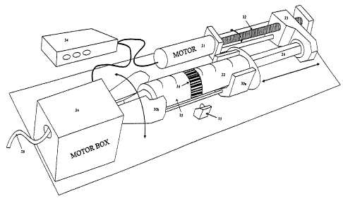
A second device embodiment illustrated schematically
in Fig 4a and 4b comprises a syringe 22 with a a barrel 25
supported in a rotatable fashion by a bracket 30a-30b and a
plunger 26 sliding in the barrel whose displacement therein
is controlled by a a power driven unit 23 capable of moving
forward and backward in engagement with the back pusher end
of the plunger 25. The device also comprises a motor driven
unit. 24 encompassing a portion 30b of the supporting
bracket, the latter being rotated through gears 37, as
better shown on Fig, 4b, for agitation of a liquid
suspension~in the syringe barrel. The longitudinal forward
or backward displacement of the unit 23 (acting on the
plunger 26) is effected via a motor 31 which rotates a
screw-bar 32, the latter engaging with a matching threaded
portion (not shown) within the unit 23. The device further
comprises an electronically computerized control box 34 for
controlling operation of the units 23 (via motor 31) and
24, and for processing the signals from a laser detector 35
designed to read an identifying mark 36 on the syringe;
this mark is for preventing errors in the selection of the
syringe, especially if the syringe is of the prefilled
type. The code of the mark can be according to standard bar
codes. Note in this regard that since the syringe barrel is
set into rotation in the present device, one can use a
fixed detector instead of a mobile one which is
advantageous designwise. By counting and recording via box
29 the number of turns of the screw bar 32, the position of
the unit 23 (and consequently of the plunger 26) can be
monitored and regulated at will_ The control box 34 can of
course comprise further monitoring and visualizing means
(not shown) to optically display and appropriately regulate
the various parameters involved in operation of the device.
As in the previous embodiment, the syringe has a tip 27
CA 02312915 2000-OS-30
WO 99/27981 PCT/IB98/01938
8
for connecting to a liquid dispensing tubing 28, the
latter leading to means for injecting an administrable
liquid into a patient.
The operation of the present device is very similar to
that of the earlier embodiment and hence needs not be
discussed further at length. Suffice to say that it may
also comprise security means intended to automatically
interrupt the operation in case troubles develop with the
patient or otherwise during injection. For instance, the
pressure in the syringe barrel can be monitored by
registering the force required to push the plunger, this
being via the power absorbed by the driving motor 31. A
sudden surge, for instance a rapid increase of current in
said motor can trigger via the control unit 34 an emergency
stop of the device. Alternatively, this effect could also
be detected according to usual means by a strain gauge
installed in the drive 23.
As already said, the particles of the suspensions in
this invention may be of various kinds and involve for
instance microspheres containing entrapped air or other
gases used in echography. These microspheres may be bounded
by a liquid/gas interface (microbubbles), or they may have
a tangible membrane envelope of for instance synthetic
polylactides or natural polymer like denatured protein such
as albumin (microballoons). The carrier liquid for the
microbubble suspensions comprises surfactants, preferably
saturated phospholipids in laminar or lamellar form such as
diacylphosphatidyl derivatives in which the acyl group is a
C16 or higher fatty acid residue.
The gases used in the microbubbles or microballoons
are pure gases or gas mixtures including at least one
physiologically acceptable halogenated gas. This
halogenated gas is preferably selected among CF4, C2F6,
C3Fg, C4Fg, C4Flp, C5F12, C6F14 or SF6. The gas mixtures can
also contain gases such as air, oxygen, nitrogen, helium,
xenon or carbon dioxide. In fact in a number of cases
microbubbles or microballoons will contain mixtures of
CA 02312915 2000-OS-30
WO 99/27981 PCT/IB98/01938
9
nitrogen or air with at least one perfluorinated gas in
proportions which may vary between 2 and 99~.
In the microballoons the membrane is made from a
biodegradable material such as biodegradable polymers,
solid triglycerides or proteins and are preferably selected
from the polymers of polylactic or polyglycolic acid and
their copolymers, denatured serum albumin, denatured
haemoglobin, lower alkyl polycyanoacrylates, and esters of
polyglutamic and polyaspartic acid, tripalmitin or
tristearin, etc. In an embodiment, the microballoons are
filled with C3Fg and the material envelope is made of
albumin.
Homogeneity of suspensions of microballoons whose
membrane is made of saturated triglycerides such as
tripalmitin, trimyristin or tristearin and their mixtures
with other tri- or di- glycerides, fatty acids or polymers
is particularly interesting as those are used for
delivering active ingredients to specific sites within the
body. Homogeneity of suspensions of such microballoons has
been effectively maintained using the method and the device
of the invention.
Other particles whose density is different from
that of the carrier liquid may include liposomes filled
with iodinated X-ray opacifiers such as iomeprol,
iopamidol, iopentol, iohexol, metrizamide, iopromide,
iogulamide, iosimide or ioversol or, for instance, coated
and uncoated magnetic particles which tend to precipitate
in saline or other carriers.
The present injector system can be used in
imaging organs, blood vessels and tissues of mammalians,
e.g. the ultrasonic imaging of the heart, the liver or
spleen, the brain, the kidneys, the blood vessels, etc.
The invention is further illustrated by the
following Examples:
Examr~le 1
A solution of gas filled microbubbles stabilised
by a phospholipids interface was prepared according to
CA 02312915 2000-OS-30
WO 99/27981 PCT/IB98/01938
Example 1 of US 5,445,813. The dry matter concentration was
5 mg/ml in a saline solution (0.9~ NaCl). Typically, the
bubble size distribution extended from 0.2 to 15 [lm. The
concentration of bubbles between 2 and 5 ~tm was 5x10
5 microbubble/ml.
The solution was transferred in a 50 ml plastic
syringe and samples were taken in time intervals for
analysis. This represent the starting 100 of the bubble
concentration. The syringe was mounted in the infusion unit
10 and the elution started. The elution flow was fixed at 1.6
ml/min.
Aliquots of the eluted solution were analysed by
Coulter measurement (bubbles distribution; size and
concentration) and imaging.
Table 1
Radius Va Radius Va Radius Va Radius Va
1.0 0.131 4.5 2.648 8.0 8.368 11.5 17.291
1.5 0.294 5.0 3.269 8.5 9.446 12.0 18.828
2.0 0.523 5.5 3.955 9.0 10.590 12.5 20.429
2.5 0.817 6.0 4.707 9.5 11.800 13.0 22.096
3.0 1.177 6.5 5.524 10.0 13.075 13.5 23.829
3.5 1.602 7.0 6.407 10.5 14.415 14.0 25.626
4.0 2.092 7.5 7.355 11.0 15.820 14.5 27.489
In water, the rate of rise (Va) by buoyancy of air
filled microbubbles of radius (a) can be obtained from the
following Stokes relation Va - ~ x a2 where g is the
gravitation constant (9.81 ms-2), r is the density of water
(1000 g/1) and h is the viscosity (10-3 Kg[s~m]). Table 1
shows a range of such rates (in mm/min) in function to the
bubble radius in elm. The tangential speed (V= = 2nnR) of a
syringe barrel of 28 mm diameter (R = 14 mm) in function to
the rotation rpm (n) is given in the next Table 2.
CA 02312915 2000-OS-30
WO 99/27981 PCT/IB98/01938
11
Table 2
n (rpm) Vr
mm/min
0.5 2539
1 5278
2 10556
3 15834
4 21112
26389
52779
It is seen from the foregoing figures that in the
5 case of a suspension of microbubbles of size in the range
of 1-IO elm, very low rates of rotation of the syringe are
sufficient to prevent segregation of the bubbles by
buoyancy. This means that even at low rates of rotation the
tangential speed of the microbubbles in suspension is much
10 larger than buoyancy and that the microbubbles will move
together with the rotating liquid and will not rise to the
top of the syringe.
In a comparative study, the syringe was rotated
along its axis in an alternative mode at a speed of 60 rpm.
The results were compared with an experiment where the
syringe was not rotated (under otherwise same experimental
conditions).
Fig. 2 shows the evolution of the concentration
of the total microbubble population and, separately,
microbubbles above 8 ~m along the elution while Fig. 3
shows the evolution of imaging intensity and the total
bubble volume in the course of elution. In the case of no-
agitation, the concentration decreases rapidly due to
decantation. At the end of the infusion, the concentration
rises sharply (not shown) because all the bubbles
accumulate in the upper part of the barrel.
When the syringe is rotated, the bubble
concentration remains constant throughout the entire
infusion.
CA 02312915 2000-OS-30
WO 99/27981 PCT/IB98/01938
12
The same type of experiments were carried out
under different experimental conditions including different
microbubbles sizes and concentrations, different elution
rates, different rotation types and speed, different
syringe types and different particles such as heavy
magnetite particles or other microbubble structures
including phospholipid, tripalmitin or albumin encapsulated
microbubbles. All experiments invariably showed that the
method of infusion disclosed delivers homogeneous
suspensions of active agents.
F~amr~le 2
Preparation of contrast agents for infusion
To test the efficiency of the present invention
(a system of rotary syringe pump), different contrast
agents for ultrasound echography were prepared.
~ Microbubb~e suspensions
Phospholipid stabilised microbubbles were obtained in
the following manner. 500 mg DAPC and 50 mg DPPA (Avanti
Polar Lipids, Inc.) were dissolved in hexane/iso-propanol
8/2 (v/v) and dried in a round-bottomed flask using a
rotary evaporator and, further, in a vacuum dessicator.
After addition of water (100 ml), the suspension of lipids
was heated at 75°C for 1 hour under agitation and then
extruded through a 0.8 ~,m polycarbonate filter
(Nuclepore~). The resulting suspension and 10 g of poly-
ethyleneglycol (Mw4000) were mixed and lyophilised. 2 g of
the lyophilisate was introduced into a glass vial and
sealed under SF6 or an air/C4Flp mixture. After
reconstitution with 25 ml NaCl 0.9~, the resulting
suspensions contained about 6x10⁸ (SF6) or 1x10⁹ (C4Flo)
bubbles per ml with a mean diameter in number of 2 ~m
(Coulter Multisizer).
CA 02312915 2000-OS-30
WO 99/Z7981 PCT/IB98/01938
13
~ Microballoon suspensions
Gas filled albumin microspheres were prepared as
described by Porter T. R. (J. Am. Coll. Cardio. 23 (1994)
1440 and PCT/WO 96/38180). 16 ml of human serum albumin
(HSA) diluted 1:3 with dextrose (5~) was introduced into a
20 ml syringe and sonicated (sonifier 250 Branson) for 80
seconds in the presence of a flux of C3F8 gas
(octafluoropropane) at liquid/air interface. The sonicator
tip was immersed at about 1 cm below the surface of the
solution, the ultrasound energy level was set at output -40
and the temperature of the solution was monitored at 75°C.
After removing th= foam phase by decantation, the final
suspension contained 8x10⁸ gas microspheres per millilitre
with a mean diameter in number of 2 N,m ( 9 ~,m in volume)
determined by Coulter~. The suspensions are stored at 4°C
until use.
~ple 3
Determination of the limit of rotation rate for the
svrincre used for infusion
The effect of syringe rotation on stability of
gas microbubble suspensions in the syringe used for
infusion has been tested using a 50 ml syringe which was
mounted on a rotation system which allows very low rotation
speeds (about I rpm). Prior to its mounting the syringe was
filled with 30 ml of phospholipid stabilised microbubble
suspension. The mounted syringe was then rotated at
different speeds: 0 (no rotation) 1.3, 2 and 60 rpm (1 Hz)
and the suspension monitored taking one sample every 5
minutes. The samples were then analysed using Coulter
counter. Table 3A shows the results obtained with a
suspension of 3.1x10⁸ microbubbles/ml having a mean
diameter of 2.1 Eun.
CA 02312915 2000-OS-30
WO 99/27981 PCT/IB98/01938
14
Table 3A
Homogeneity of microbubble suspensions in the syringe
as a function of the rotation rate and time (microbubble
concentration 3.1x10⁸ bubbles/ml)
Syringe
rotation
rates
m 0 1.3 2 60 1.3 2 60 0 1.3 2 60
0
Vr 0 114 176 527810 114 176 52780 114 276 5278
t(min)Nb Volume
total
%
Nb>8
%
0 100 100 100 100 100 100 100 100 100 100 100
1100
5 68.777.690.497.4 48.073.395.437.555.680.4 97.7
23.5
~ 53.777.388.8100.6 43.970.998.919.844.873.3 99.4
11.1
48.272.889.596.2 38.074.196.514.544.075.7 98.1
X1.9
43.573.886.699.0 37.277.997.310.842.573.6 98.6
10.8
39.976.488.5100.30.5 36.984.699.59.6 43.081.6 99.7
l
Nb total (~) . percentage of the total bubble concentration as
compared to value at t=0.
Nb>8~1(~) . percentage of the bubbles above 8~im as compared to
10 value at t=0.
Volume ($) . percentage of total bubble volume per ml of
solution as compared to value at t=0
rpm: rotation per minute; Vr (mm/min)=tangential speed of the
syringe (radius=14mm)
15 Gas microbubbles: air/C4Flp (50:50).
The above results clearly indicate that even at
very low rotation rates (1.3 and 2 rpm), the buoyancy rise
of the microbubbles is prevented. This is because even at
20 low rotation rates, the tangential velocity of the
microbubble is far greater than that of buoyancy. As
previously shown, microbubbles of 3 and 10 ~,m have the
respective rising rates of 0.29 and 3.3 mm/min. At 1.3 rpm
rotation, the tangential speed is 114 mm/min (Vr = 2n x rpm
25 x Rsyringe) which makes the tangential component of the 3 ~tm
microbubble 390 times greater than the buoyancy. For 10 ~,m
CA 02312915 2000-OS-30
WO 99/27981 PCT/IB98/01938
microbubble the tangential component is 35 times greater
than the ascension rate. It should be mentioned that at
very high rotation rates (e. g. 1,000 rpm) the microbubbles
will concentrate in the middle of the syringe (as the
5 radial component becomes dominant). Rotational speeds at
which the radial component becomes important are not of
interest as under such conditions the suspension becomes
non-homogeneous again. The rotational speed at which the
radial force is becoming significant depends on the syringe
10 size (diameter, size of microbubbles and viscosity of the
suspension) hence the exact value of the rotational speed
at which the radial component becomes important is to be
established for each individual case. However, as already
pointed out such rotational speeds are to be avoided.
20
Table 3H
Homogeneity of microbubble suspensions in the syringe
as a function of the rotation rate and time (microbubble
concentration 1.3x10⁹ bubbles/ml)
S
rinc
a
rota
tion
rates
m 0 3 12 60 0 3 12 60 0 3 12 60
Vr 0 264 1056 5278 0 264 10565278 0 264 1056 5278
t(min)Nb Nb> Volume
total 8
% %
0 100 100 100 100 100 100 100 100 100 100 100 100
5 6.0 26.076.8 81.3 0.5 16.0 73.183.4 1.5 17.281.4 87.7
10 3.2 26.378.8 81.3 0.2 19.1 71.579.9 1.0 20.081.9 79.4
15 3.9 27.381.5 82.2 0.6 16.8 78.080.5 1.1 20.384.9 90.8
4.3 32.076.6 95.0 0.2 19.2 79.685.9 1.8 21.592.3 92.6
0 31.778.9 95.3 0 16.9 78.685.5 0 18.483.4 91.1
Nb total (~) . percentage of the total bubble concentration as
compared to value at t=0.
Nb>8~t ( ~ ) . percentage of the bubbles above S~tm as compared to
value at t=0.
25 Volume ($) . percentage of total bubble volume per ml of
solution as compared to value at t=0
CA 02312915 2000-OS-30
WO 99127981 PCTIIB98/01938
16
rpm: rotation per minute; Vr (mm/min)=tangential speed of the
syringe (radius=l4mm)
Gas microbubbles: air/CqFlO
For more concentrated suspensions (e.g. 1.3 x 10⁹
bubbles/ml) the microbubble ascension rate increases in the
syringe. This is probably due to microbubble interactions
(associations, dragg etc.) indicating that higher rotation
speeds are required for prevention of microbubble ascension
in the suspensions with higher microbubble concentrations.
However, the lower limit of the syringe rotation is not
easy to determine as the microbubble ascention rate is also
a function of viscosity and density of the suspension, the
nature of the gas used, the microbubble diameter and size
distribution as well as the type of the microparticles
(i.e. microbubbles having just a layer of a surfactant
stabilising the gas, microballoon with a tangible membrane
or microemulsion).
~ple 4
Evaluation of the efficiencyof the rotarv~pp
A Infusion of gras microbubble s,~~,pensions at low
b con " " a m
In this study, the phospholipid stabilised gas
microbubbles were prepared with a gas mixture
(air/perfluorobutane 50 . 50) as gas phase.
The efficacy of the rotary pump of the present
invention was evaluated by checking the homogeneity and
stability of the bubble suspensions during the infusion.
During a continuous infusion, the bubble suspensions were
successively sampled at different infusion times with an
interval of about every 5 minutes . The syringe used for
infusion had a effective volume of 60 ml with a diameter of
28 mm (Braun Perfusor, Germany). The rotation rate of the
syringe was fixed at 60 rpm or 1 Hz (in order to compare
different suspensions) and the direction of rotation was
reversed for each turn. Infusion was stopped after 15
CA 02312915 2000-OS-30
WO 99/Z7981 PCT/tB98/01938
17
minutes while maintaining syringe rotation and then
restored at the same rate during one minute after 30
minutes and 60 minutes. The bubble concentration, sizes and
size distribution were assessed with Coulter~ Multisizer II
and the echo contrast effect of the suspensions was
simultaneously examined with an echographic imaging device
(Acuson 128XP10, USA). For Coulterr~" and echo evaluation,
the native samples taken from the syringe were further
diluted 1000 and 3000 folds (in some experiences 1/750).
For in vitro imaging evaluation, an acoustic phantom ATS
(Peripheral Vascular Doppler Flow Phantom, ATS Laboratoies
Inc., USA) was used and the image was visualised in B-mode
with a 3.5 MHz ultrasound probe. The acoustic energy was
set to minimum (-9dB) in order to prevent bubble
destruction. The results are summarised in the Table 4.
Table 4
Evaluation of the efficacy of the rotary pump
(Coulter and Echo imaging)
Gas microbubbles: air/C4Flo
Pump flow rate . 3.3 ml/min
Coulter Ima in
measurement
t(min)Nbtot/mlxlNb>8~t/m1x10Diam Vol/ml VI
p8 6 (gym)
( ixels)
0 3.Z6 4.90 2.09 7.33 6a
2 2.97 4.90 2.15 7.12 59
8 3.31 4.50 2.06 7.15 59
15 3.06 3.55 2.09 5.82 59
3.12 4.82 2.15 6.96 59
60 3.15 4.66 2.10 7.03 59
Nb>8~/ml : number of bubbles above 8Etm.
Nb total/ml : total bubble concentration.
25 Volume (~.1/ml) :total bubble volume per ml of solution
Diameter (Etm) :mean diameter in number.
VI : video intensity(dilution 1:3000)
CA 02312915 2000-OS-30
WO 99/27981 PCT/IB98/01938
18
These results show that even at a small rotation rate
(1 Hz), the bubble suspension was fairly stable and
homogeneous: both the total bubble count and bubbles>8N.m
remain constant during the entire infusion.
B Infusion of aas micrgbubble suspensions at high
bubble concentration and "slow" infusion rate (1 2 ml/min)
The example A was repeated at a "slow" infusion
rate and a higher concentration of the microbubbles. One
can note from the Table 5 that even at very slow infusion
rate (corresponding to 0.017 ml/kg/min for a 70 kg person)
and a very high bubble concentration (Nb/ril > 109/m1), the
present rotary infusion pump is capable to ensure the
stability and the imaging performance of the bubble
suspensions during the entire infusion (24 min).
Table 5
Evaluation of the efficacy of the rotary pump (Coulter
and Echo imaging)
Gas microbubbles: air/C4F10
Pump flow rate . 1.2 ml/min
Coulter Ima in
measurement
tlmin)Nb/ml x Nb>8~/m1x10Diameter Volume/ml VI
109 ( ( ixels)
0 1.10 2.2 2.09 32.5 60
5 1.03 2.2 2.15 30.9 60
13 1.01 2.1 2.06 30.5 55
18 1.03 2.1 2.09 30.0 58
24 1.04 2.1 2.15 30.5 57
Nb>8~1/ml : number of bubbles above 8~m.
Nb total/ml : total bubble concentration.
Volume (~11/ml) :total bubble volume per ml of solution
Diameter (gym) :mean diameter in number.
VI : video intensity(dilution 1:3000)
CA 02312915 2000-OS-30
WO 99/27981 PCT/IB98/01938
19
Eyaluation of the efficacy. of the rotary ~um~
coaparative tests with and without syringe rotation
The procedure of Example 4 was repeated except
that the phospholipid stabilised microbubbles were prepared
with gas SF6 instead of air/C4Flo. Moreover, the stability
of the gas bubble suspensions during infusion was compared
using the same pump in the presence and absence of rotation
of the syringe (R=28 mm, rotation rate = 60 rpm and 0 rpm).
The experimental results of a concentrated bubble
suspension (Nb> 109/m1) infused at an infusion rate of 1.1
ml/min are shown in Table 6. Without syringe rotation, the
amount of microbubbles delivered from the syringe decrease
rapidly during infusion, especially for the large bubbles
(see Nb>811.m and the volume). After 5 minutes of infusion,
the total bubble concentration decreased by 83~, >99$ for
the bubbles larger than 8~im and 90~ for the bubble volume.
After 10 minutes, the video intensity had decreased by a
factor 3 and the contrast effect of the microbubbles was
almost non detectable (IV = 6 ~3 pixels for the background)
at 10 minutes of the infusion. In contrast, in the presence
of rotation the bubble suspension remained stable during
the entire infusion (30 min).
Table 6
Evaluation of the efficacy of the rotary pump
comparative test
Gas microbubbles: SF6
Pump flow rate . 1.1 ml/min
Coulter Ima
measurement in
t Nb/mi Nb>8 Diameter Volume VI
min x /mlxl0~ m /ml ixels
10g
cot with w/out with w/outwith w/outwith wloutwith w/out
0 1.2 1.1 1.58 1.32 2.09 2.22 24.3 20.4 32 54
5 1.16 0.19 1.41 0.0082.09 2.14 22.6 2.0 30 16
10 1.06 0.15 1.37 0.0122.13 1.96 21.4 1.2 30 10
15 1.15 0.13 1.38 0.00 2.11 1.92 22.5 0.9 30 8
20 1.38 0.12 1.81 0.00 2.13 1.83 28.5 0.7 31 7
1.25 0.11 1.53 0.00 2.11 1.79 24.4 0.6 32 6
CA 02312915 2000-OS-30
WO 99/Z7981 PCT/IB98/01938
Nb>8~/ml : number of bubbles above 8~un.
Nb total/ml : total bubble concentration.
Volume (~tl/ml) :total bubble volume per ml of solution
Diameter ().1m) :mean diameter in number.
5 VI : video intensity(dilution 1:3000)
Table 7
Evaluation of the efficacy of the rotary pump
comparative tests
10 Gas microbubbles: SF6
Pump flow rate . 3.3 ml/min
Coulter
measurements
t(min)Nb Nb>8 Diam. Vol. Vol
tot /ml m /ml
/mIx106 x106
rotatwith wlout with w/out with w/outwithw/outwithw/out
0 2.T3 2.48 3.14 2.99 2.22 2.09 5.5 4.9 100.089.4
5 2.57 2.05 3.21 0.5.4 2.23 1.94 5.3 2.1 96.739.1
10 2.53 1.71 3.42 0.01 2.27 1.81 5.8 1.1 105.720.6
15 2.48 1.41 3.28 0.00 2.28 1.64 5.2 0.6 96.110.8
20 2.35 1.16 1.33 0.00 2.21 1.54 4.6 0.5 83.68.3
Nb>8~t/ml : number of bubbles above 8~im.
Nb total/ml : total bubble concentration.
15 Volume (~1/ml) :total bubble volume per ml of solution
Diameter (Elm) :mean diameter in number.
VI : video intensity(dilution 1:3000)
In Table 7, the comparative infusion was
20 conducted at a lower bubble concentration (2.7 10$/m1) and
an infusion rate of 3.3 ml/min. Again, these results show a
very good efficacy of the rotary infusion system to
maintain the homogeneity and stability of the microbubble
suspensions during infusion. In contrast, the syringe pump
without rotation was completely inadequate for microbubble
infusion.
Example 6
Eyaluation of the efficiency of the rotary p,~g
CA 02312915 2000-OS-30
WO 99/27981 PCT/IB98/01938
21
plication to aas micros~heres (comparative tests)
The Example 5 was repeated with the gas albumin
microspheres prepared as described in Example 2. For the
infusion, the bubble concentration was adjusted to 6x10⁸/ml
by diluting the suspension with HSA/dextrose (1:3). In the
present experience, the in vitro characteristics of the
microspheres during infusion (2.7 ml/min) with and without
the syringe rotation were compared to assess the
homogeneity of the suspensions delivered from the syringe.
The results are gathered in Table 8.
Table 8
Evaluation of the efficacy of the rotary infusion pump
with gas albumin microspheres
Gas microbubbles: C3Fg
Pump flow rate . 2.7 ml/min
Coult
er
measurements
t Nbtot Nb>8 Diam Vol VI
min /mIx108 /m1x106 m /ml ixels
rot withw/out with wloutwith w/outwithw/outwithw/out
0 6.646.7 9.6 7.6 2.03 1.97 15.412.3 47 46
5 fi.46.6 8.0 4.5 1.96 1.93 13.18.8 47 38
10 6.4 6.3 6.0 2.6 1.91 i 10.35.0 45 23
i .8
15 6.4 6.0 6.5 0.38 1.92 1.65 10.53.5 45 19
6.255.2 6.15 0.15 1.92 1.61 9.9 3.8 43 26
1
Nb>8~t/ml : number of bubbles above 8Etm.
Nb total/ml : total bubble concentration.
20 Volume (~1/ml) :total bubble volume per ml of solution
Diameter ()1m) :mean diameter in number.
VI : video intensity(dilution 1:3000)
Background : VI = 9 pixels
The albumin microspheres appear to be more
homogeneous in the syringe than phospholipid microbubbles
in the absence of rotation. This is likely to be due to the
higher viscosity of the albumin/dextrose solution (5~) and
possibly to the thicker wall of the microspheres (about 15
times thicker than a phospholipid monolayer). Nevertheless,
CA 02312915 2000-OS-30
WO 99/27981 PCT/IB98/01938
22
large microspheres (>8Nm) still decanted in the syringe and
their concentration decreased progressively during
infusion. After 10 minutes, the volume of microspheres and
the video intensity decreased to half of the initial
values. It was been reported that the myocardial perfusion
with a similar agent - FS069 (Optison~, HSA-C3Fg
microsphere suspensions) was attributed essentially to a
small number of large microspheres (10-15 N.m) entrapped in
the tissue (Skyba et al., J. Am. Coll. Cardio. 28 (1996)
1292-1300). Therefore, on can speculate that for such
clinical application this kind of contrast agents could
hardly be infused by a classic infusion pump as
demonstrated in the present example.
Example 7
Tetracaine filled tripalmitin microcapsules made
according to Example 6 of W096/15815 were suspended in 50
ml of saline solution (0.9~k NaCl). The suspension with a
concentration of tetracaine of 0.06 mg/ml was placed into a
50 ml syringe . The syringe was placed on the rotational
pump of the invention and the exit concentration of
tetracaine measured using UV spectrophotometer (in
THF/water 60/40 at 307 nm). The syringe was rotated at a
rate of 1Hz (alternating direction of rotation every 180°).
The rate of infusion was 1.5 ml/min. The UV analysis showed
constant concentration of tetracaine over the entire period
of infusion. In the parallel experiment in which the
tetracaine filled ,syringe was kept stationary the exit
concentration of the medicament varied with time.
E~ple 8
Fifty milligrams of Amphotericin B in the
deoxycholate form (Fungizone~ Bristol Mayers Squibb) were
dispersed in 50 ml of Intralipid~ 20~ (Pharmacia) and the
emulsion obtained (Chavanet, P,. Rev. Med. Interne 18
(1997) 153-165) introduced into a 50 ml syringe. The
CA 02312915 2000-OS-30
WO 99/27981 PCT/IB98/01938
23
syringe was placed on the rotational pump and infused at 1
ml/min rate and rotation of 1 Hz (alternating direction of
rotation every 360°. Exit concentration of Amphotericin B
was followed by HPLC (detection W/visible at 405 nm). The
HPLC analysis confirmed constant concentration of the
medicament during the entire infusion. The experiment
clearly showed that the separation of Amphotericin B
reported by several research groups (Trissel, L. A., Am. J.
Health Syst. Pharm. 52 (1995) 1463; Owens, D., Am. J.
Health Syst. Pharm. 54 (1997) 683) was successfully
suppressed using the method disclosed.
A liposome solution was prepared from 9/1 molar
ratio of hydrogenated soy lecithin (DPPC) and
dipalmitoylphosphatidic acid disodium salt (DPPA) in
chloroform according to a well known procedure (e.g. EP 0
514 523). After extrusion and cooling of MLV suspension the
same was concentrated to 30 mg/ml by microfiltration. To 11
of the concentrated liposome solution, 1 1 of an aqueous
solution containing 1040 g of (S)-N,N'-bis [2-hydroxy-1-
(hydroxymethyl)-ethyl]-2,4,6-triiodo-5-lactamido-
isophtalamide (Iopamidol~, an X-ray contrast agent of
BRACCO S.p.A.) was added and the resulting mixture having
an iodine concentration of 260 g/1 was incubated. The
density of the Iopamidol~ solution was 1.29 g/cm3.
An aliquot of the liposome preparation was
dialyzed against saline (NaCl 0.9~ in water) until all
iopamidol outside the liposomes vesicles was removed. The
iodine-to-lipid ratio of the preparation obtained (I/L) was
between 3 and 5 mg of entrapped iodine per mg lipid.
Part of the preparation of contrast agent-loaded
liposomes was introduced into a syringe which was placed on
the rotational pump of the invention and the exit
concentration of the contrast agent measured using HPLC.
The syringe was rotated at a rate of 1Hz (alternating
direction of rotation every 180°). The rate of infusion was
CA 02312915 2004-08-24
24
1.5 ml/min. The HPLC analysis showed constant concentration
of the iodinated contrast agent over the entire period of
infusion.
When, in the foregoing example, the Iopamidol was
replaced by Iomeprol (N,N'-bis(2,3-dihydroxypropyl)-2,4,6-
triiodo-5-glycolamido-isophtai-imide). another iodinated
contrast agent from BRACCO S.p.A., similar results were
experienced.
The foregoing description of the preferred embodiments
of the present invention has been presented for the purposes
of illustration and description. It is not intended to be
exhaustive or to limit the application. Many modifications,
variations and adaptations are possible without departing
from the scope of the invention as defined in the claims.