Note: Descriptions are shown in the official language in which they were submitted.
CA 02313108 2000-06-06
WO 99/30956 -1- PCT/US98I26271
INDEPENDENT FRONT SUSPENSION
BACKGROUND OF THE INVENTION
Field of the Invention
This invention relates to a suspension system for a steered wheel of a vehicle
and more particularly to an independent front suspension using S-cam brakes
with
improved steering radius and load capacity while maintaining good handling
characteristics.
Description of the Related Art
A variety of suspension systems are available for cars, trucks, and other
wheeled vehicles. The particular suspension design selected for a particular
vehicle
depends on a number of considerations. These considerations include the
purpose of
the vehicle, the gross vehicle weight, whether the suspension supports the
front or the
rear of the vehicle, whether the wheels are steerable and whether the wheels
are
driven. No suspension system is ideal for all applications.
For heavy-duty applications, a conventional beam axle design provides
strength, rigidity, accurate steering and tire-wear control. However, the beam
axle
translates a singular tire input (bump) to the other side wheel, thereby
affecting
steering performance parameters to the vehicle. Independent wheel suspensions
isolate the right and left side wheel inputs.
One important consideration in independent suspension design is the
maximum steering angle. A greater steering angle affords a tighter radius of
turn and
hence, is preferable in order to increase vehicle maneuverability. In the
United States
S-cam type brakes are typically used on heavy-duty truck and bus wheels. These
brakes have a camshaft assembly, slack adjuster, and brake actuator assembly
that are
all mounted on the wheels and thus turn together with the wheel during
steering.
These components present a challenge for the design of a suspension in a
relatively
small space and at the same time with a small turning radius for the
suspension.
Typically, these components require a relatively wide space in the suspension
to
prevent interference between these components and the suspension support
elements
during turning of the vehicle. However, increasing the spacing from the wheel
to the
suspension results in increasing the scrub radius of the suspension.
CA 02313108 2000-06-06
WO 99/30956 _2_ PCTNS98/26271
The scrub radius is the distance, at the ground, between a vertical line
passing
through the center of the vehicle tire and the projection of the axis of
rotation of the
wheel when viewed from the front of the vehicle. In essence, the scrub radius
defines
the moment arm for road surface induced forces that apply a moment to the
suspension. However, some scrub radius is required for directional stability
and
straight line performance. The greater the scrub radius, the greater will be
the
moment applied to the suspension. As the magnitude of the moment increases,
more
resistance is in the form of larger air springs or stronger
suspension/steering
components, for example, is required. Further, with larger scrub radii, the
handling
and maneuverability of the suspension declines substantially. Further, larger
and
heavier parts are required to handle the increased resistance requirements.
Thus, it is
desirable to keep the scrub radius as small as possible without negatively
impacting
stability and performance. However, minimizing the scrub radius militates
against
providing a smaller turning radius for the suspension for S-cam brake
suspensions.
Thus, suspensions for S-cam brakes have heretofore been a compromise between
weight, maneuverability, steering radius and load capacity. No one suspension
has
been able to maximize these suspension requirements for S-cam brakes in heavy-
duty
suspensions.
There is a need for heavy-duty independent front suspensions with S-cam
brakes having smaller steering angles without sacrificing other suspension
qualities
such as load capacity, weight and handling.
SUMMARY OF THE INVENTION
According to the invention, a steerable independent front suspension for a
vehicle has a frame to which the independent front suspension is mounted and
comprises at least one upper arm having a first end and a second end, the
latter of
which is adapted to be pivotally mounted with respect to the vehicle frame, at
Least
one lower arm having a first end and a second end, the latter of which is
adapted to be
pivotally mounted with respect to the vehicle frame; a knuckle post having an
upper
portion pivotally connected to the first end of the at least one upper arm, a
lower
portion pivotally connected to the first end of the at least one lower arm and
an outer
Leg connecting the upper and lower portions, a steering knuckle pivotally
mounted to
CA 02313108 2000-06-06
WO 99/30956 -3- PGT/US98/26271
the knuckle post for pivotal movement about a steering axis and a spindle
extending
laterally from the steering knuckle and having a longitudinal axis that
defines a wheel
axis of rotation. An S-cam brake assembly is mounted to the steering knuckle
for
rotation therewith about the steering axis and in a position radially offset
from the
wheel axis of rotation and operably positioned to apply braking force to a
wheel
mounted to the spindle. According to the invention, the outer leg of the
knuckle post
defines a shape to avoid interference with a portion of the S-cam brake
assembly as
the steering knuckle is rotated about the steering axis in a direction to move
the S-cam
brake assembly toward the knuckle post to thereby increase the turning angle
of the
suspension. Preferably, the outer web of the knuckle post is sized and
positioned to
receive at least a portion of the S-cam brake assembly when the steering
knuckle is
rotated toward the knuckle post.
In one embodiment, the knuckle post further has an inner leg extending
between the knuckle post upper and lower ends to define with the outer web,
upper
and lower portions of the knuckle post a brake actuator aperture that receives
the
portion of the S-cam brake assembly. Further, the knuckle post outer leg has a
king
pin boss with an opening and is positioned between the knuckle post upper and
lower
portions, the steering knuckle has a pair of spaced king pin bosses with
openings and
between which is received the knuckle post king pin boss, and a king pin
extends
through the openings of the steering knuckle and knuckle post king pin boss
openings
to pivotally mount the steering knuckle to the knuckle post and define the
steering
axis.
In a preferred embodiment, there are two upper arms, each of which are
pivotally mounted to the upper portion of the knuckle post at the first end
and is
adapted to be pivotally mounted with respect to the vehicle frame at the
second end.
Further, there are two lower arms, each of which are pivotally mounted to the
lower
portion of the knuckle post at the first end and is adapted to be pivotally
mounted with
respect to the vehicle frame at the second end.
In another preferred embodiment, the outer leg includes a scalloped portion
sized and positioned to receive a portion of the S-cam brake assembly when the
steering knuckle is rotated toward the knuckle post.
CA 02313108 2000-06-06
WO gg~3p~ -4- PCT/US98/26271
Typically, the S-cam brake assembly a mounting plate, an S-shaped cam
rotatably mounted to the mounting plate; a camshaft connecting the S-shaped
cam to
the brake actuator and a pair of opposing brake pads positioned on opposite
sides of
the spindle. Each brake pad has one end pivotally mounted to the mounting
plate and
another end in abutting relationship with a portion of the S-shaped cam,
whereby
actuation of the brake actuator, rotates the camshaft, to rotate the S-shaped
cam, to
pivot the brake pad other ends outward relative to the spindle about their one
end, to
apply the brakes.
Further, the suspension includes a steering linkage for controlling the
pivotal
movement of the steering knuckle. The steering linkage includes a tie rod arm
having
one end pivotally connected to the steering knuckle, and the outer arm has a
second
scalloped portion sized and positioned to receive a portion of the tie rod arm
when the
when the steering knuckle is rotated toward the knuckle post.
A wheel is rotatably mounted to the spindle and has a vertical centerline. The
distance between the intersection of the wheel vertical center line and ground
level
and the steering axis and ground level defines a scrub radius, and the scrub
radius is
approximately in the range of 2 to 4 inches. Further, the steering axis is
orientated at
an acute angle relative a vertical line and the acute angle is approximately
in the range
of 5 to 7 degrees.
Further according to the invention, the knuckle post has an air spring
mounting plate extending from the knuckle post upper portion and an air spring
is
mounted to the air spring mounting plate.
In a preferred embodiment of the invention, the steerable independent front
suspension further comprising a unitary suspension frame, the second ends of
the at
least one upper and lower arms are pivotally mounted to the suspension frame
on
opposite sides of the suspension frame to define a unitary structure, and the
suspension frame is adapted to mount to the vehicle frame.
In another preferred embodiment of the invention, the knuckle post upper,
lower and outer leg define a knuckle post plane generally transverse to a
longitudinal
axis of the vehicle and the portion of the S-Cam brake assembly intersects the
knuckle
post plane inwardly of the outer leg when the steering knuckle is rotated
toward the
knuckle post. In this embodiment, the knuckle post inner leg lies in the
knuckle post
CA 02313108 2000-06-06
WO 99/30956 _5_ PCTNS98/26271
plane and extends between the knuckle post upper and lower ends to define with
the
outer web, upper and lower portions of the knuckle post a brake actuator
aperture
which receives the portion of the S-cam brake assembly.
Large steering excursions are made possible by the suspension geometry that
includes scalloped and open portions formed in the knuckle post. As a result,
brake
and steering assembly elements can rotate through a greater angle of rotation
without
interference with other structural elements.
The invention also provides for a relatively small scrub radius. Preferably,
the
scrub radius is between 2-4" for a steering axis angle of 5° to
7°.
Further, the suspension structure provides for the efficient placement of the
air
spring, such that almost all of the air spring force resists the road induced
forces on
the spindle. The efficient air spring location permits the usage of a smaller
air spring,
increased load capacity or both.
These and other objects, features, and advantages will be apparent from the
ensuing description taken in conjunction with the accompanying drawings.
BRIEF DESCRIPTION OF THE DRAWINGS
The invention will now be described with reference to the drawings in which:
FIG. 1 is an exploded assembly view of an independent front suspension and
cradle assembly according to the invention;
FIG. 2 is a front plan view of a complete assembled unitary independent front
suspension according to the invention;
FIG. 3 is an enlarged portion of FIG. 2, illustrating the left side of the
independent front suspension systems of FIG. 2 with the addition of a brake
drum and
wheel partially sectioned;
FIG. 4 is a front elevational view of a knuckle post and pedestal assembly
used in the suspension system shown in FIG. 2;
FIG. 5 is a top plan view of the knuckle post and upper wishbone assembly
used in the suspension system shown in FIG. 2;
FIG. 6 is a top plan view, partly in section, of the lower wishbone assembly
and knuckle post used in the suspension system shown in FIG. 2;
CA 02313108 2000-06-06
WO 99/30956 _(_ PCT/US98/26271
FIG. 7 is a top plan view of the independent front suspension system
illustrated in FIG.3 in an outer wheel cut position showing the interaction of
a S-cam
brake assembly with the knuckle post;
FIG. 8 is a partial cutaway perspective view of the independent front
suspension system illustrated in FIG. 3 in the outer wheel cut position;
FIG. 9 is a schematic representation of the camber and steering axis angles of
the suspension of FIG. 3; and
FIG. 10 is an exploded view of the independent front suspension illustrating
the connection of the S-cam brake assembly and the brake drum to the spindle
of the
independent front suspension.
DETAILED DESCRIPTION OF THE PREFERRED EMBODIMENTS
Referring to FIGS. 1, 2 and 10, there is illustrated a cradle C to which is
mounted an independent front suspension assembly 10. The cradle C is mounted
to
1 S the vehicle frame and, thus, provides support for the independent front
suspension
assembly 10 and the mounting of the independent front suspension assembly 10
to the
vehicle frame. For clarity, only the major components of the independent front
suspension assembly 10 are shown in FIG. 1. Additionally, only one of the
independent front suspension assemblies 10 is shown in FIG. 1; however, as
illustrated in FIG. 2, an independent front suspension assembly 10 is provided
on both
sides of the cradle 1.
As best seen in FIGS. l, 2 and 10, the cradle C comprises multiple members
which are made from steel plating and welded together. The foundation of the
cradle
C is formed by the plate beam C 1 to which triangular-shaped end plates C2 are
mounted at opposing ends of the plate beam C 1 by inserting the plate beam C 1
within
slots at the bottoms of the end plates C2. A plurality of side plates C3 are
positioned
at each corner of the intersection of the end plates C2 and plate beam C 1 and
correspondingly welded to the end plates C2 and plate beam C 1. A top beam C4
spans the upper edges of the end plates C2 and is welded to a laterally
extending
flange of the end plates C2. Side walls CS are mounted to the upper edges of
the end
plates C2 by welding a portion of an inwardly directed flange of the side wall
CS to
the inward flange of the end plates C2 and welding support brackets C6 to the
side
CA 02313108 2000-06-06
WO 99/30956 -~- PCTNS98/26271
plates C3 and the side walls C5. The sidewalls CS have an overhanging portion
C7
adapted to mount an air spring and to which are mounted end brackets C9.
Control
arm brackets C8 are provided on the plate beam for mounting the independent
front
suspension to the cradle C.
The independent front suspension assembly 10 comprises a double wishbone
assembly 22 mounted to a knuckle post 12, which supports a steering knuckle
14.
The double wishbone assembly 22 comprises an upper wishbone 184, which
pivotally
connects an upper portion of the knuckle post 12 to the control arm brackets
C8, and a
lower wishbone 186, which connects a lower portion of the knuckle post 12 to
the end
brackets C9.
As best seen in FIGS. 3 and 10, when assembled, the combined cradle C and
opposing independent front suspension assemblies 10, form a unitary structure
that
can be mounted directly to a vehicle frame 4. Preferably, the vehicle frame 4
is
attached to the side walls C5. The advantage of a unitary assembly is the
ability to
mount and align the steering assemblies with respect to the cradle,
independent of the
frame. Thus, when the unit is installed to the vehicle frame, it is only
necessary to
align the cradle with respect to the frame to obtain proper alignment of the
independent front suspensions. However, it is possible to mount the
independent
front suspension directly to the vehicle frame without the intervening cradle.
Referring now to FIGS. 3-10, an independent front steering suspension system
10 includes a knuckle post 12 having an inboard end 6 and an outboard end 8.
The
knuckle post 12 is pivotally connected at the outboard end 8 to a steering
knuckle 14
which is articulated by a steering linkage assembly 16 and interconnected to a
brake
assembly 18. An air spring assembly 20 is provided between the knuckle post 12
and
cradle support bracket C7. A shock absorber assembly 21 is mounted to the
knuckle
post 12 at the inboard end 6 and pivotally connected to the cradle sidewall
C5. At the
inboard end 6, the knuckle post 12 is pivotally connected to the cradle end
brackets
C9 by a double wishbone assembly 22.
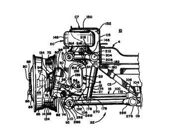
With particular reference to FIG. 4, the knuckle post 12 is formed from a
series of integrally formed webs or legs including an upper leg 24, a lower
leg 26, an
inner leg 28, and an outer leg 30 to define a generally A-shaped member with a
generally oblong brake through hole 32 defined by an inner surface 50. The
knuckle
CA 02313108 2000-06-06
WO 99/30956 -g- PCTNS98/26271
post 12 is preferably cast from steel, or alternatively can be forged. All
legs 24, 26,
28, 30 have substantially rectangular cross-sections. . The upper leg 24 has a
lobe 34
with an upper wishbone bearing aperture 36 and a keyhole 62 machined
perpendicular
to the axis of the aperture 36. The lower leg 26 also has a lobe 38 with a
lower
wishbone bearing aperture 40 and a keyhole 64 machined perpendicular to the
axis of
the aperture 40. Furthermore, the lower leg 26 includes a first scalloped
portion 42
adjacent to the lobe 38 at the intersection of an outer surface 44 and rear
surface 46 of
the lower leg 26. The lower leg 26 has a second scalloped portion 47 adjacent
to lobe
38 at the intersection of an outer surface 44 and a front surface 52. The
outer leg 30
has a third scalloped portion 48 adjacent to the lower leg 26 at the
intersection of an
inner surface 50 and rear surface 46 of the outer leg 30. The outer leg 30 has
a
kingpin boss 54 protruding from an outer surface 56. A cylindrical bore 58 is
machined through the boss 54 for accepting a kingpin 94 and a kingpin bushing
or
bearing (not shown) which are conventional and well known. A keyhole 60 is
machined perpendicular to the axis of the bore 58. The kingpin or steering
axis 59 is
inclined to exhibit camber as well as caster so that good steering stability
is provided
at large steering excursions. Camber is preferably selected at 6.5 degrees and
caster at
3.0 degrees. Although the knuckle post is preferably made with the reinforcing
leg
28, the knuckle post can be made into a C-shape without the leg 28. In this
case, the
upper leg 24 can be shaped to project inwardly in a triangular fashion to
support the
pedestal assembly 146.
The steering knuckle 14 is usually made using a well-known forging process
that results in the formation of a spindle 66 which extends outwardly and upon
which
the bearings 70 of a brake drum 68 are piloted. A wheel hub 86 is secured to
the
brake drum 68 by bolts 88 fastened at a flange 90. The steering knuckle 14
includes
an upper kingpin boss 72 and a lower kingpin boss 74 which are formed as one
piece
with the steering knuckle and extend outwardly from a central mounting plate
76
which is provided with a plurality of mounting apertures FIG. 2 for securing a
spider
assembly 300 of an S-cam brake assembly 18 (FIG. 6) in conventional fashion.
The
upper kingpin boss 72 includes an upper kingpin bore 80. In axial alignment
with the
upper kingpin bore 80 is a lower kingpin bore 82 formed in the lower kingpin
boss 74.
CA 02313108 2000-06-06
WO 99/30956 _g- PCTNS98/26271
A tie-rod arm attachment boss 84 is formed on an inner end of the lower
kingpin boss
74 and includes a tie-rod arm attachment bore 92.
The knuckle post 12 is pivotally connected to the steering knuckle 14 by
passing a kingpin 94 through the upper and lower kingpin bosses 72, 74 of the
steering knuckle 14 and through the kingpin boss 54 of the knuckle post 12.
The
bores 58, 80, and 82 are provided with kingpin bushings (not shown) and the
kingpin
94 is secured in the bosses by an upper screw-in cap 96 and a lower screw-in
cap 98.
The steering linkage assembly 16 is shown in FIGS. 1, 5 and 6 and includes a
tie rod 100, a tie-rod anm 102, and a steering arm 104. The tie rod 100 has a
first end
106 which is adjustable by means of toe-in adjustment mechanism 112 and is
pivotally connected to the steering arm 104 at a second end 108. The second
end 108
includes toe-in adjustment mechanism 114 and ball joint 110 with a stud
portion 116.
The tie-rod arm 102 has a tie-rod attachment boss 122 at a first end 120 and a
pin 124
at a second end 126. The tie rod 100 is pivotally connected to the tie-rod arm
102 by
journalling the stud portion 116 through a bore (not shown) in the tie rod
attachment
boss 122 and securing it thereto by a castle nut 130.
The steering linkage assembly 16 is connected to the steering knuckle 14 by
passing the pin 124 of the tie-rod arm 102 through the tie-rod arm attachment
bore 92
of the steering knuckle 14 and securing it by a castle nuts 132, a cotter pin
(not
shown), and a key (not shown). These connections are conventional in the
steering
suspension art.
The S-cam brake assembly 18 is also shown in FIGS. 3, 7, 8 and 10 and
includes a brake actuator 134 mounted to a bracket 136. The brake assembly 18
comprises a spider assembly 300 to which is mounted conventional brake shoes
302
that are moved by 'means of an S-cam 306 attached to a camshaft 308 housed in
a
support tube 140 and splined in conventional fashion to a slack adjuster 138.
Rotation
of the S-cam 306 biases the brake shoes 302 against the inside of the brake
drum 68 to
apply the brakes. The support tube 140 passes through an aperture 144 in the
bracket
136 and is non-rotatably attached to the spider assembly 300 and supports the
camshaft which passes therethrough. A push rod 142 extends from the brake
actuator
134 to and pivotally connects with the slack adjuster 138 by conventional
pivot
mounting. Activation of the brake actuator 134 rotates the slack adjuster and
the
CA 02313108 2000-06-06
WO 99/30956 _ 1 p_ PCT/US98/26Z71
camshaft to rotate the S-cam to apply the brakes. Rotation of the steering
knuckle 14
induces rotation of the brake assembly 18 since both are fixed to the spider
assembly.
Referring now to FIG. 3, the air spring assembly 20 includes an air spring 148
supported at one end by a pedestal assembly 146 mounted to the knuckle post 12
and
at the other end to a wheel case housing 152 through a stop plate 150. The
pedestal
assembly 146 includes a pair of parallel gussets 154. The lower surface 1 S 8
of the
gussets 154 are welded to an outer surface 160 of the upper leg 24 as
illustrated in
FIG. 2. The upper surfaces 164 of the gussets 154 are welded to a support
plate 168
so that an outer end 170 abuts the lobe 34. The support plate 168 is provided
with an
aperture 172 for securing the air spring 148 to the pedestal assembly 146. The
stiffness of the air spring can be controlled by changing the air pressure
within the air
spring bellows. However, since air suspension does not normally provide
dampening,
shock absorbers are also connected to the knuckle post 12 to further improve
the
stability of the suspension link structure.
The location of the air spring directly on top of the knuckle post is
advantageous to the invention. The air spring location provides for
substantially all of
the air springs' force to be used to respond to the road induced loads on the
spindle.
The air spring sits atop the knuckle post 12, which effectively permits almost
all of its
force to be applied to the spindle 66 because the kingpin connection is for
all practical
purposes a rigid connection. Prior suspensions mounted the air spring to one
of the
wishbones, A-arms, or similar components instead of the knuckle, which results
in a
portion of the air spring force being transferred to and absorbed by the
pivotal
connection of the wishbone or A-arm to the vehicle frame.
The shock absorber assembly 21 includes a shock absorber 174 with a lower
end 178 pivotally connected to a lower shock bracket 176 and an upper end 180
pivotally connected to an upper shock bracket 182. The upper shock bracket 182
is
mounted to the wheel case housing 152 and the lower shock bracket 176 is
welded to
the outer surface 44 of the lower leg 26. The lower shock bracket 176 extends
outwardly and upwardly from the outer surface resulting in the inclination of
the
longitudinal axis of the shock absorber 174. The oscillation resulting from
the jounce
or rebound of the knuckle post 12 is dampened by the shock absorber 174.
CA 02313108 2000-06-06
WO 99/30956 -I I _ PCTNS98/26271
With particular reference to FIGS. 5 and 6, the wishbone assembly 22 includes
an upper wishbone 184 and a lower wishbone 186. The uplrer wishbone 184
includes
a first control arm 188 and a second control arm 190. The first control arm
188
comprises an inboard link 192 and an outboard link 194 interconnected by a
central
link 196 through a first ball-and-socket joint 198 and second ball-and-socket
joint
200. The inboard link 192 has an inboard end 202 which is movably connected to
the
wheel case housing 152 through a pin 208 and bushing 204 disposed within bore
206.
The second control arm 190 comprises an inboard link 212 and an outboard link
214
interconnected by a central link 216 through a first ball-and-socket joint 218
and
second ball-and-socket joint 220. The inboard link 212 has an inboard end 222
which
is movably connected to the wheel case housing 152 through a pin and bushing
(not
shown) disposed within bore 228. The upper wishbone 184 extends laterally
outwardly relative to the vehicle body and is rotatably connected to the
knuckle post
12 by passing a swivel pin 236 through bores 238, 240 at outboard ends 230,
232 of
the first and second control arms, respectively, and through an antifriction
bearing 234
disposed within the upper wishbone aperture 36 of the knuckle post I2 and
secured by
a pin and nuts 242.
With particular reference to FIG. 6, the lower wishbone 186 includes a first
control arm 244 and a second control arm 246. The first control arm 244
comprises
an inboard link 248 and an outboard link 250 interconnected by a central link
252
through a first ball-and-socket joint 254 and second ball-and-socket joint
256. The
inboard link 248 has an inboard end 258 which is movably connected to the
wheel
case housing 152 through a pin 260 and bushing 262 disposed within bore 264.
The
second control arm 246 comprises an inboard link 266 and an outboard link 268
interconnected by a central link 270 through a first ball-and-socket joint 272
and
second ball-and-socket joint 274. The inboard link 266 has an inboard end 276
which
is movably connected to the wheel case housing 152 through a pin and bushing
(not
shown) disposed within bore 280. The lower wishbone 186 extends laterally
outwardly relative to the vehicle body and is rotatably connected to the
knuckle post
12 by passing a swivel pin 282 through bores 284, 286 at outboard ends 288,
290 of
the first and second control arms, respectively, and through an antifriction
bearing
CA 02313108 2000-06-06
W0 99/30956 _ 12- PCTNS98/262,~1
(not shown) disposed within the lower wishbone aperture 40 of the knuckle post
12
and secured by pin nuts 242.
In FIGS. 7 and 8, the structural elements of the forward-right suspension
elements are shown in an outer wheel cut position. Steering articulation is
conveyed
to the tie-rod attachment boss 84 by the steering linkage assembly 16 for
turning a
right steering knuckle 14. During a right-hand curve, a maximum steering angle
of
approximately 50 degrees is made possible by the suspension geometry. As a
right
turn is made, the brake through hole 32, the first scalloped portion 42 and
the third
scalloped portion 48 of the knuckle post 12 provide a space for the slack
adjuster 138,
bracket 136 and a portion of the support tube 140 to enter during rotation of
the wheel
to the position shown in FIGS. 7 and 8 without interference from the knuckle
post 12
or any portion thereof. At a maximum steering, the slack adjuster 138 and
bracket
136 are positioned slightly within the hole 32 and the support tube 140 is
positioned
adjacent to the third scalloped portion 48. The first scalloped portion 42
provides a
space for free passage of the tie-rod arm 102 and is positioned adjacent
thereto at a
maximum steering excursion. As a left turn is made, the second scalloped
portion 47
provides a space for free passage of a portion of the tie-rod attachment boss
84 and
castle nut 132.
The knuckle post design, including the opening 32, advantageously permits a
greater steering angle for a steering suspension incorporating an S-cam brake.
The
steering knuckle design has further benefits in that the front leg extends
substantially
directly between the pivot connections with the upper and lower wishbones,
providing
a more direct transfer of force from the wheel to the air spring. Although the
knuckle
of the invention is shown as having upper, lower, inboard and outboard legs,
it is
within the scope of the invention to have a single leg extending between the
upper and
lower wishbones. The open space inboard of the single leg will function as the
opening 32 for receiving the S-cam brake assembly at the maximum steering
angle.
Alternatively, the knuckle post could be made from just the upper, lower, and
inboard
legs, resulting in a curved open-faced knuckle. However, such a structure will
have
an increased cost because of the manufacturing methods and material needed to
ensure the curved knuckle could support the anticipated loads without failure.
CA 02313108 2000-06-06
WO g9~3p9~ _13_ PCT/US98/26271
FIG. 9 schematically illustrates the steering geometry of the invention. It
should be noted that the angles of the geometry are exaggerated for clarity. A
tire 310
mounted to the wheel 86 has a central axis or tire axis 312. The angle the
tire axis
forms relative to a true vertical axis 310 defines the camber angle , which is
preferably 6.5°.
The distance between the steering axis 59, defined by the kingpin 94, and the
vertical axis 310 at the tire/road interface defines the scrub radius Rs. The
scrub
radius is preferably as small as possible all things being equal because the
scrub
radius Rs forms the moment arm for any moment applied to the suspension
associated
with the road induced forces applied to the tire 310. Therefore, for a given
road
induced force, the greater the scrub radius, the greater will be the moment
applied to
the suspension. An increased scrub radius and its associated moment will
impact the
handling characteristics of the vehicle and the robustness of the steering
system
components and/or size of the air springs. Generally, a shorter scrub radius
provides
more desirable handling qualities. However, some scrub radius is desired for
handling stability. For the invention, the scrub radius is preferably 2-4
inches for a
steering axis angle of 5-7°.
The advantageous features of the knuckle post construction include a brake
through hole and scalloped portions result in an independent suspension system
wherein brake and steering assembly elements can rotate through a greater
angle of
rotation without interference with other structural elements. The resulting
increased
steering angle provides for increased vehicle maneuverability. Furthermore,
the
knuckle post construction provides for a suspension system with increased
rigidity
and therefore a vehicle with higher load carrying capacity.
Additionally, the air spring can be mounted directly onto the knuckle post
with
the knuckle post design of the invention, which minimizes the scrub radius and
thus
reduces the required size of the air spring. The result of which is that a
smaller air
spring can be used, reducing cost, or a greater vehicle load capacity can be
obtained,
increasing user function, or a combination of both. An alternative result is
that a
larger air spring can be used at a lower air pressure for the same equivalent
force
output. The suspension according to the invention also has a relatively small
scrub
radius for better handling.
CA 02313108 2000-06-06
WO 99/30956 _14_ PCT/US98/26271
The combined benefits of the knuckle post design, air spring location, and
short scrub radius, results in a superior independent front suspension, which
has a
greater steering angle, increased loading capacity, and improved handling
characteristics over previous suspensions.
Reasonable variation and modification are possible within the spirit of the
foregoing specification and drawings without departing from the scope of the
invention.