Language selection

Search

Patent 2313353 Summary

Third-party information liability

Some of the information on this Web page has been provided by external sources. The Government of Canada is not responsible for the accuracy, reliability or currency of the information supplied by external sources. Users wishing to rely upon this information should consult directly with the source of the information. Content provided by external sources is not subject to official languages, privacy and accessibility requirements.

Claims and Abstract availability

Any discrepancies in the text and image of the Claims and Abstract are due to differing posting times. Text of the Claims and Abstract are posted:

  • At the time the application is open to public inspection;
  • At the time of issue of the patent (grant).
(12) Patent: (11) CA 2313353
(54) English Title: BUSHING FOR OIL FILM BEARING
(54) French Title: BAGUE POUR PALIER A FILM D'HUILE
Status: Deemed expired
Bibliographic Data
(51) International Patent Classification (IPC):
  • B21B 31/07 (2006.01)
  • F16C 13/02 (2006.01)
(72) Inventors :
  • WOJTKOWSKI, THOMAS C., JR. (United States of America)
  • DOLAN, TIMOTHY S. (United States of America)
(73) Owners :
  • SIEMENS INDUSTRY, INC. (United States of America)
(71) Applicants :
  • MORGAN CONSTRUCTION COMPANY (United States of America)
(74) Agent: FETHERSTONHAUGH & CO.
(74) Associate agent:
(45) Issued: 2004-08-10
(22) Filed Date: 2000-07-04
(41) Open to Public Inspection: 2001-01-13
Examination requested: 2000-07-04
Availability of licence: N/A
(25) Language of filing: English

Patent Cooperation Treaty (PCT): No

(30) Application Priority Data:
Application No. Country/Territory Date
09/351,797 United States of America 1999-07-13

Abstracts

English Abstract

An oil film bearing for a roll neck in a rolling mill, comprising a bearing chock containing a bushing having a lining of babbitt metal. A sleeve is removably received on and rotationally fixed relative to the roll neck. The sleeve is journalled for rotation within and is axially shiftable with respect to the bushing. An abutment protrudes radially from an exposed outboard end of the sleeve for engagement by an outboard end face of the bushing during axial removal of the bearing from the roll neck. The lining of babbitt metal is recessed axially inwardly from the bushing outboard end face by a distance sufficient to prevent it from being damaged by engagement with the radially protruding abutment.


French Abstract

Un palier à film d'huile pour un tourillon dans un laminoir, comprenant une cale de palier contenant une bague ayant un revêtement de métal antifriction. Un manchon est reçu de façon amovible et est fixé de façon rotationnelle par rapport au tourillon. Le manchon est monté pour être en rotation à l'intérieur et peut être déplacé axialement par rapport à la bague. Une butée dépasse radialement d'une extrémité extérieure exposée du manchon pour un engagement par une face de l'extrémité extérieure de la bague au moment du retrait axial du palier du tourillon. Le revêtement de métal antifriction présente axialement et intérieurement un retrait par rapport à la face de l'extrémité extérieure de la bague d'une distance suffisante pour éviter qu'il soit endommagé par un engagement avec la butée qui dépasse radialement.

Claims

Note: Claims are shown in the official language in which they were submitted.


6


THE EMBODIMENTS OF THE INVENTION IN WHICH AN EXCLUSIVE
PROPERTY OR PRIVILEGE IS CLAIMED ARE DEFINED AS FOLLOWS


1. An oil film bearing for a roll neck in a rolling mill, said bearing
comprising:
a bearing chock;
a bushing contained by said bearing chock, said bushing having a lining of
babbitt metal;
a sleeve adapted to be removably received axially on and rotationally fixed
relative to the roll neck, said sleeve being journalled for rotation within
and being
axially shiftable with respect to said bushing, said sleeve having an end
section
protruding axially beyond an end face of said bushing; and
an abutment protruding radially from the end section of said sleeve for
engagement by a circumferential segment of the end face of said bushing during
axial
removal of said bearing from said roll neck, said circumferential segment
having a
distance, said lining of babbitt metal being recessed axially inwardly from
the end face
of said bushing by a distance sufficient to prevent said lining from being
damaged by
the engagement of the bushing end face with said abutment.

2. The oil film bearing of claim 1 wherein said lining of babbitt metal has a
thickness of between about 0.125 to 9.23 mm, and is recessed axially inwardly
from the
end face of said bushing by a distance greater than the minimum of said
thickness
range.

3. The oil film bearing of claim 1, wherein said lining of babbitt metal has
a thickness of between about 0.750 to 3.25mm, and is recessed inwardly from
the end
face of said bushing by a distance greater than the minimum of said thickness
range.

4. The oil film bearing of claim 1 wherein said distance is at least 10% of
said distance of said circumferential segment.


7


5. The oil film bearing of claim 1 wherein said distance is about 15% of
said distance of said circumferential segment.

Description

Note: Descriptions are shown in the official language in which they were submitted.


CA 02313353 2000-07-04
BUSHING FOR OIL FILM BEARING
FIELD OF THE INVENTION
This invention relates generally to oil film bearings of the type employed to
rotatably
support the necks of rolls in a rolling mill, and is concerned in particular
with an improvement in
the bushings employed in such bearings.
BACKGROUND OF THE INVENTION
In a conventional oil film bearing of the type shown in Figure 1, a sleeve 10
is axially
received on the tapered section 12 of a roll neck protruding axially from the
roll body 16. The
sleeve has a tapered interior surface 18 axially received on the tapered roll
neck section 12, and a
cylindrical outer surface 20 journalled for rotation in a bushing 22 contained
in and fixed relative
to a chock 24. The bushing has an internal lining 23 of babbitt metal. One end
of the sleeve is
provided with a radially outwardly protruding circular flange 26, as well as
with a radially
inwardly protruding circular collar 28. Keyways 30 are machined into the
collar 28. Keys 32 are
received in notches 34 in a reduced diameter cylindrical extension 36 of the
roll neck. The keys
32 protrude into the keyways 30 in the inner sleeve collar 28 to fix the
sleeve 10 against rotation
relative to the tapered roll neck section 12.
2 0 Other conventional bearing components include an inboard seal assembly 38,
sleeve
retaining ring 40, roller thrust bearing 42 and associated retaining and
outboard sealing elements
generally depicted at 44.
2

CA 02313353 2000-07-04
The chock 24, bushing 22, sleeve 10 and the other above described conventional
components are axially receivable on and removable from the roll neck as a
single unit or
assembly. During axial removal, the chock 24 is pulled in the direction of
arrow 46. The bushing
22 follows the chock, and by virtue of the interengagement of the outboard end
face 22a of the
bushing with the sleeve flange 26, the sleeve is axially dislodged from the
tapered section 12 of the
roll neck.
In a recent development directed to reducing the size of the forgoing from
which the sleeve
is machined, the sleeve flange 26 has been eliminated and replaced by an
improved keying
arrangement. An oil filin bearing incorporating one embodiment the redesigned
sleeve and keying
10 arrangement is shown in Figures 2 and 3, where like reference numerals have
been employed to
identify conventional components described earlier with reference to Figure 1.
The redesigned
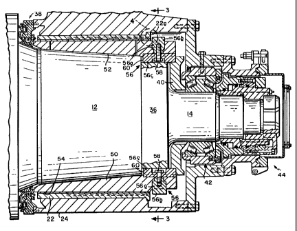
sleeve 50 is again provided with a tapered interior surface 52 seated on the
tapered section 12 of
the roll neck, and a cylindrical outer surface 54 journalled for rotation in
the bushing 22 contained
within the chock 24.
Key assemblies generally indicated at 56 are employed to rotatably fix the
sleeve 50 to the
roll neck. Each key has a generally T-shaped configuration, with a radial
segment 56a having a
protruding outer portion 56b defining an abutment engageable by the bushing
end face 22a during
axial removal of the bearing from the roll neck. The radial segment 56a
extends through a stepped
bore in the sleeve 50 and is connected to a base segment 56c by means of a
bolt 58 or other like
2 0 fastener. The base segment 56c is received in a groove 60 cut into the
cylindrical neck section 36
adjacent to the tapered section 12 of the roll neck. The radially protruding
outer portions 56b of
the keys 56 take the place of the conventional circular sleeve flange 26,
thereby making it possible
3

CA 02313353 2004-04-13
4
to reduce both the size of the forgoing from which the sleeve is machined, and
the costs
of machining the sleeve.
As can best be seen in Figure 3, the contact areas between the radially
protruding abutment portions 56b of the new keying arrangements 56 and the end
face
22a of the bushing are relatively small, indeed comprising only a fraction of
the entire
circumference of the end face 22a. Thus, during removal of the bearing from
the roll
neck, a concern has arisen that the resulting concentrated unit loading on the
bushing
end face may cause distress in the lining 23 of babbitt metal.
Thus it is desirable to try to safeguard the lining of babbitt metal from such
distress during removal of the bearing assembly from the roll neck.
SUMMARY OF THE INVENTION
According to one aspect of the invention, there is provided an oil film
bearing
for a roll neck in a rolling mill, said bearing comprising: a bearing chock; a
bushing
contained by said bearing chock, said bushing having a lining of babbitt
metal; a sleeve
adapted to be removably received axially on and rotationally fixed relative to
the roll
neck, said sleeve being journalled for rotation within and being axially
shiftable with
respect to said bushing, said sleeve having an end section protruding axially
beyond an
end face of said bushing; and an abutment protruding radially from the end
section of
said sleeve for engagement by a circumferential segment of the end face of
said
bushing during axial removal of said bearing from said roll neck, said lining
of babbitt
metal being recessed axially inwardly from the end face of said bushing by a
distance
sufficient to prevent said lining from being damaged by the engagement of the
bushing
end face with said abutment.

CA 02313353 2004-04-13
BRIEF DESCRIPTION OF THE DRAWINGS
Figure 1 is a longitudinal sectional view of a rolling mill oil film bearing
incorporating a conventional sleeve and keying arrangement;
5 Figure 2 is a longitudinal sectional view similar to Figure 1 illustrating a
recent
development incorporating a redesigned sleeve and keying arrangement;
Figure 3 is a sectional view taken along line 3-3 of Figure 2; and
Figure 4 is an enlarged view of the circled area of Figure 2.
DETAILED DESCRIPTION OF PREFERRED EMBODIMENT
With reference to Figure 4, it will be seen that the lining 23 of babbitt
metal has
been recessed axially inwardly from the bushing end face 22a by a distance
"X". The
distance "X" is sufficient to prevent the lining from being damaged or
distressed by
engagement of the bushing end face 22a with the abutment 56b, and is at least
10% and
preferably about 15% of the distance "Y" of the circumferential segment of the
end
face 22a contacted by the abutment portion 56b of each key assembly 56. The
lining of
babbitt metal 23 typically has a thickness of between about 0.125 to 9.53 mm,
preferably between about 0.750 to 3.25 mm, and the distance "X" is greater
than the
minimum lining thickness of the aforesaid ranges.
The lining recess may be achieved either by masking the area 22b to prevent
coverage during application of the babbitt metal, or by subsequently machining
babbitt
metal from area 22b.

Representative Drawing
A single figure which represents the drawing illustrating the invention.
Administrative Status

For a clearer understanding of the status of the application/patent presented on this page, the site Disclaimer , as well as the definitions for Patent , Administrative Status , Maintenance Fee  and Payment History  should be consulted.

Administrative Status

Title Date
Forecasted Issue Date 2004-08-10
(22) Filed 2000-07-04
Examination Requested 2000-07-04
(41) Open to Public Inspection 2001-01-13
(45) Issued 2004-08-10
Deemed Expired 2015-07-06

Abandonment History

There is no abandonment history.

Payment History

Fee Type Anniversary Year Due Date Amount Paid Paid Date
Request for Examination $400.00 2000-07-04
Registration of a document - section 124 $100.00 2000-07-04
Application Fee $300.00 2000-07-04
Maintenance Fee - Application - New Act 2 2002-07-04 $100.00 2002-06-14
Maintenance Fee - Application - New Act 3 2003-07-04 $100.00 2003-06-09
Maintenance Fee - Application - New Act 4 2004-07-05 $100.00 2004-04-05
Final Fee $300.00 2004-05-31
Maintenance Fee - Patent - New Act 5 2005-07-04 $200.00 2005-06-22
Maintenance Fee - Patent - New Act 6 2006-07-04 $200.00 2006-06-19
Maintenance Fee - Patent - New Act 7 2007-07-04 $200.00 2007-06-18
Maintenance Fee - Patent - New Act 8 2008-07-04 $200.00 2008-06-18
Maintenance Fee - Patent - New Act 9 2009-07-06 $200.00 2009-06-08
Maintenance Fee - Patent - New Act 10 2010-07-05 $250.00 2010-06-08
Registration of a document - section 124 $100.00 2010-07-13
Maintenance Fee - Patent - New Act 11 2011-07-04 $250.00 2011-06-14
Maintenance Fee - Patent - New Act 12 2012-07-04 $250.00 2012-06-06
Maintenance Fee - Patent - New Act 13 2013-07-04 $250.00 2013-06-07
Owners on Record

Note: Records showing the ownership history in alphabetical order.

Current Owners on Record
SIEMENS INDUSTRY, INC.
Past Owners on Record
DOLAN, TIMOTHY S.
MORGAN CONSTRUCTION COMPANY
WOJTKOWSKI, THOMAS C., JR.
Past Owners that do not appear in the "Owners on Record" listing will appear in other documentation within the application.
Documents

To view selected files, please enter reCAPTCHA code :


To view images, click a link in the Document Description column. To download the documents, select one or more checkboxes in the first column and then click the "Download Selected in PDF format (Zip Archive)" or the "Download Selected as Single PDF" button.

List of published and non-published patent-specific documents on the CPD .

If you have any difficulty accessing content, you can call the Client Service Centre at 1-866-997-1936 or send them an e-mail at CIPO Client Service Centre.


Document
Description 
Date
(yyyy-mm-dd) 
Number of pages   Size of Image (KB) 
Representative Drawing 2001-01-02 1 22
Cover Page 2001-01-02 1 49
Abstract 2000-07-04 1 19
Description 2000-07-04 4 141
Claims 2000-07-04 2 47
Drawings 2000-07-04 3 120
Description 2004-04-13 4 158
Claims 2004-04-13 2 44
Drawings 2004-04-13 3 118
Representative Drawing 2004-07-08 1 31
Cover Page 2004-07-08 1 58
Assignment 2000-07-04 6 299
Correspondence 2000-07-26 4 184
Prosecution-Amendment 2003-10-09 2 73
Prosecution-Amendment 2004-04-13 8 241
Correspondence 2004-05-31 1 30
Assignment 2010-07-13 11 330