Note: Descriptions are shown in the official language in which they were submitted.
CA 02313363 2000-07-04
r ,
ACOUSTIC WIND BAND
FIELD OF THE INVENTION
The present invention relates in general to a gas exhaust system, and
particularly, the present invention relates to an acoustical wind band for use
with an exhaust
device for exhausting gas from, for example, the interior of a building. The
invention is
especially useful in improving the entrainment of environmental air into the
exhaust fume
thereby improving the discharge velocity of the exhaust gas and therefore the
effective stack
height of the exhaust device and also in improving the sound attenuation of
noise from the
exhaust device or exhaust device outlet.
BACKGROUND OF THE INVENTION
Conventional exhaust systems are typically manufactured having a fan and a
nozzle device for pulling a gas out of the interior of a building and then
increasing the velocity
of the exiting air in order to properly dispel the air and also to avoid re-
entrainment of the
discharged air. In this regard, reference is made to U.S. Patent No.
4,806,076, issued to
Andrews, and U.S. Patent No. 5,439,349, issued to Kupferberg, which are
designed to provide
a high velocity jet for exhausting atmosphere and other gases. These exhaust
fans are
typically mounted on the roof areas of buildings and are used to carry exhaust
gases as high
as possible above the roof line of the building so as to ensure an effective
final dilution of the
gases within the greatest possible volume of ambient air and to ensure their
dispersal over a
large area with maximum dilution.
CA 02313363 2000-07-04
-2-
For example, the radial upblast exhaust fan apparatus described and shown in
U.S. Patent No. 4,806,076 has a nozzle in which two converging flow paths are
defined by
two respective passageways. A fan means is positioned within the fan housing
to urge
exhaust gases to flow upwardly through the exhaust paths. A passive zone
located between
the two flow paths supplies environmental air for mixing by induction into the
contaminated
gases being exhausted through the converging flow paths.
In addition, prior art devices for exhausting gases to atmosphere can have a
wind band, or annular ring, that may be positioned vertically extending in
general parallel
relationship with respect to an upper end of the fan or nozzle housing in
order to facilitate
mixing of the exhausted gas with ambient environmental air. For example, a
wind band can
be provided at one end of the two passages at the outlets of the radial
upblast exhaust fan
apparatus described and shown in U.S. Patent No. 4,806,076, to provide an
entrainment of
fresh air to mix with and dilute the gases exhausting from the two
passageways. Another
conventional wind band is shown and described in U. S. Patent No. 5,439,349,
which describes
a ring defining an annulus provided at the outlet end of a bifurcated stack to
induce ambient
air to mix with the spent air exhausting from the bifurcated tubular member.
Typically, the wind band is located in spaced relation with respect to an
outer
wall of the fan or nozzle housing by, for example, a wind band bracket means.
In this manner,
when gases are exhausted through the discharge of the exhausting device,
ambient
environmental air will be introduced between the space, formed between the
outer wall of the
exhausting device and the side wall of the wind band, and mix with and dilute
the exhausting
gases. However, conventional wind bands are limited in the amount of
entrainment that they
can achieve due to their design and construction.
In addition, conventional exhaust fans for moving large volumes of air often
generate high levels of noise which is undesirable. As a result, a wide
variety of fan silencing
equipment has been proposed to absorb fan noise, thereby reducing fan noise to
an acceptable
level. However, conventional silencers are typically used at the fan portion
of the device, and
thus do not control noise at the nozzle or outlet portion. These conventional
silencers are
undesirable for several reasons, including because they lead to an increase in
the overall height
of the fan device and they are limited to a relatively low air distribution
velocity (on the order
CA 02313363 2000-07-04
-3-
of less than about 3000 feet per minute) in which they are effective (e.g.,
provide maximum
attenuation without themselves generating any significant additional noise).
One conventional exhaust system that attempts to reduce fan noise at the
nozzle or outlet portion to an acceptable level is pending U.S. patent
application entitled
"Acoustic Silencer Nozzle", serial number 09/390,796, filed September 7, 1999,
which
describes a high velocity silencer nozzle for reducing the amount of noise
generated by the
exhausting gases as they exit through the exhausting device. The acoustic
silencer nozzle
provides acoustically absorbing media or resonating chambers adjacent the
converging
exhaust paths of the nozzle. In this manner, the noise at the nozzle or outlet
portion is reduced
and a tighter plume of high discharge flow is achieved. However, these
conventional silencers
are limited in their ability to block noise, such as line of sight noise, from
the exhausting gas
at the outlet portion or portions of the exhaust device.
Therefore, a need exists for a device that improves the entrainment of ambient
environmental air with the exhausting gases and also that improves sound
attenuation of the
discharging gases at the outlet portion of the fan, nozzle, stack, silencer,
ducting, or the like,
while still maintaining a relatively low height of the exhausting device and
providing a
relatively high air distribution velocity, without adding significantly to
system pressure.
SUMMARY OF THE INVENTION
The present invention is directed to an apparatus, system, and method for
improving the entrainment of ambient environmental air with the exhaust gas
passing through
the acoustical wind band and for improving the attenuation of sound from the
exhaust gas
exiting the exhaust device. The acoustic wind band apparatus can be used with
a gas exhaust
device having a discharge outlet portion for exhausting gas in a gas exhaust
system. The
acoustical wind band includes a plurality of spaced apart wind band sections,
each wind band
section having a top end defining a top opening, a bottom end defining a
bottom opening, and
one or more side walls disposed between and connecting the top end to the
bottom end. The
plurality of wind band sections are disposed circumferentially and in vertical
spaced relation
over the discharge outlet portion of the gas exhaust device and extending
generally upward
therefrom.
CA 02313363 2000-07-04
ti
-4-
The acoustic wind band apparatus includes a plurality of passages formed
around a peripheral of the acoustical wind band and disposed circumferentially
about the
discharge outlet portion. Each passage draws a flow of gas from environmental
atmosphere
outside the acoustical wind band to induce a flow of environmental gas from
therebelow to
mix with and dilute gas from the discharge outlet portion inside the
acoustical wind band. The
number of the plurality of passages corresponds to a number of the plurality
of wind band
sections. The acoustic wind band includes at least a first passage formed
between one of a top
wall and a side wall of the exhaust device and the side wall of the lower most
wind band
section and at least a second passage formed between a second wind band
section side wall
and the first wind band side wall.
Each sections can include one of a cylindrical shape, a straight conical
shape,
a curved conical shape, a square shape, and a rectangular shape. The bottom
opening and the
top opening can comprise one of a circular shape, a square shape, and a
rectangular shape.
Preferably, the side walls of adjacent sections of the plurality of wind band
sections are
parallel with respect to one another. Each wind band section has a smallest
diameter or width
greater than a diameter or width of the discharge outlet portion.
Preferably, the first, lowest most, wind band section is positioned over and
about the discharge portion and each vertically successive section is larger
than the preceding
section and each vertically successive section is positioned over and about
the preceding
section. Alternatively, the first, lowest most, wind band section can be
positioned over and
about the discharge portion and each vertically successive section can be
smaller than the
preceding section and each vertically successive section can be positioned
over and within the
preceding section.
The acoustic wind band apparatus includes support structures disposed between
and connection the acoustical wind band to the exhaust device. The support
structures also
hold the plurality of wind band sections in spaced apart relation with respect
to one another.
The acoustical wind band can be constructed to improve sound attenuation of
the exhaust gas exiting the exhaust device. For example, the bottom end of the
first, lowest
most, wind band section preferably extends at least to a horizontal plane
defined by a line of
sight of the discharge outlet portion and the bottom end each vertically
successive wind band
CA 02313363 2000-07-04
-5-
section preferably extends at least to a horizontal plane defined by the top
end of a vertically
preceding wind band section.
A further embodiment within the scope of the present invention is directed to
a system that improves the entrainment of ambient environmental air with the
exhausting
gases and also that improves sound attenuation of noise generated by the
exhaust device or
by the discharging gases at the outlet portion of the device. The system
includes an exhaust
device and an acoustical wind band. The exhaust device can include any
conventional exhaust
device, including for example, a fan, a nozzle, a stack, a silencer, ducting,
piping, or the like.
A gas movement device is provided as part of, or separately from the gas
exhaust device. A
drive mechanism, such as an electric motor, is provided to generate a flow of
exhaust gas
through the exhaust device. The drive mechanism can be directly coupled to the
gas
movement device, or may be indirectly coupled to the gas movement device
through, for
example mechanical linkage or belt and pulley arrangement.
In one embodiment of the present invention, the exhaust device can include a
radial upblast, mixed flow, centrifugal, or axial exhaust fan, including a
main housing having
a fan housing in the lower section thereof and acoustic silencer nozzle
positioned above the
fan housing and extending upwardly therefrom. The exhaust device can include
one or more
vertical flow paths and thus one or more upper contaminated air outlets.
In another embodiment of the present invention, the exhaust device can include
an exhaust fan apparatus, such as a centrifugal fan scrolling casing, with a
centrifugal fan
impeller mounted on an axle within the casing and having an axis of rotation
at right angels
to the side members of the scroll casing. In operation, the impeller, driven
by motor, draws
an exhaust gases from a building containing airborne contaminants through duct
and then
upwardly into the stack or nozzle by first passing through a diffuser and then
double
passageways.
The acoustical wind band apparatus is positioned circumferentially around and
in vertical spaced relation over the discharge outlet portion of the gas
exhaust device and
extending generally upward therefrom. The acoustical wind band includes a
plurality of
passages formed around a peripheral of the acoustical wind band and disposed
circumferentially about the discharge outlet portion. Each passage draws a
flow of gas from
environmental atmosphere outside the acoustical wind band to induce a flow of
environmental
CA 02313363 2000-07-04
-6-
gas from therebelow to mix with and dilute gas from the discharge outlet
portion inside the
acoustical wind band. A flow of fluid exiting one or more exhaust flow paths
and passing
through the acoustical wind band sets up aspiration in such a manner so that
the further flow
of fluid is drawn from ambient atmosphere through the passages.
The acoustical wind band can be constructed to improve sound attenuation by
blocking a direct line of sight of noise generated to the exhausting gas.
Preferably, a bottom
end of a first, lowest most, wind band section extends at least to a
horizontal plane defined by
a line of sight of the discharge outlet portion and the bottom end each
vertically successive
wind band section extends at least to a horizontal plane defined by a top end
of a vertically
preceding wind band section.
A further embodiment within the scope of the present invention is directed to
a method for improving the entrainment of ambient environmental air with the
exhausting
gases, while still maintaining a relatively low height of the exhausting
device, thus providing
a relatively high air distribution velocity, without adding significantly to
system pressure. The
method includes providing a gas exhaust device having a gas inlet opening for
receiving a gas
to be exhausted and a gas outlet opening for discharging the gas to
atmosphere, disposing an
acoustic wind band having a plurality of vertically spaced apart wind band
sections over and
about the exhaust gas outlet of the exhaust device, forming a plurality of
passages for drawing
ambient environmental air from a point outside the acoustical wind band to a
point inside the
acoustical wind band, wherein a number of the plurality of passages
corresponds to a number
of the plurality of wind band sections, and wherein a first passage is formed
between a
housing of the gas exhaust device and an inner surface of the lower wind band
section and
each successive passage is formed between an outer surface of a preceding wind
band section
and an inner surface of a successive wind band section, and inducing a
plurality of flows of
ambient environmental air through the plurality of passages to be mixed with
and dilute the
exhaust gas discharging from the exhaust device discharge.
According to another aspect of the invention, the method includes forming
each ofthe wind band sections extending upward and inward to form an angle
inclined toward
an upper, center region of the acoustical wind band. The angles act to
increase one or more
of a velocity and a volume of the exhaust gas flowing through the acoustical
wind band.
CA 02313363 2000-07-04
-7-
A further embodiment within the scope of the present invention is directed to
a method for improving sound attenuation in a gas exhaust system, such as a
fan, nozzle,
stack, silencer, ducting, piping, or the like. The method includes providing a
gas exhaust
device having a gas inlet opening for receiving a gas to be exhausted and a
gas outlet opening
for discharging the gas to atmosphere, disposing an acoustic wind band having
a plurality of
vertically spaced apart wind band sections over and about the exhaust gas
outlet of the exhaust
device, positioning a first, lower wind band section such that at least a
portion of a bottom end
of the lower wind band section blocks a direct line of sight from a point
outside the exhaust
device and the lower wind band section from a point inside the exhaust device
and the lower
wind band section, positioning each vertically successive wind band section
such that at least
a portion of a bottom end of a vertically successive wind band section blocks
a direct line of
sight from a point outside a vertically preceding wind band section and the
successive wind
band section from a point inside the preceding wind band section and the
successive wind
band section, and blocking noise generated by the exhaust device and the
exhaust gas outlet
opening from radiating along a direct line of sight from a point inside the
acoustical wind
band and the exhaust device to a point outside the acoustical wind band and
the exhaust
device.
According to another aspect of the invention, the method includes forming
each of the wind band sections extending upward and inward to form an angle
inclined toward
an upper, center region of the acoustical wind band. The angles act to reflect
noise inward and
upward through the acoustical wind band thereby improving sound attention.
BRIEF DESCRIPTION OF THE DRAWINGS
The foregoing and other aspects of the present invention will become apparent
from the following detailed description of the invention when considered in
conjunction with
the accompanying drawings. For the purpose of illustrating the invention,
there is shown in
the drawings embodiments that are presently preferred, it being understood,
however, that the
invention is not limited to the specific methods and instrumentalities
disclosed. In the
drawings:
Figure 1 is a plan view of an exemplary gas exhaust system having an acoustic
wind band in accordance with the present invention;
CA 02313363 2000-07-04
-8-
Figure 2 is an exploded view of the exemplary acoustic wind band of Figure
1;
Figure 3 is a cross sectional view of the gas exhaust system of Figure 1 taken
along line 3-3;
Figure 4 is a cross sectional view of the gas exhaust system of Figure 1;
Figure 5 is a plan view of another exemplary acoustic wind band in accordance
with the present invention;
Figure 6 is a plan view of another exemplary gas exhaust system having an
acoustic wind band in accordance with the present invention;
Figure 7A is a plan view of another exemplary gas exhaust system having an
acoustic wind band in accordance with the present invention;
Figure 7B is a side cross sectional view of the silencer nozzle of Figure 7A
taken along lines 7B-7B;
Figure 8 is a front plan view of an alternative embodiment of the acoustic
silencer nozzle of the present invention showing a remotely positioned
embodiment of a fan
drive;
Figure 9 shows an exemplary acoustical wind band disposed circumferentially
and in spaced relation about one or more discharge outlets of an exemplary
exhaust fan
apparatus;
Figure 10A is a front elevation of an exemplary acoustic silencer nozzle
incorporated into another exhaust fan in accordance with the present
invention;
Figure 10B is a vertical cross section taken along line l OB-1 OB of Figure
10A;
and
Figure 11 is a schematic view of the gas exhaust system of Figure 1
illustrating
exemplary exhaust gas and entrainment air flows through the acoustical wind
band in
accordance with the present invention.
DETAILED DESCRIPTION OF PREFERRED EMBODIMENTS
The present invention is directed to an apparatus, system, and method for
optimizing air entrainment and sound attenuation of gases being discharged
from one or more
outlet portions of a gas exhaust device using an acoustic wind band. The
acoustical wind band
CA 02313363 2000-07-04
-9-
of the present invention helps improve entrainment of ambient environmental
air with the
exhaust gases being discharged from the exhausting device resulting in a tight
plume of high
velocity flow which improves the effective stack height of the exhausting
device. The
acoustical wind band also helps to block line of sight noise from the outlet
of the exhausting
device thereby improving sound attenuation. In addition, the acoustical wind
band can help
to protect the vena contracta produced by the converging flow (plume) of
exhaust gas from
environmental conditions, such as for example, wind shear.
As shown in the Figures, the acoustical wind band 2 includes two or more
sections 3 disposed concentrically over and about the discharge of the
exhausting device 4 and
in spaced relation to the outlet portion 5 of the exhaust device 4 and in
spaced relation with
any adjacent sections 3. The sections 3 may have a cylindrical shape, a square
shape, a
rectangle shape, or preferably, the sections have a conical shape. Each
section 3 has a smallest
width or diameter greater than the width or diameter of the discharge opening
5 of the
exhausting device 4 to allow proper discharge of the exhaust gas from the
device. The
sections 3 are positioned in vertical, spaced succession, preferably with each
successive
section being larger (having a greater cross-sectional width or diameter) than
the preceding
section and being disposed over and about the preceding section.
Alternatively, each
successive section can be smaller (having a lesser cross-sectional width or
diameter) than the
preceding section and being disposed over and within the preceding section.
A passageway is formed between each vertically successive sections to provide
a pathway for the entrainment of ambient environmental air from outside the
acoustical wind
band with the exhaust gas being discharged inside the acoustical wind band by
the exhausting
device. Preferably, at least a portion of the top end and the bottom end of
adjacent sections
are coplanar, or preferably overlap, one another to block noise generated by
the exhaust device
or exhaust gas at the discharge from directly exiting the wind band.
Figure 1 shows an exemplary acoustical wind band 2 in accordance with the
present invention mounted to an exemplary exhausting device 4. As shown in
Figure 1, the
acoustical wind band 2 can include two conical-shaped sections 3 (hereinafter
also referred
to as a lower cone 3a and an upper cone 3b) positioned concentrically about a
discharge
opening 5 of an exhausting device 4. The inner cone 3a is positioned over and
about the
discharge outlet portion or portions 5 of the exhausting device 4. The outer
cone 3b,
CA 02313363 2000-07-04
-10-
preferably being larger than the preceding inner cone 3a, is positioned over
and about the
inner cone 3a. The sections 3 may be positioned extending generally vertically
in general
parallel relationship with respect to'an upper discharge end 5 of the
exhausting device 4.
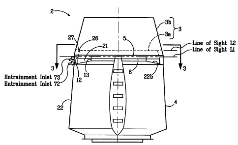
Figure 2 shows an exploded view of the exemplary acoustical wind band 2 of
Figure 1, having a lower, inner conical section 3a and an upper, outer conical
section 3b. As
shown in Figure 2, the lower section 3a includes a top end 6 defining a top
opening 7, a
bottom end 8 defining a bottom opening 9, and at least one side wall 10
disposed between and
connecting the top end 6 to the bottom end 8. Each lower section 3a side wall
10 includes an
inner surface 11 and an outer surface 12. As shown, the top opening 7 and the
bottom opening
9 of the lower section have a circular shape.
As shown in Figures 1, 3, 4, 5, 6, 7, and 9, the acoustic wind band apparatus
2 includes a first passage 21 formed between the lower section 3a and a
housing 22 of the gas
exhaust device 4. Preferably, the first passage 21 is defined by the inner
surface 11 of the
lower section 3a and one or more of a side wall 22a, as shown in Figures 7 and
9, and a top
wall 22b, as shown in Figures 1 and 6, of the gas exhaust device housing 22.
The movement
of the primary exhaust stream of fluid, as represented by arrow 70 in Figures
4 and 11, sets
up aspiration in such a manner so that one or more secondary streams of fluid,
as represented
by arrows 72 of Figures 1, 4, and 11, are drawn from the ambient fluid of the
atmosphere. In
this manner, the first passage 21 draws a first flow of gas 72 from
environmental atmosphere
to induce a flow of environmental gas from therebelow, to mix with and dilute
exhaust gas
exiting from the discharge outlet portions 5 of the exhaust device 4.
As shown, the acoustical wind band 2 includes at least a second passage 26
formed between the lower section 3a and the upper section 3b. Preferably, the
second passage
26 is defined by the inner surface 19 of the upper section 3b and the outer
surface 12 of the
lower section 3a. The movement of the primary exhaust stream of fluid 70 sets
up aspiration
in such a manner so that one or more secondary streams of fluid, as
represented by arrow 73
of Figures 1, 4, and 11, are drawn from the ambient fluid of the atmosphere.
In this manner,
the second passage 26 draws a second flow of gas 73 from environmental
atmosphere to
induce a further flow of environmental gas from therebelow to further mix with
and dilute gas
from the one or more discharge outlets 5 of the exhaust device 4.
CA 02313363 2000-07-04
-11-
In an alternate embodiment (not shown) having three sections, a third passage
would be formed between the second and the third sections, in another
alternate embodiment
(not shown) having four sections, a fourth passage would be formed between the
third and the
fourth sections, etc. Each addition section helps form an additional passage
for the
entrainment of ambient environmental air from therebelow with the main stream
of
exhausting gas. The number of sections is dependent on the particular
application and the
desired system operating characteristics, including entrainment properties,
actual and effective
stack height, discharge velocity, dilution and distribution of the exhaust
gas, etc.
As shown in Figures 1, 3, 4, and 5, the lower section 3a is disposed
circumferentially and in spaced relation about one or more discharge outlet
portions 5 of a gas
exhaust device 4 and extends generally upward therefrom. As shown in Figure 1,
the bottom
end 8 of the lower section 3a preferably extends at least to a plane defined
by the one or more
discharge outlets 5 of the exhausting device 4 (e.g., they are coplanar), and
more preferably,
overlap one another (e.g., the bottom end 8 of the lower section 3a extends
below a horizontal
plane defined by an uppermost point of the discharge 5 of the exhaust device
4). For example,
the bottom end 8 of the lower section 3a is positioned relative to an upper
most portion of a
discharge outlet 5 of the exhausting device 4 such that the direct line of
sight L 1 from a point
outside the exhausting device 4 and acoustical wind band 2, does not reach a
point along the
direct line of sight inside the exhausting device 4 and acoustical wind band
2. Consequently,
a barrier is provided so that no free path is available by which sound waves
(e.g., noise)
originating within the exhausting device 4 or at the discharge outlet 5 can
travel directly to
points outside the exhausting device 4. Accordingly, the only surfaces visible
from outside
the exhausting device 4 and acoustical wind band 2 are an outer surface 13 of
the exhausting
device 4 and/or the outer surface 12 of the lower section 3a. This feature
provides sound
attenuation of line of sight noise.
Also, Figure 2 shows an exemplary upper section 3b having a top end 14
defining a top opening 15, a bottom end 16 defining a bottom opening 17, and
at least one side
wall 18 disposed between and connecting the top end 14 to the bottom end 16.
The upper
section 3b side wall 18 includes an inner surface 19 and an outer surface 20.
As shown, the
vertically successive upper section 3b is larger than the preceding lower
section 3a. As
CA 02313363 2000-07-04
-12-
shown, the top opening 15 and the bottom opening 17 of the upper section 3b
have a circular
shape.
As shown in Figure 1, the upper section 3b is disposed circumferentially and
in spaced relation about the lower section 3a and extends generally upward
therefrom. The
bottom end 16 of the upper section 3b preferably extends at least to a plane
defined by the top
end 6 of the lower section 3a (e.g., they are at least coplanar), and more
preferably, they
overlap one another (e.g., the bottom end 16 of the upper section 3b extends
below a
horizontal plane defined by the top end 6 of the lower section 3a). For
example, as shown in
Figure 1, the bottom end 16 of the upper section 3b is positioned relative to
an upper most
portion of the top end 6 of the lower section 3a such that the direct line of
sight L2 from a
point outside the acoustical wind band 2, does not reach a point along the
direct line of sight
inside the acoustical wind band 2. Consequently, a barrier is provided so that
no free path is
available by which sound waves (e.g., noise) originating within the exhausting
device 4 or at
the discharge outlet 5 can travel directly to points outside the acoustical
wind band 2.
Accordingly, the only surfaces visible from outside the exhausting device 4
and acoustical
wind band 2 are the outer surfaces 20 of the upper section 3b and/or the outer
surface 12 of
the lower section 3a. This feature provides sound attenuation of line of sight
noise.
In alternative embodiments (not shown), the acoustical wind band may have
three sections, four sections, five sections, etc. Preferably, each vertically
successive section
is constructed and positioned relative to the preceding section as described
above with respect
to an acoustical wind band having two sections.
Alternatively, as shown in Figure 5, the lower section 3c can have a width or
diameter larger than the width or diameter of the vertically successive, or
upper section 3d.
Again, each section 3 has a smallest width or diameter greater than the width
or diameter of
the discharge opening 5 of the exhausting device 4 to allow proper discharge
of the exhaust
gas from the device. As shown in Figure 5, the sections 3 can be positioned in
vertical, spaced
succession, preferably with each successive section 3d being smaller (having a
smaller cross-
sectional width or diameter) than the preceding section 3c and being disposed
over and within
the preceding section 3c.
As shown in Figure 5, at least a portion of the top end and the bottom end of
adjacent sections can be coplanar, or preferably overlap, one another to block
noise generated
CA 02313363 2000-07-04
-13-
by the exhaust device or exhaust gas at the discharge from directly exiting
the wind band.
Passages are formed between the housing of the exhaust device and between each
vertically
successive sections to provide a pathway for the entrainment of ambient
environmental air
from outside the acoustical wind band with the exhaust gas being discharged
inside the
acoustical wind band by the exhausting device.
The side wall 10 of the lower section 3a and the side wall 18 of the upper
section 3b may extend upward substantially vertically, thus forming a
cylindrical section,
upward and inward having a curved surface thereby forming bell-shaped
sections, or
preferably, the side walls 10,18 extend upward and inward substantially in a
straight line
toward the center of the acoustical wind band 2 thereby forming conical shaped
sections, as
shown in the Figures.
As shown in Figure 6, the conical shaped sections 3a,3b can include a first
angle 0 formed by one of a top wall 22b and a side wall 22a of the gas exhaust
device 4 from
the horizontal. The first angle 0 helps to maximize or improve air entrainment
and sound
attenuation properties of the exhausting gas. For example, as shown in Figures
1 and 6, the
first angle 0 can be formed between a top wall 22b of the exhaust device
housing 22 and
horizontal. As shown in the embodiment of Figures 1 and 6, the first angle 0
can be about 10
degrees to about 30 degrees. In other exemplary embodiments shown in Figures 9
and 10A,
the first angle 0 can be formed by the side wall 22a of the exhaust device
housing 22 and the
horizontal. As shown in the embodiment of Figure 9, the first angle 0 can be
about 70 degrees
to about 85 degrees.
Preferably, the one or more side wall 10 of the lower section 3a extend
generally upward and inward from the bottom end 8 to the top end 6 to form a
second angle
a from the horizontal. The second angle a is formed between a horizontal plane
defined by
the bottom end 8 of the lower section 3a and the lower section side wall 10.
Preferably, the side wall 18 of the upper section 3b extends generally upward
and inward from the bottom end 16 to the top end 14 to form a third angle R
from the
horizontal. The third angle R is formed between a horizontal plane defined by
the bottom end
16 of the upper section 3b and the upper section side wall 18.
Preferably, the second angle a and the third angle 0 are formed depending on
the particular application in order to maximize air entrainment and sound
attenuation
CA 02313363 2000-07-04
-14-
properties of the acoustical wind band 2. For example, the second angle and
the third angle
are preferably formed as acoustically reflecting angled sections to reflect
noise inward and
upward to improve sound attenuation, and the angles also help to increase a
velocity of the
ambient environmental air entering the acoustical wind band. More preferably,
the second
angle a and the third angle 0 are formed at an angle between about 60 degrees
and about 90
degrees from the horizontal from inside of the wind band 2.
The upper section 3b and the lower section 3a may have a second and a third
angle that are different from one another (e.g., they are not parallel), or
preferably, the second
and a third angles a, R are the same (e.g., the lower section side wall 10 and
the upper section
side wall 18 are parallel). The angles are preferably predetermined based on
the particular
application in order to maximize entrainment by accelerating ambient
environmental air with
increasing velocity due to the angles.
Again, in an alternate embodiment (not shown) having three sections, a fourth
angle would be formed by the third section, in another alternate embodiment
(not shown)
having four sections, a fifth angle would be formed by the fourth section,
etc. Each addition
section results in an additional angle for increasing the velocity of the
ambient environmental
air for entrainment with the exhausting gas. The number of sections and the
angle of each
section is dependent on the particular application and the desired operating
characteristics,
including, for example, entrainment properties, actual and effective stack
height, discharge
velocity, dilution and distribution of the exhaust gas, etc.
The acoustical wind band is designed and constructed so as not to interfere or
disrupt the flow of the exhaust gas. For example, the height and angle of the
side walls of the
acoustical wind band are preferably constructed so as not to interfere or
disrupt the flow of
exhaust gases exiting the exhaust device and flowing through the acoustical
wind band. Each
wind band section preferably has a smallest diameter or width greater than a
diameter or width
of the discharge outlet portion of the exhaust device (e.g., as shown in the
Figures, the top end
of the upper most section does not interfere with the exhaust gas flow).
In addition, the overall height of the acoustical wind band is preferably kept
to a minimum while still achieving desired operating properties. For example,
the vertical
height of the lower section side wall 10 and the upper section side wall 18
can be designed and
constructed to keep the actual stack height of the exhaust device 4 and
acoustical wind band
CA 02313363 2000-07-04
-15-
2 to a minimum height while still providing adequate entrainment and
velocities of the
exhaust gas discharge plume to provide adequate dilution and distribution of
the exhaust gas
and to avoid re-entrainment of the exhaust gases. Preferably, each vertically
successive
section 3b has a height greater than the preceding section 3a.
The acoustical wind band includes support structures 27 for connecting the
acoustical wind band 2 to the exhaust device 4 and for holding the individual
wind band
sections 3 of the acoustical wind band 2 in spaced apart relation with respect
to the exhaust
device 4 and with respect to one another. The support structure 27 can include
any
conventional supporting techniques, including brackets, bolts, spacers, arms,
or the like, for
holding the acoustical wind band 2 in position over the exhaust device 4 and
about the outlet
portion 5 of the exhaust device 4, and for holding adjacent sections 3a,3b in
vertical spaced
relation.
As shown in Figures 1, 3 and 6, one suitable mounting structure includes a
plurality of wind band brackets 27. Preferably, at least three wind band
brackets 27, and more
preferably six wind band brackets 27 are used and are spaced at equal
distances around the
peripheral of the acoustical wind band 2, as shown in Figure 6. The wind band
brackets 27
are used to support the acoustical wind band 2 in spaced relation on the
exhaust device 4 and
to hold the wind band sections 3a,3b in spaced relation with respect to
adjacent sections.
Alternatively, separate support structures (not shown) can be provided, one to
connect the
acoustical wind band to the exhaust device and another to connect the wind
band sections
together.
The acoustical wind band 2 can be manufactured in one or more pieces and
may be cut, molded and formed into shape. For example, the acoustical wind
band can be
made from metallic sheets, such as steel or aluminum, that are cut into
sections and formed
into shape and can be coupled together using conventional fasteners or welding
techniques.
In addition, the acoustical wind band can be manufactured by cast or injection
molding. The
acoustical wind band can be made from any conventional material that is suited
for use on,
for example a rooftop, and that can withstand normal environmental conditions,
such as hot,
cold, dry, wet, and windy weather, and that can also withstand typical
discharge velocities and
exhaust gases that may be discharged through the wind band by the exhaust
device. For
example, the wind band material can be metallic, fiberglass, polypropylene, or
the like.
CA 02313363 2000-07-04
-16-
In addition, the inner surfaces 11,19 and the outer surfaces 12,20 of one or
more of the sections 3a,3b can include a sound reflecting and/or sound
absorbing material, as
shown in Figure 6. All or a portion of the inner surface and/or the outer
surface of one or
more of the sections may include a perforated material, such as perforated
steel, fiberglass,
or polypropylene. For example, as shown in Figure 6, the inner surfaces 11,19
of each of the
sections 3a,3b can include a sound reflecting and/or sound absorbing material.
As shown, a
first and second inner sheaths 28,29 may be disposed adjacent all or a portion
of the inner
surfaces 11,19 ofthe side walls 10,18 of the lower and upper sections 3a,3b,
respectively. The
inner sheaths 28,29 can include perforated pieces and can have respective
partitions spaced
therebetween, thus providing respective inner enclosed spaces or chambers
30,31. The inner
enclosed spaces can have disposed therein an acoustic absorbing material
32,33, such as
plastic, coated or galvanized steel, stainless steel, mineral wool, or a
fiberglass material, or
any acoustically treated media. The sections may also include a chemical
resistant wrap or
barrier (not shown) such as mylar, polyurethane, or similar material to
prevent exhaust
pollutants, moisture, or mold from accumulating in the acoustical material or
cavity.
Alternatively, the inner enclosed spaces 30,31 can each be a resonating
chamber. The inner
enclosed spaces or chambers 30,31 are closed at either end. As the exhaust gas
travels out of
the exhaust device 4 and through the acoustical wind band 2, noise can be
absorbed through
the perforations in the surfaces of the outer walls into the acoustical fill
material 32,33.
As shown in Figure 4, the exhaust device 4 can include any conventional gas
exhaust device using conventional gas exhausting techniques, including an air
moving device,
a fan, a discharge nozzle, a stack, a silencer, a duct work discharge, a pipe,
or the like. The
gas exhaust device 4 can have a gas moving mechanism 34 to move a gas from an
inlet 35 of
the gas exhausting device 4 to a discharge 5 of the gas exhausting device 4.
The gas moving
mechanism 34 can include, for example, a fan, a nozzle, a pump, a vacuum, or
the like, and
is provided with a drive mechanism 36, such as for example a motor, that may
be directly
coupled to the fan or may be belt driven from either the inside of the exhaust
device housing,
as shown in Figures 4 and 7B, or from outside of the exhaust device housing,
as shown in
Figures 8 and 10A.
Referring to Figures 7A and 7B, shown is a first exemplary embodiment in
accordance with the present invention including an acoustical wind band 2
having two or more
CA 02313363 2007-11-13
-17-
wind band sections 3 disposed circumferentially and in spaced relation, as
described in detail
herein above, over and about one or more discharge outlets of an acoustic
silencer nozzle
having a radial upblast, mixed flow, centrifugal or axial exhaust fan, such as
that described
and shown in pending U.S. patent application entitled "Acoustic Silencer
Nozzle", serial
number 09/390,796, filed September 7, 1999,
This pending patent application describes a high velocity silencer nozzle for
reducing the amount of noise generated by the exhausting gases as they exit
through the
exhausting device. As shown in Figure 7A and 7B, the acoustic silencer nozzle
4a provides
acoustically absorbing media or resonating chambers 39 adjacent the converging
exhaust
paths 53,55 of the nozzle 43.
As shown in Figures 7A and 7B, the exhaust fan apparatus, such as a radial
upblast, mixed flow, centrifugal, or axial exhaust fan, includes a main
housing 41 having a
fan housing 42 in the lower section thereof and acoustic silencer nozzle 43
positioned above
the fan housing 42 and extending upwardly therefrom. The fan housing 42
defines a fan inlet
44 adapted to receive gases for exhausting thereabove and a fan outlet 45 for
allowing
movement of the gases upwardly from the fan housing 42 into the acoustic
silencer nozzle 43.
The acoustic silencer nozzle 43 defines a first outer wall section 46 and a
second outer wall section 47 being generally conical sections and being
concave, cylindrical,
or straight with respect to one another. The acoustic silencer nozzle 43
further defines a first
upper air outlet 48 and a second upper air outlet 49 at the uppermost portion
thereof. A
passive zone section defining a passive zone chamber 50 can be located between
the first outer
wall section 46 and the first upper air outlet 48 and the second outer wall
section 47 and the
second upper air outlet 49. The passive zone supplies air for mixing by
induction into the
contaminated air being exhausted through the two upper outlets.
The passive zone section 50 defines a first inner wall section 52 which can be
shaped as a conical, cylindrical, or straight section being convex or straight
facing outwardly
toward the first outer wall section 46. A first exhaust flow path 53 is
defined between the first
inner wall section 52 and the first outer wall section 46. Ina similar manner,
the passive zone
section 50 defines a second inner wall section 54 which can be shaped as a
conical,
cylindrical, or straight section and is convex facing outwardly and in spaced
relation with
CA 02313363 2000-07-04
-18-
respect to the second outer wall section 47 to define a second exhaust flow
path 55 therebetween.
A first end wall 56, which may take the form of two end walls, may be
positioned extending between the first inner wall section 52 and the first
outer wall section
46. These end walls aid in the definition of the first exhaust flow path 53.
In a similar
manner, a second end wall 57, which may take the form of two second end walls,
can be
positioned extending from the second inner wall section 54 to the second outer
wall section
47 to facilitate defining the second exhaust flow path 55.
First and second outer sheaths 58,59 can be disposed adjacent the section of
the outer walls 46,47 and can comprise a perforated material. Similarly, inner
sheaths 60,61
can be disposed adjacent a perforated sections on the inner walls 52,54,
respectively. As the
air travels down the exhaust flow paths 53,55, noise can be absorbed through
the perforations
in the surfaces of the outer walls 46,47 and the surfaces of the inner walls
52,54 into an
acoustical fill material.
To facilitate the flow of air to be exhausted through the first and second
exhaust flow paths, a fan 62 may preferably be positioned within the fan
housing 42. The fan
can be operatively connected with respect to a fan drive 63 to control
operation thereof. The
fan drive 63 may be positioned within the passive zone chamber 50, may be
positioned
externally from the main housing 41 of the exhaust device as shown in Figure
8, or entirely
below the nozzle section. In the configuration shown in Figure 8, a belt drive
64 may be
included positioned within the passive zone section 50 and may be operatively
secured with
respect to the drive 63 which itself may be secured with respect to the outer
portion of the
main housing 41.
As shown, the exhaust device can include one or more vertical flow paths and
thus one or more upper contaminated air outlets (e.g., the exhaust gas outlet
or outlet
portions). Figures 7A and 7B show one on one side and one on another with a
passive zone
therebetween. Each of these can be divided into multiple sections such that
any number of
individual upper flow paths can be defined positioned circumferentially about
the passive
zone.
During operation of the exhaust device, a primary stream of fluid (e.g.,
exhaust
gas) can move at a velocity of, for example, at least about 2000 ft/min (with
respect to the
ambient fluid in the atmosphere), and preferably up to about 6600 ft/min. The
movement of
CA 02313363 2007-11-13
-19-
the primary stream of fluid sets up aspiration in such a manner so that two or
more secondary
streams or flows of fluid are drawn from the ambient fluid (e.g., air) of the
atmosphere.
It should be noted that the exhaust paths 53,55 preferably converge in order
to
keep the exhaust plume tight, which can create a current of air on the order
of, for example,
about 110 feet in diameter moving at about 250 ft/min in still air. This helps
to dilute effluent
or fumes prior to release into the atmosphere, thus effectively minimizing
pollution problems
with extremely high efficiency.
Another exemplary embodiment in accordance with the present invention is
shown in Figure 9. As shown in Figure 9, the acoustical wind band 2 can be
disposed
circumferentially and in spaced relation about one or more discharge outlets 5
of an exhaust
fan apparatus 4b, such as a radial upblast, mixed flow, centrifugal or axial
exhaust fan, such
as the exhaust fan apparatus described and shown in U.S. Patent No. 4,806,076
issued
February 21, 1989 to Andrews,
U.S. Patent No. 4,806,076 describes an exhaust nozzle in which two converging
flow paths
are defined by two respective passageways 23,24. The exhaust fan apparatus 4b
includes a
main housing 65 having a fan housing 66 and a nozzle 67. A fan means (not
shown) can be
positioned within the fan housing to urge exhaust gases to flow upwardly
through one or more
exhaust paths (not shown) formed in the nozzle 67. A passive zone 68 located
between the
two flow paths can supply environmental air for mixing by induction into the
contaminated
gases being exhausted through the converging flow paths.
Another exemplary embodiment in accordance with the present invention is
shown in Figures 1 OA and I OB. As shown in Figures 1 OA and I OB, the
acoustical wind band
2 can be disposed circumferentially and in spaced relation about one or more
discharge outlets
of an exhaust fan apparatus 4c, such as a centrifugal fan scrolling casing,
with a centrifugal
fan impeller mounted on an axle within the casing and having an axis of
rotation at right
angels to the side members of the scroll casing as described and shown in U.S.
Patent No.
5,439,349, issued August 8, 1995 to Kupferberg,
U.S. Patent No. 5,439,349 describes an apparatus 4c having a base 112 meant
to be mounted on a roof, a centrifugal fan casing 114 mounted on the base 112,
and an inlet
duct 116 extending to one side of the casing 114 from the interior of a
building (not shown).
CA 02313363 2000-07-04
-20-
Mounted to the top of the centrifugal fan casing 114 is an exhaust stack or
nozzle 118, and
topping the exhaust stack is an acoustical wind ban 2 having a frusto-conical
shape.
The base 112 includes a frame 122 on which a motor 124 is mounted. A shaft
126 is journaled in bearing brackets 128 mounted on the frame 122 and extends
within the
casing 132 in a cantilevered manner. The shaft 126 is driven by a drive belt
130 taken off the
motor 124. As shown in Figure 10A, shaft 126 mounts a centrifugal impeller 138
having
multiple vanes rotating about the axis of the shaft 126.
The casing 114 includes a scroll 132 surrounding the impeller 138 and
interrupted by discharge port 144. The scroll 132 includes a cut-off 134 near
the discharge
port 144. The casing 114 also includes parallel side walls 136. An inlet port
140 is defined
on one side wall 136 of the casing 114, and connector flanges 142 are provided
to fasten the
inlet port 140 with the inlet duct 116.
Thus, the spent gases containing airborne contaminants exhausting from the
building through the duct 116 enter the casing 114 axially relative to the
impeller 138, and the
air flow is accelerated through the discharge port 144. A diffuser tube 146 is
mounted to and
communicates with the discharge port 144. The diffuser tube 146 is in turn
connected to the
bifurcated duct 148 by means of connecting flanges 149. The bifurcated duct
148 includes
passageways 150 and 152 which are generally parallel although they, in fact,
converge slightly
toward the outlet. A central opening 155 is formed by means of inner flat
walls 154 and 156
defining the passageways 150 and 152 respectively.
In operation, the impeller 138, driven by motor 124, will draw the exhaust
gases from the building containing airborne contaminants through the duct 116
and then
upwardly into the stack or nozzle 118 by first passing through the diffuser
and then the double
passageways 150 and 152. The location of the casing 114 and, in particular,
the orientation
of the scroll 132 relative to the stack or nozzle 118, permits even
distribution of the air flow
into the diffuser and through the passageways 150 and 152. The spent gases
exhaust through
the outlet ports 158 and 160 at relatively high velocity and cause ambient air
to be induced
into the annulus or passages 21,26 of the acoustical wind band apparatus 2 to
mix with the
airborne contaminants and, therefore, dilute the exhaust.
The gas exhaust system 1 is preferably constructed to accommodate various
types of gases. For purposes of clarity, gas or exhaust gas, as used herein,
is intended to
CA 02313363 2000-07-04
-21-
encompass any medium which may be emitted through an exhaust device outlet,
including but
not limited to one or more gases, air, smoke, dust, fumes, air bourne
particles, fluid vapors,
or the like.
In addition, it is contemplated by the present invention that a spacer,
piping,
duct work, or the like can be positioned between the discharge of the exhaust
device and the
acoustical wind band. The acoustical wind band can be used on an exhaust
device having a
diverging, a straight, and a converging discharge flow of exhaust gas.
Exemplary Air Flows During Operation
Figure 11 is a schematic view showing exemplary flows for the exhaust gas
and entrainment of the ambient environmental air. As shown in Figure 11, a
primary exhaust
gas flow70 flows upward from, for example a fan discharge, and into one or
more gas paths
formed in, for example, a silencer nozzle. The nozzle increases the velocity
of the exhaust gas
as it exits one or more outlet portions of the nozzle and enters the
acoustical wind band
apparatus position above and about the discharge of the exhaust device.
The nozzle may include a passive zone chamber for the introduction of a flow
of primary ambient environmental air with the discharging exhaust gas at the
discharge of the
exhaust device. The passive zone supplies air as shown by arrow 71 for mixing
by induction
into the contaminated air being exhausted through the two upper outlets. Air
will also be
induced to flow from the passive zone chamber upwardly as shown by arrow 71
into the
contaminated gases being exhausted through the two upper outlets to facilitate
mixing
therewith. Preferably, the primary ambient air mixes with the exhausting air
immediately
upon movement of the exhausting gases outwardly through the upper outlet
portions of the
exhaust device discharge.
The acoustical wind band 2 acts to improve the air entrainment properties of
the exhaust device by providing two or more secondary flows of ambient
environmental air
through the two or more passages formed by the acoustical wind band. In this
manner, when
gases are exhausted through the discharge of the exhaust device, two or more
flows of
secondary ambient environmental air will be induced by the acoustical wind
band to flow as
shown in Figure 11 by arrows 72 and 73. Preferably, the secondary ambient air
mixes with
the exhausting air within the acoustical wind band upon movement of the
exhausting gases
CA 02313363 2000-07-04
-22-
upwardly through the acoustical wind band from the exhaust device discharge.
The flow of
the primary flow of ambient environmental air 71 and the secondary flows of
ambient
environmental air 72,73 mix with the exhaust gas flow 70 and form a high
velocity discharge
of diluted exhaust gas as indicated by arrow 74 exiting the top of the
acoustical wind band.
The wind band 2 also protects the vena contracta produced by the converging
flow (plume)
from the primary exhaust passageway.
Although illustrated and described herein with reference to certain specific
embodiments, it will be understood by those skilled in the art that the
invention is not limited
to the embodiments specifically disclosed herein. Those skilled in the art
also will appreciate
that many other variations of the specific embodiments described herein are
intended to be
within the scope of the invention as defined by the following claims.