Note: Descriptions are shown in the official language in which they were submitted.
CA 02313414 2000-07-05
SPECIFICATION
TITLE OF THE INVENTION
VEHICULAR TRANSMISSION CONTROL SYSTEM
FIELD OF THE INVENTION
The present invention relates generally to a vehicular
transmission which comprises a transmission capable of varying its speed
change ratio and of transmitting the driving force output from the engine to
the
drive wheels of a vehicle.
BACKGROUND OF THE INVENTION
Such vehicular transmissions have been used for mechanical
power transmission in vehicles. As speed change mechanisms incorporated in
these transmissions, not only gear transmissions with a plurality of speed
ratios
but also continuously variable transmissions with a belt, etc. have been used
for
speed change control. Recently, a hybrid transmission which uses an electrical
motor in addition to an engine has been introduced for fuel efficiency. The
applicant of the present invention is also developing a hybrid transmission.
This hybrid transmission comprises a continuously variable transmission with a
metal V-belt which is disposed around the common output shaft of an engine
and an electrical motor arranged in series, and the output shaft of the
continuously variable transmission is provided with a forward/reverse
switching
mechanism and a starting clutch (main clutch).
One purpose for developing this transmission is to improve fuel
efficiency. Therefore, there is a consideration that the operation of the
engine
- 1-
CA 02313414 2000-07-05
be controlled such that it stops when the vehicle has stopped ( referred to as
"idling elimination"). As such idling elimination control, there is a method
to
stop the engine when the engine comes into idling after the vehicle has
stopped
completely. However, when the vehicle is decelerated by releasing the
accelerator pedal that has been depressed, an engine brake is effected. It is
known that, during this deceleration, the fuel injection to the engine is
terminated (or the supply of fuel is terminated). In this situation, there is
a
more desirable way to eliminate engine idling. When the vehicle is decelerated
to a halt, the fuel injection is terminated, so this condition should be
maintained
to stop the engine. This method seems more favorable for improving the fuel
efficiency.
When the engine is stopped to avoid engine idling, the
transmission is set at a LOW ratio, and the supply of electricity to the
electromagnetic valves ( solenoid valves ) which control the speed change
operation may be stopped ( or the electrical currents supplied are reduced
almost to zero) because there is no need to perform any speed change.
While the engine is not operated, preferably, the supply of electricity to
such
electromagnetic valves be terminated, and the charge in the battery be
conserved for the time being. In this way, the charge in the battery can be
used more advantageously to power the electrical motor in an effective way.
Generally, the electromagnetic valves are disposed between a hydraulic pump
which is driven by the engine and hydraulically operated actuators which
systematically set the speed change ratio of the transmission. The spool of
each of these valves is disposed in a fine balance of biasing forces which are
generated by a resilient member such as spring, by the electromagnetism
created by a current through the solenoid of the valve and by a back pressure
-2-
CA 02313414 2000-07-05
fed back from the control pressure that controls the actuation of an actuator,
and they are systematically controlled to change the control pressures which
effect the speed change operation of the transmission.
If the operation of the engine is being terminated to avoid idling,
and when the rotational speed of the engine decreases below the idling
rotational speed of the engine, the output of the hydraulic pump, which is
driven by the engine, attenuates. As the pressure of the hydraulic circuit of
the transmission decreases, the back pressure acting on each electromagnetic
valve also decreases. In this situation, once the pressure of the hydraulic
circuit has begun decreasing, even though the electrical current necessary for
maintaining the speed change ratio of the transmission at a LOW ratio is
provided continuously, the spool of each electromagnetic valve starts to shift
in
the direction of the force generated the resilient member because the
decreasing back pressure creates a change in the above described balance. As
the spool comes close to the wall of the housing of the respective valve, it
happens to cause a chattering, which is a displeasing vibration and a noise.
SUMMARY OF THE INVENTION
It is an object of the present invention to provide a control
system for a vehicular transmission which system is capable of preventing
electromagnetic valves from chattering when the pressure of the hydraulic
circuit of the transmission decreases as the operation of the engine is
terminated to avoid engine idling.
In order to achieve this objective, the present invention provides
a first embodiment of control system for a mechanical power transmission
which is used for driving a vehicle. This control system comprises an engine,
-3-
CA 02313414 2000-07-05
a speed change mechanism (for example, the continuously variable
transmission CVT of the embodiment described in the following section), a
hydraulic pump and an electromagnetic valve (for example, the drive-pulley
electromagnetic valve 45 and the driven-pulley electromagnetic valve 46 of the
following embodiment). The speed change mechanism transmits the driving
force of the engine with speed change, and the hydraulic pump is driven by the
engine to deliver hydraulic oil. The electromagnetic valve is disposed between
a first oil passage (for example, the oil passage 103a and the oil passage
103b
of the following embodiment) and a second oil passage (for example, the oil
passage 107 and the oil passage 108 of the following embodiment ). In this
arrangement, the first oil passage leads to the pump while the second oil
passage leads to a speed change actuator ( for example, the variable width
drive
pulley 11 and the variable width driven pulley 16 of the following embodiment)
of the speed change mechanism. The electromagnetic valve adjusts the
pressure of the oil to control the speed change actuator in a balance of
first,
second and third biasing forces and delivers this control pressure into the
second oil passage. Here, the first biasing force is generated by a resilient
member, the second biasing force is generated electromagnetically, and the
third biasing force is generated by the back pressure from the second oil
passage. In this arrangement, the system according to the present invention
controls the vehicular transmission in the following way. After the rotational
speed of the engine has become below a reference rotational speed which is
lower than an idling rotational speed and after the pressure of the first oil
passage begins to decrease, for a predetermined time, the current to the
electromagnetic valve is adjusted and supplied to generate the second biasing
force in a magnitude that can supplement a decrease in the third biasing
force,
- 4-
CA 02313414 2000-07-05
which decrease is caused from a decrease in the pressure of the first oil
passage. Then, after the predetermined time has elapsed, the current supplied
to the electromagnetic valve is set almost to zero. The above mentioned
predetermined time corresponds, for example, to a time which takes, after the
pressure of the first oil passage begins to decrease, for the spool of the
electromagnetic valve to be pushed and shifted toward the wall of the housing
of the valve by the resilient member as the third biasing force decreases, so
as
to result in a chattering with the wall.
In this first embodiment of control system according to the
present invention, if the rotational speed of the engine decreases below the
reference rotational speed, which is lower than the idling rotational speed of
the
engine, for example, in an engine idling elimination control, and when the
pressure of the first oil passage begins to decrease, for the predetermined
time,
the current to the electromagnetic valve is adjusted and supplied to generate
the second biasing force in a magnitude that can supplement the third biasing
force which decreases in correspondence with the decreasing pressure of the
first oil passage. Therefore, it is not possible for the spool of the
electromagnetic valve to shift in correspondence to the decrease in the
pressure of the first oil passage, so no chattering of the spool with the wall
of
the housing will occur. Thus, the control system according to the present
invention effectively prevents the electromagnetic valve from causing any
displeasing vibration and noise. In addition, after the elapse of the
predetermined time, the current to the electromagnetic valve is set almost to
zero. By terminating the cause of chattering in this way, a further prevention
is made against vibrations and noises. As described above, even though the
engine rotational speed becomes below the reference rotational speed, the
- 5-
CA 02313414 2000-07-05
electromagnetic valve is supplied with a current which is sufficient to
maintain
the speed change ratio of the transmission at a LOW ratio until the pressure
of
the first oil passage begins to decrease. In this way, even in a case where
the
transmission comprises a belt type continuously variable transmission, a
predetermined pressure is secured for controlling pulleys which are
incorporated in the transmission, thereby preventing the belt from slipping.
A second embodiment of control system according to the present
invention comprises an engine, a speed change mechanism, a hydraulic pump
and an electromagnetic valve. The speed change mechanism transmits the
driving force of the engine with speed change, and the hydraulic pump is
driven
by the engine to deliver hydraulic oil. The electromagnetic valve is disposed
between a first oil passage and a second oil passage, and the first oil
passage
leads to the pump while the second oil passage leads to a speed change
actuator
of the speed change mechanism. The electromagnetic valve adjusts the
pressure of the oil to control the speed change actuator, in a balance of
first,
second and third biasing forces, and delivers this control pressure into the
second oil passage. Here, the first biasing force is generated by a resilient
member, the second biasing force is generated electromagnetically, and the
third biasing force is generated by the back pressure from the second oil
passage. In this arrangement, the system according to the present invention
controls the vehicular transmission in the following way. After the rotational
speed of the engine has become below a reference rotational speed which is
lower than an idling rotational speed and after the pressure of the first oil
passage begins to decrease, the current supplied to the electromagnetic valve
is
set almost to zero.
In this second embodiment of control system according to the
- 6-
CA 02313414 2000-07-05
present invention, if the rotational speed of the engine decreases below the
reference rotational speed, which is lower than the idling rotational speed of
the
engine, for example, in an engine idling elimination control, and when the
pressure of the first oil passage begins to decrease, the current to the
electromagnetic valve is adjusted almost to zero. By terminating the cause of
chattering in this way, a prevention is made against vibrations and noises. As
in the above described first control system, also in this control system, even
though the engine rotational speed becomes below the reference rotational
speed, the electromagnetic valve is supplied with a current sufficient to
maintain the speed change ratio of the transmission at a LOW ratio until the
pressure of the first oil passage begins to decrease. In this way, even if the
transmission comprises a belt type continuously variable transmission, a
predetermined pressure is secured for controlling pulleys which are
incorporated in the transmission, thereby preventing the belt from slipping.
Further scope of applicability of the present invention will
become apparent from the detailed description given hereinafter. However, it
should be understood that the detailed description and specific examples,
while
indicating preferred embodiments of the invention, are given by way of
illustration only, since various changes and modifications within the spirit
and
scope of the invention will become apparent to those skilled in the art from
this
detailed description.
BRIEF DESCRIPTION OF THE DRAWINGS
The present invention will become more fully understood from
the detailed description given herein below and the accompanying drawings
which are given by way of illustration only and thus are not limitative of the
-7-
CA 02313414 2000-07-05
present invention.
FIG. 1 is a cross-sectional view of a vehicular transmission which
incorporates a control system according to the present invention.
FIG. 2 is a schematic diagram showing the construction of the
power transmission mechanism of this transmission.
FIG. 3 is a flowchart showing some steps of an idling elimination
control according to the present invention, which control is effective when
the
transmission is operated to decelerate.
FIG. 4 is another flowchart showing further steps of the idling
elimination control.
FIG. 5 is another flowchart showing still further steps of the
idling elimination control.
FIG. 6 is another flowchart showing yet further steps of the
idling elimination control.
FIG. 7 is a flowchart showing steps of a control which terminates
the supply of the electrical current to the transmission.
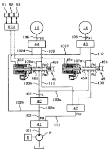
FIG. 8 is a diagram showing a hydraulic circuit which controls the
speed change operation of the transmission.
FIG. 9 carries graphs which show the chronological changes of
the following respective values which changes occur after the execution of the
idling elimination control: (A) the rotational speed Ne of the engine, ( B)
the pressure PL inside the oil passage connecting between an electromagnetic
valve provided for the driven pulley of the transmission and a hydraulic pump,
( C) the control current Idn supplied to control the pressure of the driven
pulley and (D) the pressure Pp2 which controls the driven pulley.
- 8-
CA 02313414 2000-07-05
DESCRIPTION OF THE PREFERRED EMBODIMENTS
FIG. 1 is a cross-sectional view of a vehicular transmission which
incorporates a control system according to the present invention. FIG. 2
shows the construction of the power transmission mechanism of this vehicular
transmission, which comprises an engine E, an electrical motor M, and a
continuously variable transmission CVT. The electrical motor M is disposed
over the output shaft Es of the engine while the continuously variable
transmission CVT is connected through a coupling mechanism CP to the engine
output shaft Es. The engine E is a fuel injection engine, so the injection of
fuel into the engine is terminated when the vehicle decelerates as described
in
detail later in this section. The electrical motor M is powered by a battery
which is mounted on the vehicle, and the electrical motor assists the driving
force of the engine. In this way, the vehicular transmission is constructed as
a
hybrid transmission with these two power sources.
The continuously variable transmission CVT comprises a metal
V-belt mechanism 10, a forward/reverse switching mechanism 20 and a starting
clutch (or main clutch) 5. The metal V-belt mechanism 10 is disposed
around the input shaft 1 and the countershaft 2 of the transmission, the
forward/reverse switching mechanism 20 is disposed over the input shaft 1, and
the starting clutch 5 is disposed on the countershaft 2. This continuously
variable transmission CVT is mounted on a vehicle, and the input shaft 1 is
connected through a coupling mechanism CP with the output shaft Es of the
engine. The driving force output from the transmission is transmitted through
the starting clutch 5 to the differential mechanism 8 and then used for
driving
axle shafts 8a and 8b to rotate the right and left wheels of the vehicle ( not
shown ) .
- g-
CA 02313414 2000-07-05
The metal V-belt mechanism 10 comprises a variable width drive
pulley 11, which is disposed over the input shaft 1, a variable width driven
pulley 16, which is disposed on the countershaft 2, and a metal V-belt 15,
which
is disposed around these pulleys 11 and 16. The drive pulley 11 comprises a
stationary pulley half 12, which is disposed rotatably on the input shaft 1,
and a
movable pulley half 13, which is movable with respect to the stationary pulley
half 12 in the axial direction of the pulley 11. On the outside of the movable
pulley half 13, a drive-pulley cylinder chamber 14 is defined by a cylinder
wall
12a which is fixed to the stationary pulley half 12. The pressure supplied
through a control valve CV and through an oil passage 31 into the cylinder
chamber 14 ( this pressure is referred to as "drive pulley pressure" )
generates
a thrust which shifts the movable pulley half 13 in the axial direction of the
drive pulley.
The driven pulley 16 comprises a stationary pulley half 17, which
is fixed on the countershaft 2, and a movable pulley half 18, which is movable
with respect to the stationary pulley half 17 in the axial direction of the
pulley.
On the outside of the movable pulley half 18, a driven-pulley cylinder chamber
19 is defined by a cylinder wall 17a which is fixed to the stationary pulley
half
17. The pressure supplied through the control valve CV and through an oil
passage 32 into the cylinder chamber 19 ( this pressure is referred to as
"driven pulley pressure" ) generates a thrust which shifts the movable pulley
half 18 in the axial direction of the driven pulley.
In this construction, the control system controls the hydraulic
pressures which are supplied into these cylinder chambers 14 and 19,
respectively, ( the side thrusts of the drive and driven pulleys ) by the
control
valve CV to generate appropriate lateral thrusts in these two pulleys.
- 10-
CA 02313414 2000-07-05
Specifically, the system, while preventing any slip of the belt 15, adjusts
the
difference between the pressures supplied to the drive and driven pulleys, so
that the side thrusts generated in the respective pulleys change the widths of
the V grooves of the drive and driven pulleys 11 and 16. Thereby, the pitch
radii of the respective pulleys for the V belt 15 are changed to vary the
speed
change ratio of the transmission continuously.
Furthermore, the forward/reverse switching mechanism 20 is a
planetary gear train, which comprises a sun gear 21, a ring gear 22, a carrier
23
and a forward clutch 25. The sun gear 21 is connected to the input shaft 1,
and the ring gear 22 is connected to the stationary pulley half 12 of the
drive
pulley 11. The carrier 23 can be held against rotation by a reverse brake 27,
and the forward clutch 25 can be operated to connect the sun gear 21 with the
ring gear 22. In this mechanism 20, when this forward clutch 25 is engaged,
all the gears 21, 22 and 23 rotate together with the input shaft 1 as a one
body,
and the drive pulley 11 is driven by the driving force of the engine E in the
same direction as the input shaft 1( i.e., in the forward direction of the
vehicle). On the other hand, when the reverse brake 27 is engaged, the
carrier 23 is held stationary, so the ring gear 22 rotates in the direction
opposite to that of the sun gear 21, and the drive pulley 11 is driven by the
driving force of the engine E in the direction opposite to that of the input
shaft
1 (i.e., in the reverse direction ).
The starting clutch 5 is a clutch to control the power
transmission between the countershaft 2 and the output members of the
transmission, i.e., gears 6a, 6b, 7a and 7b. When the starting clutch 5 is
engaged, the power is transmitted therebetween. In the condition where the
starting clutch 5 is engaged, the output of the engine, after undergoing the
- 11-
CA 02313414 2000-07-05
speed change by the metal V-belt mechanism 10, is transmitted through the
gears 6a, 6b, 7a and 7b to the differential mechanism 8 and then divided and
transmitted by the differential mechanism 8 to the right and left wheels. When
the starting clutch 5 is released, this power transmission is terminated, and
the
transmission comes into a neutral condition. The engagement of the starting
clutch 5 is carried out by a pressure supplied through the control valve CV
and
through an oil passage 33 ( this pressure is referred to as "clutch control
pressure").
In the continuously variable transmission CVT, the drive and
driven pulley pressures supplied through the control valve CV and through the
oil passages 31 and 32, respectively, are used for the speed change control
while the clutch control pressure supplied through the control valve CV and
through the oil passage 33 is used for the actuation of the starting clutch.
The
control valve CV itself is controlled by means of control signals sent from an
electrical control unit ECU.
In the vehicle incorporating this transmission, the electrical
motor M assists the engine E such that the engine E can operate in a range
which is most fuel efficient. To improve the fuel efficiency of the vehicle,
the
operation of the electrical motor M is controlled by means of control signals
which are sent from the electrical control unit ECU through a line 37. At the
same time, the speed change control is performed to achieve an optimal speed
change ratio for operating the engine E in a most fuel efficient manner. This
control is also carried out by means of control signals sent from the
electrical
control unit ECU through a line 35 to the control valve CV.
To further improve the fuel efficiency of the transmission, the
control system additionally performs an idling elimination control. Basically,
- 12 -
CA 02313414 2000-07-05
this idling elimination control is to stop the operation of the engine E when
the
vehicle stops, and when the driving force of the engine E becomes unnecessary,
i.e, the engine enters into an idling condition. However, to achieve a higher
level of fuel efficiency, this system goes further than this basic control.
Specifically, the system terminates the fuel supply to the engine and,
maintaining this condition, performs the idling elimination control. In
addition,
it controls to terminate the supply of the electricity to the electromagnetic
valves which are provided for speed change control in the continuously
variable
transmission CVT. In this way, the system minimizes the discharge of
electricity while the engine is not operated for idling elimination.
Now, these idling elimination control and current supply
termination control, which are executed on condition that the fuel injection
is
terminated to decelerate the vehicle, are described in reference to the
flowcharts shown in FIGS. 3 - 7 and to the hydraulic circuit diagram shown in
FIG. 8.
This control begins at Step Sl shown in FIG. 3, where a
judgment is made to find out whether a precondition for the idling elimination
control is satisfied or not. As preconditions, for example, the temperature of
the oil in the transmission must be above a predetermined value so as not to
cause any retardation in responsive actions, and the slope regression
inhibitor
of the transmission is in good condition. If such preconditions are not
satisfied,
then the control routine proceeds to Step S10 to control the engine in an
ordinary way. In other words, if the preconditions for the termination of the
fuel injection are not satisfied, then the control resumes the fuel injection
control. The above mentioned slope regression inhibitor functions to retain an
enough hydraulic pressure for the brake to keep the vehicle stationary on a
- 13 -
CA 02313414 2000-07-05
slope even while the driver is not depressing the brake pedal.
If the judgment at Step S1 is that the preconditions are satisfied,
then the control routine proceeds to Step S2, where a determination is made
whether the brake of the vehicle is on or off, i.e., the brake pedal is
depressed
or not. If the brake is off, then the control routine proceeds to Step S10 to
perform the ordinary drive control. On the other hand, if the brake is on,
then
the control proceeds to Step S3, where a determination is made whether the
transmission is in the reverse drive range or not. The idling elimination
control is executed only while the transmission is in the forward drive range.
Therefore, if the determination indicates that the transmission is in the
reverse
drive range, then the control routine proceeds to Step S10 to perform the
ordinary drive control. On the other hand, if the transmission is not in the
reverse drive range, then the control routine proceeds to Step S4, where a
determination is made whether the speed V of the vehicle is equal to or lower
than a predetermined speed Vs (e.g., 15 km/h ) or not. The idling
elimination control is a control which is executed when the vehicle is being
stopped. Therefore, if the vehicle is not driving at a low speed, the control
routine proceeds to Step S10 to perform the ordinary drive control.
When the speed of the vehicle decreases below the
predetermined speed, the control routine proceeds to Step S5, where a
determination is made whether the reduction ratio RR of the transmission is
equal to or greater than a predetermined reduction ratio R1 ( LOW ratio) or
not. The idling elimination control is executed to stop the engine, so if the
engine is stopped, then the speed change ratio cannot be changed thereafter.
Therefore, it is necessary that the speed change ratio be adjusted to a LOW
ratio before the start of the idling elimination control, so that the vehicle
can be
- 14-
CA 02313414 2000-07-05
started smoothly after the restart of the engine. Thus, the predetermined
reduction ratio Ri is a ratio (=2.2 ) near the LOW ratio ( =2.4), and the
determination at Step S5 is to determine whether the reduction ratio of the
transmission has become a ratio near the LOW ratio or not. Until such a ratio
is achieved, the control routine proceeds to Step S10 to perform the ordinary
drive control. When such a ratio is achieved, the control routine proceeds to
Step S6, where a determination is made whether the throttle of the engine is
closed completely or not. If the throttle is open, i.e., the accelerator pedal
is
depressed by the driver, then the control routine proceeds to Step S10 to
perform the ordinary drive control, and the idling elimination control is not
executed because the driver is judged having no intention to stop the vehicle.
As described above, only if the preconditions are satisfied, the
brake is on, the transmission is not in the reverse drive range, the vehicle
is
driving at a speed lower than the predetermined speed, the reduction ratio is
almost at the LOW ratio, and the throttle is closed completely, then the
idling
elimination control is executed. However, before the idling elimination
control,
further determinations are made at Step S7 whether preparations for the idling
elimination control are complete or not. Here, for example, if the air
conditioner of the vehicle is on or not, if there is enough charge in the
battery
or not, and if the negative pressure used to assist the operation of the brake
is
at an appropriate level or not are determined. If the air conditioner is on,
if
the battery do not have enough charge, or if the negative pressure for
assisting
the brake is short, then the control routine proceeds to Step S10 to perform
the
ordinary drive control. On the other hand, if these preparations are judged
complete, then the control routine proceeds to Step S11, where the control
transits to the idling elimination control.
- 15 -
CA 02313414 2000-07-05
The idling elimination control comprises a starting clutch
disengaging control S20 shown in FIGS. 4 and 5( the circled "A" of the
flowchart in FIG. 4 connects with that of FIG. 5, making up a continuous
flowchart) and an engine stop control S50 shown in FIG. 6.
At first, a description is given of the starting clutch disengaging
control S20. In this control, firstly, a starting clutch off mode selection
flag is
set up, F( SCMD )=1, at Step S21 to indicate that the control flow has arrived
at Step Sil. This flag is used as a judgment flag in the engine stop control
shown in FIG. 6. Next, at Step S22, a determination is made whether the
torque capacity of the starting clutch 5 has become zero, T ( SC ) =0, or not.
If
it is not zero, T ( SC ) ;40, then the control routine proceeds to Step S23,
where
a clutch gradual release flag is set up F( MCJ3 )=1. Then, at Step S24, a
target clutch pressure PC ( CMBS) is set for the starting clutch 5. This
target clutch pressure PC ( CMBS ) is a pressure to control the clutch so that
the torque capacity of the starting clutch becomes zero, T( SC )=0. On the
other hand, if the torque capacity is zero, T ( SC )=0, then the control
routine
proceeds to Step S25, where the clutch gradual release flag is set down, F
(MCJ3)=0.
Then, the control routine proceeds to Step S26, where a
determination is made whether or not this is the first flow through the
starting
clutch disengaging control. If it is the first flow, then a disengagement
control
flag is set up, F ( MCJ2 ) = 1, at Step S27. It is clear from this that the
disengagement control flag is set up, F ( MCJ2 )=1, when the starting clutch
disengaging control has just started.
Then, the control routine proceeds to Step S28, where a
determination is made whether the disengagement control flag is up, F ( MCJ2 )
- 16-
CA 02313414 2000-07-05
=1, or not. If the disengagement control flag is up, F( MCJ2 )=1, then the
control routine proceeds to Step S29, where a determination is made whether
the clutch gradual release flag is up, F ( MCJ3 )=1, or not. If the clutch
gradual release flag is up, F ( MCJ3 )=1, then a small value a(1) is set as a
pressure reduction value a to reduce the clutch control pressure gradually
because the starting clutch 5 needs to be released gradually. On the other
hand, if the clutch gradual release flag is down, F ( MCJ3 )=0, then a large
value a (2) (> a( 1) ) is set as the pressure reduction value a to
reduce the clutch control pressure rapidly because the starting clutch 5 can
be
released quickly as the torque capacity of the clutch is zero.
At Step S32, this pressure reduction value a is subtracted from
the starting clutch control pressure PC ( CMMC ) at the moment, and the
value resulted from this subtraction is compared with the target value, i.e.,
the
target clutch pressure PC ( CMBS ) set at Step S24. If the target value is
smaller than the value calculated in the above subtraction, i.e., the starting
clutch control pressure has not decreased to the target value, then the
control
routine proceeds to Step S33, where the value resulted from the subtraction of
the pressure reduction value a from the current starting clutch control
pressure PC ( CMMC ) is set as a new starting clutch control pressure to
control the starting clutch.
On the other hand, if the target value is equal to or greater than
the value calculated in the above subtraction, i.e., the starting clutch
control
pressure has decreased to the target value, then the control routine proceeds
to
Steps S34, S35 and S36. There, the disengagement control flag is set down, F
( MCJ2 )=0, at Step S34, the clutch gradual release flag is set down, F ( MCJ3
)
=0, at Step S35, and the target clutch pressure PC ( CMBS ) is set as the
- 17-
CA 02313414 2000-07-05
starting clutch control pressure PC ( CMMC ) at Step S36. It is clear from the
above description that, in the starting clutch disengaging control S20, the
clutch
control pressure is decreased gradually to the target clutch pressure PC
( CMBS ), i.e., the starting clutch 5 is released gradually.
Now, a description is given of the engine stop control S50 shown
in FIG. 6. In this control, at first, a determination is made whether the
starting clutch off mode selection flag is up, F ( SCMD )=1, or not at Step
S51.
If it is down, F ( SCMD )=0, which condition indicates that the above
mentioned starting clutch disengaging control S20 is not being performed, then
the control routine proceeds to Step S54, where an idling elimination control
flag is set down, F( ISOFF )=0. In this case, the idling elimination control
is
not performed. On the other hand, if the starting clutch off mode selection
flag
is up, F ( SCMD )=1, which condition indicates that the above mentioned
starting clutch disengaging control S20 has been started, then the control
system judges that the conditions required for stopping the engine are
satisfied
and allows the engine to be stopped by maintaining the stoppage of the fuel
injection. Therefore, the control routine proceeds to Step S52, where a
determination is made whether or not the disengagement control flag is down,
F( MCJ2 ) =0, i.e., whether the control for releasing the starting clutch 5
gradually so as to make the torque capacity of the starting clutch 5 zero has
completed or not.
If the disengagement control flag is up, F ( MCJ2 )=1, which
condition indicates that the control for releasing the starting clutch 5 is
being
executed, then the control routine proceeds to Step S54, where the idling
elimination control flag is set down, F ( ISOFF )=0, and the idling
elimination
control is not yet started. If the disengagement control flag is down, F
- 18-
CA 02313414 2000-07-05
(MCJ2 ) =0, which condition indicates that the control for releasing the
starting
clutch 5 has completed, then the control routine proceeds to Step S53, where
the idling elimination control flag is set up, F ( ISOFF )=1, and the idling
elimination control is executed. Specifically, this idling elimination control
stops the engine forcibly by using the electrical motor.
In this way, when the brake is operated to stop the vehicle while
the vehicle is decelerating without fuel injection, the idling elimination
control
is executed after the control to release the starting clutch 5 gradually is
complete. In this condition, the speed change ratio of the transmission is set
at the LOW ratio.
After the idling elimination control, the electrical currents
supplied to the electromagnetic valves which control the speed change of the
continuously variable transmission CVT are controlled to become zero. This
control step S60 whose sub-steps are shown in FIG. 7 is referred to as
"current
supply termination control". Before explaining this control in detail, in
reference to the hydraulic circuit diagram shown in FIG. 8, a brief
description is
given of the hydraulic circuit of the continuously variable transmission CVT,
which circuit controls the speed change operation of the transmission.
As shown in FIG. 8, a hydraulic pump P driven by the engine E
delivers hydraulic oil from a tank into an oil passage 101 leading to a
regulator
valve 41, where the pressure of the oil is adjusted to a high control pressure
PH, which is output into an oil passage 102. One branching passage 102a of
the oil passage 102 is connected to a reducing valve 42, where the high
control
pressure PH supplied from the oil passage 102a is adjusted to a low control
pressure PL and delivered to an oil passage 103. Another oil passage 102b
branching from the oil passage 102 further branches into two oil passages 102c
- 19-
CA 02313414 2000-07-05
and 102d. One oil passage 102c is connected to a drive-pulley speed change
control valve 43, where the high control pressure PH is adjusted to a pulley
control pressure Ppl, which is then delivered through an oil passage 105 to
the
above mentioned drive-pulley cylinder chamber 14. The other oil passage 102d
is connected to a driven-pulley speed change control valve 44, where the high
control pressure PH is adjusted to a pulley control pressure Pp2, which is
then
delivered through an oil passage 106 to the above mentioned driven-pulley
cylinder chamber 19 ( these pulley control pressures Ppl and Pp2 act on the
above mentioned movable pulley halves 13 and 18, thereby varying the speed
change ratio of the continuously variable transmission CVT).
Furthermore, the oil passage 103 branches into two oil passages
103a and 103b. One oil passage 103a is connected to a drive-pulley
electromagnetic valve 45, where the low control pressure PL is adjusted to a
control pressure Pci, which is delivered into oil passages 107 and 109. The
other oil passage 103b is connected to a driven-pulley electromagnetic valve
46,
where the low control pressure PL is adjusted to a control pressure Pc2, which
is delivered into oil passages 108 and 110. The control pressure Pcl of the
oil
passage 109 and the control pressure Pc2 of the oil passage 110 are used by a
high pressure control valve 47 to produce a regulator valve control pressure
Pcr,
which is delivered into another oil passage 111 as back pressure for the
regulator valve 41. The control pressure Pcl generated by the drive-pulley
electromagnetic valve 45 in the oil passage 107 is fed back through an oil
passage 107a which branches from the oil passage 107, to the drive-pulley
electromagnetic valve 45 itself as back pressure. The control pressure Pc2
generated by the driven-pulley electromagnetic valve 46 in the oil passage 108
is fed back through an oil passage 108a which branches from the oil passage
- 20 -
CA 02313414 2000-07-05
108, to the driven-pulley electromagnetic valve 46 itself as back pressure.
On the spool 45a of the drive-pulley electromagnetic valve 45,
the following three biasing forces are acting: a first biasing force being
generated by a spring 45b provided in this valve and being directed leftward,
a
second biasing force being generated electromagnetically by the current
supplied from the electrical control unit ECU through the solenoid 45c of the
same valve and being directed rightward, and a third biasing force being
generated by the back pressure supplied through the oil passage 107a and being
directed rightward. In the balance of these three biasing forces, the low
control pressure PL supplied from the oil passage 103a is adjusted to the
control pressure Pcl. In the same way, on the spool 46a of the driven-pulley
electromagnetic valve 46, the following three biasing forces are acting: a
first
biasing force being generated by a spring 46b provided in this valve and being
directed leftward, a second biasing force being generated electromagnetically
by
the current supplied from the electrical control unit ECU through the solenoid
46c of the same valve and being directed rightward, and a third biasing force
being generated by the back pressure supplied through the oil passage 108a and
being directed rightward. In the balance of these three biasing forces, the
low
control pressure PL supplied from the oil passage 103b is adjusted to the
control pressure Pc2.
As shown in FIG. 8, this transmission incorporates an engine
rotational speed detector 51, which detects the rotational speed Ne of the
engine, and first and second timers 52 and 53, each of which starts a
count-down from a preset time upon receiving a command from the electrical
control unit ECU and sends the remaining time to the electrical control unit
ECU.
-21-
CA 02313414 2000-07-05
Now, a description is given of the control executed at step S60
for terminating the current supply to the electromagnetic valves. As shown in
FIG. 7, at first, a determination is made at Step S61 to find out whether the
idling elimination control has executed at the previous step, Step S50, or
not,
i.e., whether the idling elimination control flag is up, F ( ISOFF ) = 1, or
not.
Here, if the idling elimination control flag is up, F ( ISOFF )=1, then an
idling
elimination judgment flag is set up, F( CVTOK )=1, at Step S62. On the
other hand, if the idling elimination control flag is down, F ( ISOFF )=0,
then
the idling elimination judgment flag is set down, F ( CVTOK )=0, at Step S63.
Next, a determination is made to find out whether the
temperature T of the hydraulic oil in the hydraulic circuit which is to
control
the speed change ratio of the continuously variable transmission CVT is equal
to or more than a predetermined reference temperature TO or not at Step S64.
Here, the reference temperature TO is determined as a temperature at which
the pressure generated in the hydraulic circuit by the hydraulic pump can
decrease quickly to the original pressure after the pump stops because of the
termination of the operation of the engine. Therefore, the reference
temperature TO is set at, for example, 10 - 20 degrees Celsius. The
temperature T of the hydraulic oil can be detected, for example, by measuring
the change of the electrical resistance of the solenoid 45c of the drive-
pulley
electromagnetic valve 45 ( or the solenoid 46c of the driven-pulley
electromagnetic valve 46 ). If this method is applied for the detection of the
temperature T, then an error range of about 10 degrees is expected. In this
case, it is preferable that the reference temperature TO be set at
approximately
30 degrees to tolerate the error range.
At Step S64, if the temperature T of the hydraulic oil is judged
- 22 -
CA 02313414 2000-07-05
equal to or higher than the above mentioned reference temperature TO, then
the control routine proceeds to Step S65, where another determination is
carried out whether the idling elimination judgment flag is up, F ( CVTOK )=1,
or not. Here, if the idling elimination judgment flag is judged being up, F
( CVTOK )=1, then the control routine proceeds to Step S66, where another
determination is made whether or not the engine rotational speed Ne is smaller
than a predetermined reference rotational speed Neo (for example, 400 rpm),
which is smaller than the idling rotational speed of the engine.
At Step S66, if the engine rotational speed Ne is judged equal to
or more than the above mentioned reference rotational speed Neo, i.e., Ne ~
Neo, then the time TM1 of the first timer 52 is set at Step S67. On the other
hand, at Step S64, if the temperature T is judged lower than the reference
temperature TO, and at Step S65, if the idling elimination judgment flag is
judged being down, F ( CVTOK )=0, which indicates that the idling elimination
control is not performed, then the control routine proceeds also to Step S67,
where the time TM1 of the first timer 52 is set. The time TM1 is determined
as a time expected to elapse after the engine rotational speed Ne has
decreased
below the above mentioned reference rotational speed Neo ( Ne < Neo ) and
until the pressure PL of the oil passage 103a leading to the drive-pulley
electromagnetic valve 45 from the pump P (or the oil passage 103b leading to
the driven-pulley electromagnetic valve 46 from the pump P) begins to
decrease. Therefore, the time TMl is determined in consideration of the
temperature T of the oil in the hydraulic circuit, which temperature value is
used at Step S64. The lower the temperature T is, the longer the time TM1 is
set.
After the setting of the time TM1 of the first timer 52, the time
- 23 -
CA 02313414 2000-07-05
TM2 of the second timer 53 is set at Step S68. The time TM2 is determined
as a time expected to elapse after the pressure PL of the oil passage 103a (
or
the oil passage 103b ) has begun to decrease and until the spool 45a of the
drive-pulley electromagnetic valve 45 ( or the spool 46a of the driven-pulley
electromagnetic valve 46), which spool is being shifted by the spring 45b
toward the wall of the valve housing because of the unbalance created by the
decreasing third biasing force (rightward biasing force generated by the back
pressure), reaches a position where it may cause chattering. Also, the time
TM2 is determined in consideration of the temperature T of the oil in the
hydraulic circuit, which temperature value is used at Step S64. The lower the
temperature T is, the longer the time TM2 is set.
After the setting of the time TM1 and time TM2 for the first and
second timers 52 and 53, respectively, at Step S67 and Step S68, a calculation
is
made at Step S69 for an appropriate current which must be supplied to the
drive-pulley electromagnetic valve 45 to generate the pulley control pressure
Ppl required for adjusting the movable pulley half 13 momentarily ( this
current is referred to as "drive-pulley pressure control current Idr" ). After
the calculation, the control routine proceeds to Step S70, where a calculation
is
made for an appropriate current which must be supplied to the driven-pulley
electromagnetic valve 46 to generate the pulley control pressure Pp2 required
for adjusting the movable pulley half 18 momentarily ( this current is
referred
to as "driven-pulley pressure control current Idn" ).
After the calculations of the respective current values at Steps
S69 and S70, the electrical control unit ECU outputs the drive- and
driven-pulley pressure control currents Idr and Idn to the control valve CV.
Upon receiving these electrical currents, the control valve CV works to
- 24 -
CA 02313414 2000-07-05
generate the appropriate pulley control pressures Ppl and Pp2 for adjusting
the
movable pulley halves 13 and 18. The drive- and driven-pulley pressure
control currents Idr and Idn which are generated after the execution of the
idling elimination control are to maintain the speed change ratio of the
transmission at the LOW ratio.
If the engine is almost stopped, i.e., if the engine rotational speed
Ne is judged lower the reference rotational speed Neo, i.e., Ne < Neo, at Step
S66, then the first timer 52 is started to count down. At Step S71, a
determination is made whether the remaining time from the time TMl (which
is set most recently at Step S67) has become zero or not. If the remaining
time of the first timer 52 is not yet zero, then the control routine proceeds
to
Step S69. On the other hand, if the remaining time of the first timer 52 has
become zero, then the control routine does not proceeds to Step S69 but starts
the second timer 53 to count down. At Step S72, a determination is made
whether the remaining time from the time TM2 (which is set most recently at
Step S68) has become zero or not.
If the remaining time of the second timer 53 is judged not yet
zero at Step S72, then the control routine proceeds to set the drive-pulley
pressure control current Idr to a current value Idrl at Step S73 and then to
set
the driven-pulley pressure control current Idn to a current value Idnl at Step
S74. Here, the current values Idrl and Idnl are determined each to generate a
biasing force ( second biasing force) electromagnetically in a magnitude which
can supplement the decreasing biasing force ( third biasing force) which is
generated by the back pressure acting to the drive-pulley electromagnetic
valve
45 (or 46) during the elapse of the predetermined time TM2 after the engine
rotational speed Ne has become lower than the above mentioned reference
- 25 -
CA 02313414 2000-07-05
rotational speed Neo and the pressure PL of the oil passage 103a ( or 103b)
has began to decrease. These biasing forces generated as supplements work
to generate the pressures in the variable width drive and driven pulleys 11
and
16, respectively, such that these pulleys are controlled without any slip of
the
metal V-belt 15. These biasing forces are determined not to be too strong to
push the spools 45a and 46a rightward and to cause a chattering of the spools
against the walls of the housings, respectively, and they are also determined
in
consideration of the inertia of the driven pulley and of safety factor. The
current values Idrl and Idnl set here are greater than the drive- and
driven-pulley pressure control currents Idr and Idn which are set for the
period
after the engine rotational speed Ne has become below the reference rotational
speed Neo and until the pressure PL of the oil passage 103a ( or 103b) begins
to decrease.
On the other hand, if the remaining time is judged zero at Step
S72, then the drive-pulley pressure control current Idr is set to a current
value
IdrO at Step S75, and then the driven-pulley pressure control current Idn is
set
to a current value IdnO at Step S76. Here, the current values IdrO and IdnO
may be zero, which is equivalent to the termination of the current supply, or
may be a faint current value close to zero (for example, 1.5 mA) which is
detectable to watch the electrical wire of the drive- and driven-pulley
electromagnetic valves 45 and 46 for any breaking.
Summarizing the control processes executed at Step S66 and
thereafter by the electrical control unit ECU, after the idling elimination
control,
the drive- and driven-pulley electromagnetic valves 45 and 46 are supplied
with
currents necessary for maintaining the speed change ratio of the transmission
at
the LOW ratio until the engine rotational speed Ne becomes below the
- 26 -
CA 02313414 2000-07-05
reference rotational speed Neo, which is lower than the idling rotational
speed
of the engine, and until the time TM1 set for the first timer 52 elapses after
the
engine rotational speed Ne has become below the idling rotational speed Neo
(i.e., after the engine rotational speed Ne has become below the idling
rotational speed Neo and until the pressure PL of the oil passage 103a ( or
103b) begins to decrease). After the elapse of the time TM1, the
electromagnetic valves are supplied with predetermined currents which are
larger than the previous currents until a predetermined time elapses ( i.e.,
after
the pressure PL of the oil passage 103a ( or 103b) has begun to decrease and
until the time TM2 set for the second timer 53 elapses). After the time TM2
has elapsed, the currents supplied to the drive- and driven-pulley
electromagnetic valves 45 and 46 are adjusted almost to zero.
In reference to FIG. 8, a description is given of how the spools
45a and 46a of the drive- and driven-pulley electromagnetic valves 45 and 46
behave during the execution of the above described control. After the engine
rotational speed Ne has become below the reference rotational speed Neo,
when the pressure PL of the oil passage 103a ( or 103b) begins to decrease,
the control pressures Pcl and Pc2, which act as back pressures to the
electromagnetic valves 45 and 46, start to decrease accordingly. As the
rightward biasing force ( third biasing force) begins to become smaller, the
spools 45a and 46a are about to be shifted leftward by the leftward biasing
force
being generated by the springs 45b and 46b ( first biasing force) in the
housings of the respective electromagnetic valves. Here, if the currents
supplied to the electromagnetic valves 45 and 46 were unchanged, then the
spools 45a and 46a would be shifted leftward by the forces of the springs 45b
and 46b in correspond to the decrease of the back pressures, each spool
finally
- 27 -
CA 02313414 2000-07-05
causing a chattering or a displeasing vibration and noise with the wall of the
valve housing.
However, with the above described control, in each
electromagnetic valve, when the pressure PL of the oil passage 103a ( or
103b) begins to decrease, an electromagnetic biasing force ( second biasing
force) is created in a magnitude which can supplement the biasing force
(third biasing force) by the decreasing back pressure during a period after
the
control pressure Pcl or Pc2, which acts as back pressure, has begun to
decrease and until a predetermined time (time TM2) elapses. Therefore, it
is not possible for the spool 45a or 46a of the electromagnetic valve 45 or 46
to
shift and to cause a chattering with the wall of the housing when the pressure
PL of the oil passage 103a ( or 103b ) decreases. Thus, the control according
to the present invention effectively prevents the electromagnetic valves 45
and
46 from causing any displeasing vibration and noise.
After the above mentioned predetermined time ( time TM2 )
has elapsed, the currents supplied to the electromagnetic valves 45 and 46 are
set almost to zero. In this condition, the source of vibration which may cause
a chattering is terminated, so there is no possibility of vibration or noise
to
occur. As described above, even though the engine rotational speed Ne
becomes below the reference rotational speed Neo, the predetermined pulley
control pressures Ppl and Pp2 necessary for maintaining the speed change ratio
at the LOW ratio are secured until the pressure PL of the oil passages 103a
and
103b begins to decrease. Because of this, there is no slippage of metal V-belt
15. FIG. 9 shows the chronological changes of (A) the engine rotational
speed Ne, ( B) the pressure PL inside the oil passage 103b, ( C) the
driven-pulley pressure control current Idn and ( D) the pulley control
- 28 -
CA 02313414 2000-07-05
pressure Pp2 after the execution of the idling elimination control.
The above described control may be modified in the following
manner. After the engine rotational speed Ne has become below the reference
rotational speed Neo, which is lower than the idling rotational speed of the
engine, and after the pressure PL of the oil passage 103a leading to the
electromagnetic valve 45 from the hydraulic pump P and the oil passage 103b
leading to the electromagnetic valve 46 from the hydraulic pump P has begun to
decrease, the currents supplied to the electromagnetic valves 45 and 46 are
set
almost to zero. In other words, the time TM2 is set to zero at Step S68, and
just after the elapse of the time TM1, the drive-pulley pressure control
current
Idr and the driven-pulley pressure control current Idn are set to the above
mentioned current values IdrO and IdnO ( zero or a small current value close
to
zero).
In this control, after the engine rotational speed Ne has become
below the reference rotational speed Neo and after the pressure PL of the oil
passages 103a and 103b begins to decrease, the currents supplied to the
electromagnetic valves 45 and 46 are set almost to zero. As the source of
vibration which may cause a chattering is terminated, there is no possibility
of
vibration or noise to occur. Also, in this case as in the above described
control,
even though the engine rotational speed Ne becomes below the reference
rotational speed Neo, the predetermined pulley control pressures Ppl and Pp2
necessary for maintaining the speed change ratio of the transmission at the
LOW ratio are secured until the pressure PL of the oil passages 103a and 103b
begins to decrease. There will be no slippage of metal V-belt 15.
The above transmission comprises an engine whose drive force is
assisted by the operation of an electrical motor. However, the present
- 29 -
CA 02313414 2007-11-29
invention is not limited to this type of transmission and can be implemented
also with a transmission which does not incorporate an electrical motor. Not
only the above metal V-belt type continuously variable transmission but also
other types of transmission, even a transmission of multiple speed ratios, can
be utilized for the implementation of the present invention.
The invention being thus described, it will be obvious that the
same may be varied in many ways. Such variations are not to be regarded as a
departure from the spirit and scope of the invention, and all such
modifications
as would be obvious to one skilled in the art are intended to be included
within
the scope of the following claims.
- 30 -