Note: Descriptions are shown in the official language in which they were submitted.
CA 02313427 2000-07-28
1
PERSC>NAL ORGANIZATION TOOL
Field of the Invention
The present invention relates to the field of
personal organization tc>ols, clocks and calendars.
Background to the Invention
In today's fa~;t-paced world, many people require
increasing organization within their personal lives to ensure
that tasks are done, appointments are kept and to generally
remind them of the various things that are and will be
occurring in their lives. To this end, devices such as
calendars and clocks have been developed to help remind people
of the time and the various events that occur in their lives.
Canadian patent 1,277,834 issued on December 18, 1990
to Hoyeck discloses a mu.lti-perpetual calendar. In one
embodiment, a circular disc is divided into seven areas
representing the days of the week and each of these is
subdivided concentrically into areas representing days of the
month. The circular disc is used :i_n conjunction with another
circular disc to give an indication of the day of the week that
falls on a particular day in the month. The discs can be
laminated to provide a surface on which to write notes.
United States patent 5,177,712 issued on January 5,
1993 to Seiko Epson Corporation discloses a calendar display
device for a timepiece (a watch) comprising an indicator and a
display with each day «f the week. While a user of the watch
may be able to determine the day of the week, the patent does
not disclose a tool fo:r organizing a person's life. The
CA 02313427 2000-07-28
2
timepiece described in this patent is too crowded with various
indicators to be a simple and effective tool for personal
organization.
United States patent 5,058,084 issued on October 15,
1991 to B-line AG discloses a clock for planning the sex of a
child. The clock has differently marked display sections
representing the days of: fertility on which conception of a
baby is most likely. This device is specifically adapted to an
individual and does not have the flexibility to organize a wide
variety of events. This; device provides a display concerning
the days of the month, not concerning the day of the week.
United States patent 5,377,614 issued on January 3,
1995 to Glazer discloses: a device to remind people to take
pills. Rotatable dials are manually set to indicate the
weekday, date and time for taking a medication. This device is
inconvenient as the user must remember to set the date and time
on the device and then must use a separate device for
determining the actual ~>resent date in order to correlate the
pill reminder device with the actual day of the week. The
device described in thin. patent is specifically adapted for one
purpose and does not provide flexibility for other events.
United States patent 5,235,562 issued on August 10,
1993 to Compagnie des Montres Longines, Francillon S.A.
discloses a timepiece with a second display to indicate the
days of the month. An indicator in the second display moves
through the days of the month describing an arc of 330 degrees
at the end of which the indicator automatically moves back to
the starting position. In this way, the indicator always moves
back to the day 1 of the after it reaches the last day of the
previous month.
CA 02313427 2000-07-28
3
United States patent 5,855,006 issued on December 29,
1998 to Humware disclosE:s a personal activity scheduling system
based on software. A variety of activities can be programmed
into the system. This patent does not disclose a simple
indicator/display system that can be readily accessed at a
glance and that require;> no knowledge of computers. This
system is particularly inconvenient for retired and/or elderly
people who require a simple device that does not require
specialized knowledge tc> operate.
United States patent 5,537,369 issued on July 16,
1996 to Wu discloses a desk calendar-clock combination. The
desk calendar can be weE:kly. This device does not have an
indicator which automatically points to a day of the week to
give a person an instant: reminder. This device requires the
user to manually flip the calendar pages. If the user forgets
to flip the calendar pace, the person may get confused as to
the day of the week thin; defeating the purpose of the device.
United States patent 5,023,850 issued on June 11,
1991 to Metts et al., discloses a novelty clock for keeping
animal time in relation to human time. The clock employs a
frequency generator that. produces pulses at a rate of sixty
pulses per second multi~>1_ied by a factor particular for the
animal in question to cc~nvert the time to the time for the
animal.
United States patent 4,791,621 issued on December 13,
1988 to Junghans Uhren Gmbh discloses a solar powered electric
clock. The clockwork i~, driven by a motor mounted in the
housing.
United States patent 4,740,932 issued on April 26,
1988 to Cephas et al., discloses a desk top swing calendar in
combination with a cloak:. The calendar is monthly and the
CA 02313427 2000-07-28
4
individual pages of the calendar are manually flipped over a
frame on which they rest..
United States patent 4,674,889 issued on June 23,
1987 to IWC International Watch Co. AG discloses a watch with
automatic display of the month and the day of the week. The
watch includes corr.plicat:ed wheelworks that are adjustable only
as a whole, thus, the association of individual displays with
each other cannot be changed.
United States patent 4,632,569 issued on December 30,
1986 to Montres Rado S.A. discloses a timepiece with a
calendar. The days of t:he week may be indexed on a rotating
disc such that the particular day of the week appears under a
transparent zone and is thus visible to the user.
United States patent 4,232,510 issued on November 11,
1980 to Citizen Watch Co., Ltd. discloses a timepiece with a
means for indicating information other than the time, date and
day. This timepiece emu>loys a programmable circuit and an
electronic memory for storing information about time and date
that can be used in combination with a secondary function.
Despite the advances made in the art, there still
remains a need for a simple and effective device for helping
people organize their lives, especially on a weekly basis.
This is particularly true for people who, due to advancing age,
loss of visual acuity, loss of short term memory or routine use
of prescription drugs, find themselves disoriented regarding
time and position in the sequence of events that comprise the
metronome of their live~~. Clocks and wall calendars furnish
some of the required orienting data but are insufficient. A
missing essential piece of information is the name of the
current day of the week. Importantly, a graphic representation
of the progress of the current week is highly desirable to aid
CA 02313427 2001-08-30
78796-1S
the intuition in the process of time location. Permitting
access to such information quickly, conveniently and free of
embarrassment is a desirable goal, which goal is obtainable
by using a simple and highly visible or large device.
5 Summary of the Invention
In one aspect, there is provided a personal
organization tool comprising an indicator and an analog
display divided into areas representing days of the week,
wherein the indicator indicates the day of the week.
More specifically, there is provided a personal
organization tool comprising: (a) an analog display divided
into areas representing days of the week; and, (b) an
indicator that moves automatically and that indicates the
day of the week, wherein the display divided into areas
representing days of the week is more dominant than any
other display in the tool.
In another aspect, there is provided a personal.
organization tool comprising an indicator and an analog
display divided into areas representing days of the week in
co-operation with an apparatus for providing information,
wherein the indicator indicates the day of the week.
There is further provided a use of a personal
organization tool for organizing activities.
There is still further provided a method of
organizing activities comprising providing a tool of this
invention, defining activities to be done, and creating a
correspondence between the activities and the areas on the
display in the tool.
CA 02313427 2001-08-30
78796-1S
5a
The personal organization tool can help people
organize themselves and remind them of various events that
take place in their lives. The tool is particularly, but
not exclusively, useful for retired and/or elderly people
who often experience difficulty in keeping track of when
they are supposed to do something. Such difficulties may be
due to short-term memory loss, to the sameness of their
daily routine
. CA 02313427 2000-11-14
6
or to other causes. The tool constitutes a substantial aid in
tracking daily, weekly or sporadic events such as scheduled
medications, visits by the doctor or nurse, garbage days,
anticipated entertainment or any other regularly or irregularly
occurring event. The tool advantageously combines some features
of clocks and calendars but it is itself neither a clock nor a
calendar, rather, it is a personal organization tool.
Elderly people in particular often require constant
reassurance as to the day of the week. The tool can provide an
easy, at-a-glance reminder to such people without causing the
embarrassment that they might experience if they had to closely
inspect the tool or ask someone in order to obtain the desired
information. The social value of this feature cannot be
underestimated. Such people need a quick and painless rescue
from the disorientation that sometimes besets them due to the
sameness of each day, often compounded by short-term memory
loss. The rescue is ideally furnished at the moment they feel
the need, and, if the rescue is self-administered, the sense of
embarrassment that may accompany the indication of diminished
capacity may be reduced. Serious discomfiture may, in some
cases, even lead to panic and, consequently, to increased
disorientation. While prior art clocks and calendars may be
used to lessen such feelings, they are insufficient. The
personal organization tool with its day of the week information
fills the gap between clocks and calendars. The tool provides
necessary reassurance in a simple and effective manner so that
the user feels more comfortable and less embarrassed. Such
considerations have been largely overlooked in the prior art.
Most prior art devices require overt close inspection to elicit
the required information. In the tool of the present invention,
the day of the week display is generally larger than any other
display in the tool so the display does not require overt close
inspection to elicit the required information.
CA 02313427 2000-07-28
7
The tool comprises an indicator and an analog display
divided into areas reprE:senting days of the week. The days of
the week may be arranged in any manner on the display.
However, the days of the week are preferably arranged from
Sunday to Saturday or from Monday to Sunday. More preferably,
the days of the week are arranged in an essentially left-to
right manner from Sunday to Saturday or from Monday to Sunday.
Such an arrangement is ergonomically more efficient as many
cultures naturally read from left to right and the days of the
week are normally presented from Sunday to Saturday or from
Monday to Sunday. Even more preferably, the days of the week
are arranged in an essentially left-to-right manner from Sunday
to Saturday on the display.
The areas representing days of the week may be
further subdivided into regions representing parts of a day,
preferably into four regions representing quarter day periods.
Thus, early morning, morning, afternoon and evening may be
represented following a natural division of activities that
many people follow. Such an arrangement is especially useful
for people taking medication several times a day.
The indicator can be anything that can be perceived
in relation to the display and that will indicate the area or
region of the display that corresponds to the current day of
the week and/or quarter day. For example, a pointer, such as
in an analog clock, or a light in each of the areas or regions
are useful indicators. A pointer is preferred. Pointers and
lights may also be used in concert.
The indicator and the display co-operate to give an
indication of the day of: the week. This can be accomplished by
either moving the indicator in relation to a static display or
by moving the display in relation to a static indicator. It is
preferred to move the indicator in relation to a static display
CA 02313427 2000-07-28
8
as this maintains the most ergonomically favourable arrangement
of the days of the week.
The indicator (or display) can be moved either
manually or automatically to change the indication of the
indicator. It is preferred that the indication changes
automatically since the user will not be required to remember
to change it.
When the indicator is a light, such automatic change
in indication can be acc:omplished through a timer linked to the
lights via an electric circuit. When the time for changing the
indication occurs, the tamer will send a signal to the lit
light to turn it off anci a second signal to the next light to
turn it on. Electrical power to operate the circuit can be
obtained, for example, from a battery, a solar cell or a
combination of a battery and a solar cell. A solar cell may
operate the circuit directly or may be used to recharge a
battery or to charge a capacitor, which battery or capacitor
operates the circuit. P, battery-operated device is preferred.
When the indicator is an element such as a pointer,
automatic movement can be accomplished by linking an analog
clock mechanism to the indicator. Such a device comprising an
analog clock mechanism c:an be powered mechanically or
electrically. Mechanical power can be obtained, for example,
from a pendulum. Electrical power can be obtained, for
example, from a battery, a solar cell or from a combination of
a battery and a solar cell. A solar cell may power the device
directly or may be used to recharge a battery or to charge a
capacitor, which battery or capacitor powers the device. A
battery-operated device is preferred.
During the o~e:ration of the tool, the indicator can
move either in a conti:nu.ous manner, such as in most clocks, or
CA 02313427 2000-07-28
9
in a stepwise manner. A stepwise movement is preferred. In
moving stepwise, the indicator can be made to point always
substantially into the middle of an area or a region; thus,
there will be little doubt in the mind of the user as to the
area or region in which the indicator is pointing. It is
apparent to one skilled in the art that when a pointer is used
as an indicator, some minimal amount of time will be required
for the pointer tc move from one region or area to the next but
that the pointer will u:~ually be essentially stationary. Thus,
over the time scale of :>uch a tool, the movement of the pointer
is considered to he stepwise. The stepwise movement
eliminates the need to reset the tool at the semi-yearly
changes between Standard Time and Daylight Savings Time.
While more than one indicator can be used in the
tool, it is preferred to use just one indicator in order to
reduce the possibility of confusing the user. More preferably,
the one indicator is dedicated to the one task of indicating
the day of the week. In this manner, the tool is simpler and
easier to use.
The indicator can move in either a clockwise or
counter-clockwise direction in relation to the display
depending on the way the display is set up. In a preferred
embodiment, the essentially left-to-right arrangement of the
days of the week cn the display is maintained whether the
indicator moves clockwise or counter-clockwise.
The display i:~ designed to be simple and effective
for use in organizing a person's activities, particularly
weekly activities. The display can be any convenient shape.
Polygonal, substantially circular or substantially semi-
circular shapes are typical. A circular shape takes advantage
of people's familiarity with clocks making it less likely that
a person will become confused when using the tool. The tool
CA 02313427 2000-07-28
can be adapted to a large size and the simple, effective
display greatly assists viewing the tool from a wide angle.
While the display can be any size, it is preferably
large and easy to read. A large size is particularly
5 advantageous since the tool can be then be mounted on a wall or
set as a free-standing item in a conspicuous area such as on a
desk or counter top thereby being easily referred to by a
person. Thus, a large sized tool is more effective at
providing information in an easily accessible and
10 embarrassment-free manner. When the tool is free-standing, it
is conveniently set in a stand or has a stand integrated into
it.
When used in c:o-operation with an apparatus that
provides information, the tool is a particularly effective
organizational tool. Each area and/or region on the display
may be made to correspond to specific information. The user
can then determine at a glance the nature of the activity
required on any given day or in any given quarter day and
determine whether it is time to conduct that activity. The
apparatus is especially useful for providing scheduling
information. For example, an apparatus such as a pill
container or a set of pill containers can be placed to
correspond to specific days of the week or quarter days in
order to provide a persc>n with an accessible way of determining
when to take the pills.
In another embodiment, an apparatus such as a surface
for posting notes can be arranged in relation to the areas and
regions of the display t:o provide information on the various
activities that have been planned for that time period. Such a
surface can take the form of a rim around the outside of the
display or the surface may be integrated as part of the
display. The surface can be made of a smooth material such as
CA 02313427 2000-07-28
11
plastic or metal for po:>ting releasable sticky notes or for
taping notes on tc the apparatus. The surface can also be made
of wood or cork fcr pinning notes. The surface can also be a
writable surface such as a chalkboard or paper mounted on a
support.
The areas and/or regions on the display can be
further coded, for example by using colouring or lettering, to
facilitate the correspondence between the area and/or region
and the informaticn in t:he apparatus. 'Thus, for example,
colour coding on pill containers may be co-ordinated with
colour coding in the areas and/or regions for ease of
determining when to take a medicat=ion.
The apparatus is preferably attached to the display
of the tool. More preferably, the apparatus is an integral
part of the display.
The tool can also be adapted for use by a person with
visual impairment. Large markings on the display and/or
apparatus can be used to aid people with some visual
impairment. For people with greater visual impairment, the
areas and regions can be separated from each other by a raised
boundary and the markings on the display and/or apparatus can
be made readable by touch. Having the area and region
boundaries so raised will help people with visual impairment
determine where the indicator is pointing, especially if the
days of the week are arranged in their natural order from left
to-right. Markings on the display and on the apparatus can be
made in Braille or another manner familiar to the visually
impaired. Sounds that are pressure activated can also be
employed in this capacity.
CA 02313427 2000-07-28
12
Description of Preferred Embodiments
By way cf example only, preferred embodiments are
described in relation to the accompanying drawings in which:
Figure 1 is a schematic drawing of a front view of an
embodiment of the invent:ion having a triangular indicator and a
circular display.
Figure 2A is a schematic drawing of a side view of
one embodiment of a device that controls the movement of an
indicator.
Figure 2B is a schematic drawing of a partial
transverse section through the slotted wheel of the device
depicted in Figure 2A.
Figure 3 is a schematic drawing of an alternate
embodiment of the invention having a semi-circular display.
Figure 4 is a schematic drawing of an alternate
embodiment of the invention having a polygonal display.
Figure 5 is a schematic drawing of an alternate
embodiment of the invention having a circular display.
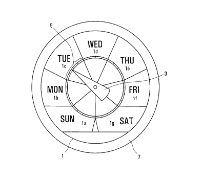
In Figure 1 there is a wedge-shaped indicator (3) in
the form of a pointer and a substantially circular display (1)
divided into seven essentially equally spaced areas (la to lg)
representing the days of the week. Each area has an
abbreviation of the day of the week printed therein. The areas
are arranged such that the days of the week read essentially
from left-to-right (clockwise) from Sunday (la) to Saturday
(lg). Wednesday (1d) it; located at: the top of the display (1).
This is considered to be: the most ergonomic arrangement since
CA 02313427 2000-07-28
13
most people in the North American culture consider Sunday to be
the first day of the wee k and read from left to right. Each
area is further subdivided into four regions (5) of
substantially equal size representing quarter days in order to
provide a more particular indication of the part of the day so
that more precise information can be had concerning activities
in a specific quarter of: the day. These regions are marked as
segments on a ring that is concentric with the outer edge of
the display.
An annular surface (7) disposed around the display
forms a rim on which notes may be posted. The indicator (3)
moves in a clockwise direction driven by a device comprising an
analog clock mechanism (see Figures 2A and 2B).
Figure 2A is a schematic side view of a device that
controls the movement of the indicator. An analog clock
mechanism (21) from a standard twelve-hour clock turns an hour
spindle (23) that is mounted on the clock mechanism. The hour
spindle turns a crank body (25) that is mounted on the hour
spindle. Two crank pins; (27a and 27b) are mounted on the crank
body and turn with the crank body. The crank pins are engaged
by a slotted wheel (29) that is forced to turn by the crank
pins when the crank body turns. An indicator spindle (31) is
mounted on the slotted wheel and turns with the slotted wheel.
An indicator (3) mounted on the indicator spindle turns with
the indicator spindle to give an indication of the day of the
week that is displayed on the display (1). Depending on
whether it is desired to move the indicator in a clockwise or
counter-clockwise dire~~tion, the clock mechanism can be rigged
to turn the hour spindle in a counter-clockwise or clockwise
direction.
In Figure 2A and Figure 2B, the hour spindle turns at
a rate of 14:1 when compared to the indicator spindle. Thus,
CA 02313427 2000-07-28
14
there are twenty-eight :lots in the slotted wheel to
accommodate the two crank pins. This arrangement permits the
indicator to pass a full_ 360 degrees around the circle in a one
week. Since the standard clock mechanism is on a half day
cycle, the 14:1 ratio requires the clock mechanism to turn the
hour spindle fourteen times in order to permit the two crank
pins to turn the indicator spindle one full revolution.
Two crank pins are not necessary. If one crank pin
is used, then there must: be fourteen slots in the slotted wheel
to turn the indicator spindle once for every fourteen
revolutions of the hour spindle. Any convenient combination
can be used. Two crank pins are preferred over one crank pin
since two crank pins inhibit the slotted wheel from wandering
which may be caused, for example, by vibrations in the tool.
The crank pins can be replaced by an appropriately
sized gear or gear system to maintain the 14:1 ratio when a
standard twelve hour clock mechanism is used. The slotted
wheel can be replaced by a gear or gear system, again provided
the correct ratio of 14:1 is maintained between the hour
spindle and the indicator spindle. The use of such gears would
make the indicator movement control device larger in the
present tool and may interfere with the design of the tool.
Using a crank pin system offers the advantage of requiring a
smaller slotted wheel than if gears are used. Therefore, a
crank pin system, especially one with two crank pins, is
preferred.
Figure 2B is a schematic of a partial transverse
section of the device depicted in Figure 2A to further clarify
how the parts of the device co-operate to move the indicator.
As the hour spindle (2.3) turns, the crank body (25) also turns
and the crank pins turn with the crank body. A crank pin (27b)
is engaged by a slot (33b) of the slotted wheel (29) in such a
CA 02313427 2000-07-28
manner that as the cram: body turns, the crank pin (27b) enters
slot (33b) forcing the slotted wheel to turn. At the same
time, the crank pin (27a) exits from slot (33a). As the crank
body turns one half revolution, the crank pin (27b) exits the
5 slot (33b) and crank pin (27a) enters the slot (33c) just
behind slot (33b) and the pattern is repeated.
The display (1_0) of Figure 3 is substantially semi-
circular in shape and .i~> divided into seven areas (l0a to lOg)
representing the days of= the week arranged in an essentially
10 left-to-right manner from Sunday (l0a) to Saturday (lOg). The
indicator (not shown) i:> a wedge-shaped pointer similar to that
in Figure 1 and moves in a counter-clockwise direction. An
apparatus comprising a set of pill containers (12) and a frame
(11) for holding the pil_1 containers is arranged along the
15 bottom edge of the display such that the pill containers sit in
front of the display. A second set of pill containers (13)
sits in front of the first set of pill containers (12). Both
the areas in the display and the pill containers are labelled
with abbreviations of the days of the week to facilitate
matching the day to the correct pill container.
The polygonal display (14) of Figure 4 is divided
into seven areas (14a tc> 14g) representing the days of the week
arranged in an essentially left-to-right manner (clockwise)
from Sunday (14a) to Saturday (14g). Each day of the week is
further subdivided into four regions (15) representing quarter
days in order to provide a more particular indication of the
part of the day so that more precise information can be had
concerning activities in a specific quarter of the day. The
indicator (not shown) ins a wedge-shaped pointer similar to that
of Figure 1 and moves in a clockwise direction. An apparatus
(16) comprising a surface for posting information is integrated
as part of the display (14).
CA 02313427 2000-07-28
16
The display (17) of Figure 5 is circular in shape and
is divided into seven az-eas (17a to 17g) representing the days
of the week arranged in an essentially right-to-left
(clockwise) manner from Sunday (17a) to Saturday (17g). The
indicator (not shcwn) is a wedge-shaped pointer similar to that
of Figure 1 and mcves in a clockwise direction. An apparatus
comprising a set cf ridges (18a to 18g) extending beyond the
display can be used to display information. For example, notes
or pill bottles or other informative elements can be attached
to the ridges and will hang into the appropriate area to
provide informaticn concerning a given day of the week. The
ridges may form an extension of the boundaries between the
areas and/or regicns of the display. In Figure 5, the ridges
form an extension of the boundaries between the areas of the
display.