Note: Descriptions are shown in the official language in which they were submitted.
CA 02313480 2000-06-09
WO 99/34189 PCT/US98/26450
POLARIZED GAS ACCUMULATORS AND HEATING JACKETS
AND ASSOCIATED GAS COLLECTION AND THAW METHODS AND
POLARIZED GAS PRODUCTS
This invention was made with Government support under AFSOR Grant
number F41624-97-C-9001. The United States Government has certain rights in
this
invention.
Field of the Invention
The present invention relates to the collection and accumulation of polarized
noble gases, and relates more particularly to the production of hyperpolarized
gases
for use in medical diagnostic procedures such as magnetic resonance imaging
("MRI") and spectroscopy applications.
Background of the Invention
Conventionally, MRI has been used to produce images by exciting the nuclei
of hydrogen molecules (present in water protons) in the human body. However,
it has
recently been discovered that polarized noble gases can produce improved
images of
certain areas and regions of the body which have heretofore produced less than
satisfactory images in this modality. Polarized Helium 3("3He") and Xenon-129
("129Xe") have been found to be particularly suited for this purpose.
Unfortunately, as
will be discussed further below, the polarized state of the gases is sensitive
to
handling and environmental conditions and can, undesirably, decay from the
polarized
state relatively quickly.
Hyperpolarizers are used to produce and accumulate polarized noble gases.
Hyperpolarizers artificially enhance the polarization of certain noble gas
nuclei (such
as 129Xe or 3He) over the natural or equilibrium levels, i.e., the Boltzmann
polarization. Such an increase is desirable because it enhances and increases
the
1
CA 02313480 2000-06-09
WO 99/34189 PCT/US9&126450
Magnetic Resonance Imaging ("MRI") signal intensity, allowing physicians to
obtain
better images of the substance in the body. See U. S. Patent No. 5,545,396 to
Albert
et al., the disclosure of which is hereby incorporated herein by reference as
if recited
in full herein.
In order to produce the hyperpolarized gas, the noble gas is typically blended
with optically pumped alkali metal vapors such as rubidium ("Rb"). These
optically
pumped metal vapors collide with the nuclei of the noble gas and hyperpolarize
the
noble gas through a phenomenon known as "spin-exchange". The "optical pumping"
of the alkali metal vapor is produced by irradiating the alkali-metal vapor
with
circularly polarized light at the wavelength of the first principal resonance
for the
alkali metal (e.g., 795 nm for Rb). Generally stated, the ground state atoms
become
excited, then subsequently decay back to the ground state. Under a modest
magnetic
field (10 Gauss), the cycling of atoms between the ground and excited states
can yield
nearly 100% polarization of the atoms in a few microseconds. This polarization
is
generally carried by the lone valence electron characteristics of the alkali
metal. In
the presence of non-zero nuclear spin noble gases, the alkali-metal vapor
atoms can
collide with the noble gas atoms in a manner in which the polarization of the
valence
electrons is transferred to the noble-gas nuclei through a mutual spin flip
"spin-
exchange".
Conventionally, lasers have been used to optically pump the alkali metals.
Various lasers emit light signals over various wavelength bands. In order to
improve
the optical pumping process for certain types of lasers (particularly those
with broader
bandwidth emissions), the absorption or resonance line width of the alkali
metal can
be made broader to more closely correspond with the particular laser emission
bandwidth of the selected laser. This broadening can be achieved by pressure
broadening, i.e., by using a buffer gas in the optical pumping chamber.
Collisions of
the alkali metal vapor with a buffer gas will lead to a broadening of the
alkali's
absorption bandwidth.
For example, it is known that the amount of polarized t29Xe which can be
produced per unit time is directly proportional to the light power absorbed by
the Rb
vapor. Thus, polarizing 129Xe in large quantities generally takes a large
amount of
laser power. When using a diode laser array, the natural Rb absorption line
c
bandwidth is typically many times narrower than the laser emission bandwidth.
The
2
CA 02313480 2000-06-09
WO 99/34189 PCTNS98/26450
Rb absorption range can be increased by using a buffer gas. Of course, the
selection
of a buffer gas can also undesirably impact the Rb-noble gas spin-exchange by
potentially introducing an angular momentum loss of the alkali metal to the
buffer gas
rather than to the noble gas as desired.
In any event, after the spin-exchange has been completed, the hyperpolarized
gas is separated from the alkali metal prior to introduction into a patient.
Unfortunately, after and during collection, the hyperpolarized gas can
deteriorate or
decay relatively quickly (lose its hyperpolarized state) and therefore must be
handled,
collected, transported, and stored carefully. Thus, handling of the
hyperpolarized
gases is critical, because of the sensitivity of the hyperpolarized state to
environmental and handling factors and the potential for undesirable decay of
the gas
from its hyperpolarized state.
Some accumulation systems employ cryogenic accumulators to separate the
buffer gas from the polarized gas and to freeze the collected polarized gas.
Unfortunately, reductions in polarization of the gas can be problematic as,
after final
thawing of the frozen gas, the polarization level of the gas can potentially
be
undesirably reduced by as much as an order of magnitude. Further and
disadvantageously, the extremely low operating temperatures of the accumulator
near
the cryogen source can sometimes clog the collection area of the accumulator,
thereby
decreasing the rate of, or even preventing, further collection.
Objects and S of the Invention
In view of the foregoing, it is therefore an object of the.present invention
to
extend the polarization life of collected polarized noble gases and to reduce
the
amount of de-polarization in the collected polarized gas prior to the end use
point.
It is another object of the present invention to provide an improved cryogenic
accumulator which can be used in a substantially continuous production
environment.
It is a further object of the present invention to provide an improved
collection
device and method which reduces the amount of polarization lost during
processing.
It is yet another object of the invention to provide a method which will
minimize the de-polarization effects attributed to thawing a frozen polarized
gas
product prior to delivery to an end user.
3
CA 02313480 2000-06-09
WO 99/34189 PCT/US98l26450
These and other objects are satisfied by the present invention by a cryogenic
accumulator with an internal heating jacket. In particular, a first aspect of
the
invention is directed to a cryogenic accumulator for collecting polarized
noble gases
which includes a primary flow channel having opposing first and second ends
configured to direct polarized gas therethrough, and an outer sleeve
positioned around
the primary flow channel. The outer sleeve has a closed end defining a
collection
chamber positioned below the flow channel second end. The accumulator also
includes a secondary flow channel positioned intermediate of the primary flow
channel and the outer sleeve. The secondary flow channel has a closed end
positioned
in close proximity to the primary flow channel second end.
In a preferred embodiment, the outer sleeve and the outer wall of the
secondary flow channel define a buffer gas exit channel therebetween and the
(circumferentially extending) inner wall of the secondary flow channel defines
the
primary flow channel. It is also preferred that the primary flow channel
second end
be configured as a nozzle and that the secondary flow channel be configured as
a
warnning or heating jacket to direct circulating room temperature dry gases
such as
nitrogen therethrough. The circulating nitrogen is separate from the flow
channel and
acts to compensate or protect the nozzle area against the cold buffer gas
exiting along
the outside of the primary flow channel and the cryogenic temperatures
associated
with the cryogen bath. Advantageously, such a secondary flow channel can
reduce
the likelihood that the primary flow nozzle will freeze and clog from
sublimation of
the noble gas.
Further and preferably, the accumulator includes first and second isolation
valves in communication with the primary flow channel and the buffer gas exit
channel. The first isolation valve is positioned at the first end of the
primary flow
channel and can be used to control the flow of a target gas therethrough. The
second
isolation valve is positioned spaced-apart from the outer sleeve closed end
along the
buffer gas exit channel to releasably seal and control the release of buffer
gas
therethrough. In this embodiment, the accumulator is configured to contain MRI-
sized quantities (such as 0.5-2 liters of polarized gas) and is detachably
releasable
from a hyperpolarizer unit for easy transport to a remote site.
Another aspect of the present invention relates to a heating jacket for a
refrigerated accumulator. The jacket includes an outer wall having opposing
first and
4
CA 02313480 2000-06-09
WO 99/34189 PCT/US98/26450
second ends and an inner wall having opposing first and second ends. The inner
wall
is spaced apart from the outer wall. The inner wall is configured to be in
close
proximity to a polarized gas collection path. The jacket also includes a top
and
bottom which bridge and seal each of the outer and inner walls. The top,
bottom and
outer and inner walls define at least one enclosed fluid (such as a gas or
liquid)
circulation channel therebetween. The jacket also includes a fluid and a fluid
vent,
each of which is in communication with the circulation channel. The fluid
inlet and
vent are configured to allow flow of a fluid, gas, or gas mixture in the
circulation
channel.
In a preferred embodiment, the heating jacket fluid inlet is operably
associated
with a valve such that it is configured to provide a predetermined flow rate
of the gas
in the circulation channel. It is also preferred that the inner wall
circumferentially
extends around a center opening to define a flow channel therethrough for a
polarized
gas.
It is additionally preferred that the inner wall include a first portion which
defines a flow channel first diameter and a stepped down. portion which
defines a flow
channel second diameter. In this embodiment, the second diameter is smaller
than the
first diameter and defines a flow channel nozzle.
Yet another aspect of the instant invention is directed to an accumulator for
collecting a polarized gas. The accumulator comprises a primary flow channel
having
opposing inlet and exit ends, with the exit end being configured as a flow
nozzle. The
inlet end is detachably connected to a polarized gas collection path. The
accumulator
also includes an outer sleeve with a collection chamber aligned with and
positioned
adjacent to the flow nozzle. In a preferred embodiment, the accumulator
includes a
heat source such as the enclosed heating jacket as described above. In
operation, the
heat source is arranged in the device to heat the flow nozzle to prevent
clogging or
freezing of the polarized gas thereat. An accumulator with a nozzle in the
primary
flow path can help remove and trap all of the hyperpolarized gas from the
inlet
stream, reducing any waste of exiting polarized gases. The use of a nozzle
improves
localization of polarized gases such as 129Xe. Further, such a nozzle can
minimize the
heat load on accumulated 129Xe (thus lengthening its relaxation or decay
time). The
use of a warming jacket can allow the use of a nozzle in the cryogen flow area
and
5
CA 02313480 2000-06-09
WO 99/34189 PCT/US98/26450
can improve the operation or function of the nozzle by reducing any clogging
in the
nozzle area of the flow path.
An additional aspect of the present invention is directed to a method for
collecting polarized noble gases. The method includes directing a gas mixture
comprising a polarized noble gas into a collection path. The gas mixture is
received
into an accumulator positioned in the collection path. The accumulator has an
inlet
channel, a collection reservoir, and an exit channel. The collection reservoir
is
exposed to temperatures below the freezing point of the polarized noble gas.
The
polarized noble gas is trapped in a substantially frozen state in the
collection reservoir.
The remainder of the gas mixture is routed into the exit chaninel. A portion
of the
collection path is heated or warmed to facilitate the flow of the gas mixture
therethrough. Preferably, the heating step includes the steps of introducing a
gas
separate from the gas mixture into a predetermined area of the inlet path, the
predetermined area being contained apart from the inlet path. The gas is
circulated
separate from the gas mixture about a portion of the inlet path to provide
conductive
heat to at least a portion of the inlet path and thereby reduce the likelihood
blockage
along the inlet path attributed to the exposing step. Preferably, the heating
is provided
by circulating room temperature N2 gas around the outside of at least a
portion of the
inlet path channel. The N2 gas is then captured and vented to atmosphere away
from
the frozen accumulated noble gas.
Yet another aspect of the present invention is a method of thawing frozen
polarized gas. In this method, a sealed container is provided. The container
has an
interior flow path and a collection chamber, the collection chamber is
configured to
hold frozen polarized gas therein. The frozen polarized gas is exposed to a
magnetic
field. A portion of the interior flow path adjacent the collection chamber is
heated
and the exterior of the sealed container is heated. Preferably, the thawing
step is
performed under pressure such that a substantial portion of the frozen noble
gas is
liquified during thawing of the frozen polarized gas. In a preferred
embodiment, the
container includes two valves, and after the frozen product is liquified, at
least one of
the valves is opened to decrease the pressure in the container causing the
liquified gas
to rapidly become gaseous. At this point, the flow of the gas is preferably
directed to
a patient. This step is typically accomplished by collecting the gas in a bag
or other
type of receptacle and delivering it to the patient. This method quickly thaws
the
6
CA 02313480 2000-06-09
WO 99134189 PCT/US98126450
frozen gas and minimizes the time the polarized gas spends in the transition
phase
which can improve the polarization levels retained upon thaw. Further, the
instant
thawing method can decrease the thawing time over conventional methods to less
than
seconds for single patient MRI doses. In a preferred embodiment, the 129Xe gas
5 mixture which is introduced into the polarizer includes a minimal amount of
131Xe to
minimize decay associated with the 1 " Xe induced relaxation of the 129Xe
isotope.
Yet another aspect of the present invention relates to a method of extending
the useful polarized life of a polarized gas product. The method includes the
steps of
providing a magnetic field and freezing a polarized gas in the presence of the
10 magnetic field. The polarized gas is sealed in a containment device or
vessel. The
frozen polarized gas is then thawed at a desired time. A substantial portion
of the
frozen gas is liquified under pressure in the sealed container. Preferably,
the thawing
step includes the heating steps as described above (heating both an interior
and
exterior of the sealed container). In any event, in one embodiment, the
containment
device is depressurized causing the liquid to become gas. More preferably, the
depressurizing step is carried out by opening the containment device to a
collection
vessel and allowing the liquid to expand into a gas phase during delivery of
the
polarized gas to an end user.
Advantageously, such a method can increase the polarization level in the
thawed polarized gas over conventional processing methods. Indeed, the instant
invention can double the polarization levels retained in gas samples processed
by
conventional methods. Further and additionally advantageously, the instant
invention
provides an improved accumulator which can improve the accumulation and the
preservation of the hyperpolarized state of the noble gas. Conventional
thawing and
accumulation techniques significantly reduced polarizations below predicted
values
(typically to about only 12.2% from its starting polarization levels at 900
sccm-
losing 87.8% of its starting polarization). The instant invention can improve
the
preservation of the polarization substantially. For example, the improved
accumulation and thawing methods can retain at least 30% or more (and
preferably
about 40%-50%) post-thaw polarization from the initial pre-frozen polarization
levels
("the polarization retention fraction"). Further, the instant invention can
provide
polarization levels at 10% or more at the time of delivery to a patient or end
user. In
addition, the instant invention can collect additional amounts of polarized
gas in a
7
CA 02313480 2006-11-10
30626-13
period by improving the delivery path and reducing the
potential of the cold finger to block with frozen gas and
the like during collection.
According to one aspect of the present invention,
there is provided a method of extending the useful
polarization life of a polarized noble gas product,
comprising the steps of: providing a magnetic field;
freezing a polarized noble gas; sealing the frozen polarized
noble gas in a containment device to collect a quantity of
frozen polarized gas therein; thawing the polarized noble
gas in the presence of the magnetic field; and converting a
substantial quantity of the frozen noble gas directly into a
liquid phase in the sealed container during said thawing
step.
The foregoing and other objects and aspects of the
present invention are explained in detail herein.
Brief Description of the Drawings
Figure 1 is a schematic illustration of a
hyperpolarizer apparatus according to one embodiment of the
present invention.
Figure 2 is a side perspective view of an
accumulator or "cold finger" of the apparatus of Figure 1
partially immersed in a liquid cryogen according to one
embodiment of the present invention.
Figure 3 is a cross-sectional side view of an
accumulator of Figure 2 according to one embodiment of the
present invention.
Figure 4 is a front view of the accumulator
illustrated in Figure 3.
8
CA 02313480 2006-11-10
30626-13
Figure 5 is a cross-sectional side view of an
additional embodiment of an accumulator of the present
invention.
Figure 6 is a partial cutaway perspective view of
the accumulator illustrated in Figure 3.
Figure 7 is a partial cutaway perspective view of
the accumulator illustrated in Figure 5.
Figure 8 illustrates the accumulator of Figure 7
with heat applied during a thawing process according to one
embodiment of the present invention.
Figure 9 is a block diagram illustrating the steps
of a method for accumulating polarized gas according to the
present invention.
Figure 10 is a block diagram illustrating the
steps of a method for thawing frozen polarized gas according
to one embodiment of the present invention.
Figure 11 is a block diagram illustrating the
steps of a method for extending the useful life of a
polarized gas according to one embodiment of the present
invention.
Figure 12A graphically illustrates polarization
levels after thaw versus accumulation flow rates of a
polarized thawed using a conventional thaw method.
8a
CA 02313480 2000-06-09
WO 99/34189 PCT/US98/26450
Figure 12B graphically illustrates exemplary polarization levels after thaw
versus accumulation flow rates of a polarized gas thawed according to the
present
invention.
Figure 13 graphically illustrates exemplary polarization levels of polarized
gas before freezing and after thawing according to the present invention.
Figure 13A graphically illustrates predicted and experimental exemplary
polarization levels of polarized xenon corresponding to the polarization flow
rate for
post-thaw experimental data taken when the xenon is processed according to the
present invention.
Detailed Descrintion of the Preferred Embodiments
The present invention will now be described more fully hereinafter with
reference to the accompanying figures. in which preferred embodiments of the
invention are shown. This invention may, however, be embodied in many
different
forms and should not be construed as limited to the embodiments set forth
herein.
Like numbers refer to like elements throughout. Layers and regions may be
exaggerated for clarity. In the description of the present invention that
follows,
certain terms are employed to refer to the positional relationship of certain
structures
relative to other structures. As used herein the term "forward" and
derivatives thereof
refer to the general direction the gas mixture travels as it moves through the
hyperpolarizer unit; this term is meant to be synonymous with the term
"downstream"
which is often used in manufacturing environments to indicate that certain
material
being acted upon is farther along in the manufacturing process than other
material.
Conversely, the terms "rearward" and "upstream" and derivatives thereof refer
to the
directions opposite, respectively, the forward and downstream directions.
Also, as
described herein, polarized gases are collected, frozen, thawed, and used in
MRI
spectroscopy or 1vIRI applications. For ease of description, the term "frozen
polarized
gas" means that the polarized gas has been frozen into a solid state. The term
"liquid
polarized gas" means that the polarized gas has been or is being liquefied
into a liquid
state. Thus, although each term includes the word "gas", this word is used to
name
and descriptively track the gas which is produced via a hyperpolarizer to
obtain a
polarized "gas" product. Thus, as used herein, the term gas has been used in
certain
places to descriptively indicate a hyperpolarized noble gas product and may be
used
9
CA 02313480 2000-06-09
WO 99/34189 PCT/US98/26450
with modifiers such as solid, frozen, and liquid to describe the state or
phase of that
product.
Various techniques have been employed to accumulate and capture polarized
gases. For example, U.S. Patent No. 5,642,625 to Cates et al., describes a
high
volume hyperpolarizer for spin polarized noble gas and U.S. Patent Application
No.
08/622,865 to Cates et al. describes a cryogenic accumulator for spin-
polarized 129Xe.
These references are hereby incorporated by reference as if recited in full
herein. As
used herein, the terms "hyperpolarize" "polarize", and the like, mean to
artificially
enhance the polarization of certain noble gas nuclei over the natural or
equilibrium
levels. Such an increase is desirable because it allows stronger imaging
signals
corresponding to better MRI images of the substance and a targeted area of the
body.
As is known by those of skill in the art, hyperpolarization can be induced by
spinr
exchange with an optically pumped alkali-metal vapor or alternatively by
metastability exchange. See Albert et al., U.S. Patent No. 5,545,396.
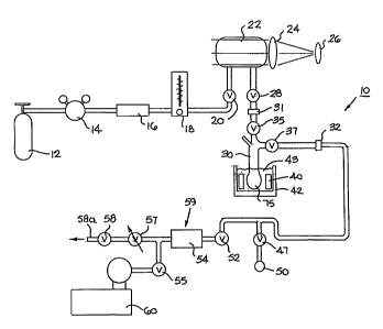
Referring to the drawings, Figure 1 illustrates a preferred hyperpolarizer
unit
10. This unit is a high volume unit which is configured to continually produce
and
accumulate spin-polarized noble gases, i.e., the flow of gas through the unit
is
substantially continuous. As shown, the unit 10 includes a noble gas supply 12
and a
supply regulator 14. A purifier 16 is positioned in the line to remove
impurities such
as water vapor from the system as will be discussed further below. The
hyperpolarizer unit 10 also includes a flow meter 18 and an inlet valve 20
positioned
upstream of the polarizer cell 22. An optic light source such as a laser 26
(preferably
a diode laser array) is directed into the polarizer cell 22 through various
focusing and
light distributing means 24, such as lenses, mirrors, and the like. The light
source is
circularly polarized to optically pump the alkali metals in the cel122. An
additional
valve 28 is positioned downstream of the polarizer cell 22.
Next in line, as shown in Figure 1, is a cold finger or accumulator 30. The
accumulator 30 is connected to the hyperpolarizer unit 10 by a pair of
releasable
mechanisms such as threaded members or quick disconnects 31, 32. This allows
the
accumulator to be easily detached, removed, or added, to and from the system
10.
The accumulator 30 is operably associated with a cold source or refrigeration
means
42. Preferably, and as shown, the cold source 42 is a liquid cryogen bath 43.
The
accumulator will be discussed in more detail hereinbelow.
CA 02313480 2000-06-09
WO 99/34189 PCT/US98/26450
A vacuum pump 60 is in communication with the system. Additional valves
to control flow and direct exit gas are shown at various points (shown as 52,
55). A
shut-off valve 47 is positioned adjacent an "on-board" exit gas tap 50.
Certain of the
valves downstream of the accumulator 30 are used for "on-board" thawing and
delivery of the collected polarized gas as will be described further below.
The system
also includes a digital pressure transducer 54 and a flow control means 57
along with
a shut-off valve 58. The shut-off valve 58 preferably controls the flow of gas
through
the entire system or unit 10; it is used to turn the gas flow on and off, as
will be
described below. As will be understood by those of skill in the art, other
flow control
mechanisms, devices (analog and electronic) may be used within the scope of
the
present invention.
In operation, a gas mixture is introduced into the system at the gas source
12.
As shown in Figure 1, the source 12 is a pressurized gas tank which holds a
pre-
mixed gas mixture. The gas mixture includes a lean noble and buffer gas
mixture gas
(the gas to be hyperpolarized is present as a relatively small amount in the
premixed
gas mixture). Preferably, for producing hyperpolarized 129Xe, the pre-mixed
gas
mixture is about 95-98% He, about 5% or less 129Xe, and about 1% N2.
It is also preferred that the pre-mixed gas mixture comprises a minimal
amount of the xenon -131 (or 131 Xenon) isotope (reduced from its natural
levels). In
nature, the typical xenon isotopic abundances are as follows:
Table I
Isotope Abundance Nuclear Spin
Xe 0.1% 0
e 0.09% 0
Xe 1.91% 0
Xe 26.4% '/s
13 e 4.1% 0
Xe 21.2% 3/2
Xe 26.9% 0
e 10.4% 0
e 8.9% 0
"Enriched" 129Xe mixtures are used to provide sufficient amounts of the 129Xe
gas for
the hyperpolarized gas mixture. As used herein, the form "enriched" means
increasing the abundance of 129Xe over its natural abundance level. However,
the
11
CA 02313480 2000-06-09
WO 99/34189 PCT/US9826450
enriched 129Xe typically also includes other Xenon isotopes. Unfortunately, at
least
one particular isotope -131Xe can interact with frozen "9Xe (particularly at
low
temperatures such as 4.2 K) in a manner which can cause the 129Xe to
depolarize. At
low temperatures, the 13'Xe acts like a' spin-sink" to absorb or decay the
129Xe
polarization and becoming a potentially dominant relaxation mechanism at the
crystal
grain boundaries of the frozen "solid" 129Xe polarized gas.
As shown in Table I above, 131Xe is an isotope with a nuclear spin greater
than
one-half. As such, it has a "quadruple moment" which means that 131Xe is able
to
relax by interacting with electric field gradients. See Gatzke et al.,
Extraordinarily
slow nuclear spin relation in frozen laser-polarized 129Xe, Phys. Rev. Lett.
70, pp.
690-693 (1993).
It has been suggested that at 4.2 K, the dominant solid phase relaxation
mechanism is "cross-relaxation" between the '29Xe and 131 Xe isotopes at the
crystal
grain boundaries. In addition, where the "frozen" or "solid" 129Xe gas takes
on a form
similar to a flake (such as a snowflake) the form has a relatively large
surface area.
Unfortunately, this relatively large surface area can also allow greater
depolarizing
interactions with the 131Xe. It is believed that the greatest or "most-
eiI=icient"
interchange is at the crystal grain boundaries because that is typically where
the
electric fields are strongest. This electric field strength can then allow the
131Xe
nuclear spin flip energy to become nearly the same as the 12yXe nuclear spin
flip
energy.
Examples of enriched 129Xe mixtures with a reduced 13'Xe isotope content are
given below.
Example 1 82.3% Enriched 129Xe Gas Mixture.
Isotope Abundance Nuclear Spin
Xe 0.47% 0
e 0.43% 0
e 8.41% 0
e 82.3% V2
e 4.52% 0
Xe 3.45% 3/2
Xe 0.36% 0
e 0.01% 0
e 0.01% 0
12
CA 02313480 2000-06-09
WO 99/34189 PCT/US9SR6450
Example 2 47.2% Enriched 129Xe Gas Mixture.
Isotope Abundance Nuclear Spin
124 Xe 0.14% 0
e 0.28% 0
1Xe 52.0% 0
Xe 47.2% 'h
e 0.22% 0
Xe 0.09% 3/2
132 Xe 0.03% 0
P Xe 0.02% 0
e 0.02% 0
In a preferred embodiment, when the collected polarized 129Xe will be exposed
to cold temperatures and frozen, the enriched 129Xe gas mixture preferably
includes
less than about 3.5% 131Xe, and more preferably less than about 0.1 % 131Xe.
In any event, the gas "enriched" mixture is passed through the purifier 16 and
introduced into the polarizer ce1122. The valves 20, 28 are on/off valves
operably
associated with the polarizer ce1122. The gas regulator 14 preferably steps
down the
pressure from the gas tank source 12 (typically operating at 13,780.2kPa (2000
psi or.
136 atm)) to about 608 - 1013.25 kPa (6-10 atm) for the system. Thus, during
accumulation, the entire manifold (conduit, polarized cell, accumulator, etc.)
is
pressurized to the cell pressure (about 608 - 1013.25 kPa (6-10 atm)). The
flow in the
unit 10 is activated by opening valve 58 and is controlled by adjusting the
flow
control means 57.
The typical residence time of the gas in the cell 22 is about 10-30 seconds;
i.e.,
it takes on the order of 10-30 seconds for the gas mixture to be
hyperpolarized while
moving through the ce1122. The gas mixture is preferably introduced into the
ce1122
at a pressure of about 608 - 1013.25 kPa (6-10 atm). Of course, with hardware
capable of operating at increased pressures, operating pressures of above
1013.25 kPa
(10 atm), such as about 2026.5- 3039.75 kPa (20-30 atm) are preferred to
pressure
broaden the Rb and absorb up to 100% of the optical light. In contrast, for
laser
linewidths less than conventional linewidths, lower pressures can be employed.
The
polarizer cell 22 is a high pressure optical pumping cell housed in a heated
chamber
with apertures configured to allow entry of the laser emitted light.
Preferably, the
hyperpolarizer unit 10 hyperpolarizes a selected noble gas such as 129Xe (or
3He) via a
conventional spin-exchange process. A vaporized alkali metal such as rubidium
13
CA 02313480 2000-06-09
WO 99/34189 PCT/US98/26450
("Rb") is introduced into the polarizer ce1122. The Rb vapor is optically
pumped via
an optic light source 26, preferably a diode laser.
The unit 10 employs helium buffer gas to pressure broaden the Rb vapor
absorption bandwidth. The selection of a buffer gas is important because the
buffer
gas -- while broadening the absorption bandwidth -- can also undesirably
impact the
alkali metal-noble gas spin-exchange by potentially introducing an angular
momentum loss of the alkali metal to the buffer gas rather than to the noble
gas as
desired. In a preferred embodiment, 129Xe is hyperpolarized through spin
exchange
with the optically pumped Rb vapor. It is also preferred that the unit 10 uses
a helium
buffer gas with a pressure many times greater than the 129Xe pressure for
pressure
broadening in a manner which minimizes Rb spin destruction.
As will be appreciated by those of skill in the art, Rb is reactive with H20.
Therefore any water or water vapor introduced into the polarizer cell 22 can
cause the
Rb to lose laser absorption and decrease the amount or efficiency of the spin-
exchange in the polarizer ce1122. Thus, as an additional precaution, an extra
filter or
purifier (not shown) can be positioned before the inlet of the polarizer cell
22 with
extra surface area to remove even additional amounts of this undesirable
impurity in
order to further increase the efficiency of the polarizer.
Hyperpolarized gas, together with the buffer gas mixture, exits the polarizer
cell 22 and enters the accumulator 30. Referring now to Figures 3-7. the
polarized
gas and buffer gas are directed down a primary flow path 80 and into a
collection
reservoir 75 located at the bottom of the accumulator 30. In operation, at the
lower
portion of the accumulator 30a, the hyperpolarized gas is exposed to
temperatures
below its freezing point and collected as a frozen product 100 in the
reservoir 75. The
remainder of the gas mixture remains gaseous and exits the primary flow path
80 and
the reservoir 75 by counterflowing in an exit path 90 different from the
primary flow
path 75 such that it is directed out of the accumulator 30. The accumulator 30
will be
discussed in more detail below. The hyperpolarized gas is collected (as well
as
stored, transported, and preferably thawed) in the presence of a magnetic
field,
generally on the order of at least 500 Gauss, and typically about 2kiloGauss,
although
higher fields can be used. Lower fields can potentially undesirably increase
the
relaxation rate or decrease the relaxation time of the polarized gas. As shown
in
14
CA 02313480 2000-06-09
WO 99/34189 PCT/US98/26450
Figure 2, the magnetic field is provided by permanent magnets 40 positioned
about a
magnetic yoke 41.
The hyperpolarizer unit 10 can also use the temperature change in the outlet
line between the heated pumping cel122 and the refrigerated cold trap or
accumulator
30 to precipitate the alkali metal from the polarized gas stream in the
conduit above
the accumulator 30. As will be appreciated by one of skill in the art, the
alkali metal
can precipitate out of the gas stream at temperatures of about 40 C. The unit
can also
include an alkali metal reflux condenser (not shown). Preferably, the
refluxing
condenser employs a vertical refluxing outlet pipe, which is kept at room
temperature.
The gas flow velocity through the refluxing pipe and the size of the refluxing
outlet
pipe is such that the alkali metal vapor condenses and drips back into the
pumping
cell by gravitational force. In any event, it is desirable to remove the
alkali metal such
that the product is non-toxic and comply with regulatory standards (for
example at
least to a level at or below 10 ppb) prior to delivering polarized gas to a
patient.
Optionally, an intermediate cold trap can also be positioned between the exit
of the polarizer cell 22 and the cold finger 30. The temperature of the
intermediate
cold trap (not shown) will preferably be designed to trap out any alkali metal
(e.g. Rb)
while leaving the noble gas and carrier gas (es) free to reach the cold finger
30. This
can be important for in vivo applications where it is important to remove the
Rb from
the hyperpolarized gas (i.e., remove the Rb to a level such that no more than
trace
amounts such as on the order of one ppb or less remains in the hyperpolarized
gas
when delivered to a patient).
Once a desired amount of hyperpolarized gas has been collected in the
accumulator 30, the accumulator can be detached or isolated from the system.
In a
preferred embodiment, valve 28 is closed, leaving the cel122 pressurized. This
allows
the accumulator 30 and the downstream plumbing to begin to depressurize
because
the flow valve 58 is open. Preferably, the unit 10 downstream of the valve 28
is
allowed to depressurize to about 1.5 atm before the flow valve 58 is closed.
After
closing the flow valve 58, valve 55 can be opened to evacuate the remaining
gas in
the manifold. Once the outlet plumbing is evacuated, valves 35 and 37 are
closed. If
the collected gas is to be distributed "on board", i.e., without removing the
accumulator 30 from the unit 10, a receptacle such as a bag or other vessel
can be
attached to the outlet 50. The valve 47 can be opened to evacuate the attached
bag
CA 02313480 2000-06-09
WO 99/34189 PCTNS98/26450
(not shown). Once the bag is evacuated and the gas is ready to thaw, valve 52
can be
optionally closed. This minimizes the contact of the polarized gas with the
pressure
transducer region 59 of the unit 10. This region typically includes materials
that have
a depolarizing effect on the polarized gas. Thus, long contact times with this
region
may promote relaxation of the polarized gas.
If the valve 52 is not closed, then valve 55 is preferably closed to prevent
the
evacuation of polarized thawed gases. It is also preferred that the flow
channels on
the downstream side of the ce1122 are formed from materials which minimize the
decaying effect on the polarized state of the gas. Coatings can also be used
such as
those described in U.S. Patent No. 5,612,103, the disclosure of which is
hereby
incorporated by reference as if recited in full herein. In the "on-board" thaw
operation, valve 37 is opened to let the gas out. It then proceeds through
valve 47 and
exits outlet 50.
In the "detached" or "transported accumulator" thaw mode, accumulator fust
and second isolation valves 35, 37 are closed after the depressurization and
evacuation of the accumulator 30. Evacuating the accumulator 30 allows any
residual
gas in the accumulator to be removed. Leaving residual gas in the accumulator
30
with the frozen polarized gas may contribute to the heat load on the frozen
gas,
possibly raising the temperature of the frozen gas and potentially shortening
the
relaxation time. Thus, in a preferred embodiment, after depressurization and
evacuation and closing the isolation valves 35, 37, the accumulator 30 is
disconnected
from the unit 10 via release points 31, 32.
It is also preferred that the accumulator include 0-rings in grooves (Figure
2,
220) to assist in sealing the quick connects (or other attaching means) to the
conduit
lines in the system. This type of 0-ring/groove sealing mechanism can help
assure
the seals integrity even at the elevated operating pressures (i.e., 608 -
1013.25 kPa (6-
10 atm) and greater) of the unit. Similarly, if CHEM- THREADSTM (manufactured
by ChemGlass, Inc. Vineland, NJ) or similar attachment means are used, it is
preferred that they be configured to hold pressures consistent with the
operating
pressures of the system. Examples of suitable isolation valves 35, 37 include
KIMBLE KONTES Valves 826450-004, 826460-00041ocated in Vineland, NJ.
The isolation valves 35, 37 are in communication with the primary flow
channe180 and the buffer gas exit channe190 respectively and each can adjust
the
16
CA 02313480 2000-06-09
WO 99/34189 PCT/US98/26450
amount of flow therethrough as well as close the respective paths to isolate
the
accumulator from the system 10 and the environment. After the filled
accumulator 30
is removed, another accumulator can be easily and relatively quickly attached
to the
release points 31, 32. Preferably, when attaching the new accumulator 30, the
outlet
manifold is evacuated using valve 55 (with valves 52, 35, 37 open). When a
suitable
vacuum is achieved (such as about 13.3Pa (100mil1iTorr)) which typically
occurs
within about one minute or so, valve 55 is closed. Valve 28 is then re-opened
which
repressurizes the outlet manifold to the operating cell pressure. Valve 58 is
then
opened to resume flow in the unit 10. Preferably, once flow resumes, liquid
nitrogen
is applied to the accumulator 30 to continue collection of the hyperpolarized
gas.
Typically such a changeover takes on the order of less than about five
minutes. Thus,
a preferred hyperpolarizer unit 10 is configured to provide a continuous flow
of
hyperpolarized 129Xe gas for continuous production and accumulation of same.
Turning now to Figure 2, an accumulator and magnet yoke assembly 230 is
shown. The accumulator 30 is supported by a support platform 210 positioned
over
the cryogen bath 43. A pair of plates 215 longitudinally extend from the
support
platform 210 and connect to the magnet yoke 41. The magnet yoke 41 is
positioned
adjacent to and in close proximity to the collection reservoir 75 of the
accumulator 30
to provide the desired magnetic field to the collected polarized gas. As
shown, the
accumulator 30 includes a support contact portion 211, which is configured to
rest
against the support platform 210.
The Accumulator
Figures 3 and 4 show one embodiment of an accumulator 30 according to the
instant invention. As shown, the accumulator 30 includes a central primary
flow path
80, a secondary flow path 95, and an exit buffer gas channel 90. The secondary
flow
path or channel 95 is positioned intermediate of the primary flow path
channe180 and
the buffer exit channe190. In a preferred embodiment, the accumulator 30
includes a
nozzle 110 at the lower end of the primary flow path. The nozzle 110 can help
improve localization of the hyperpolarized gas as it impacts the cold surfaces
of the
reservoir 75. The nozzle 110 may also allow Joule-Thompson expansion of the
cooling of the gas stream to well below the freezing point of the
hyperpolarized gas,
advantageously minimizing the heat load on the stationary and collected
17
CA 02313480 2000-06-09
WO 99/34189 PCr/US9826450
hyperpolarized gas and thereby, potentially lengthening its relaxation time.
In any
event, the accumulator 30 is preferably immersed in the cryogen bath 43 such
that the
reservoir 75 and about 7.62-15.24 cm (3-6 inches) of the tube is immersed. If
submerged in liquid nitrogen, the exterior wall of the outer sleeve 103 and
the exterior
wall or the reservoir 75 will be at about 77 K. The freezing point of Xenon is
approximately 160 K. Thus, upon exiting the primary flow path 80, the
hyperpolarized gas hits the cold surface and freezes into the reservoir 75
while the
buffer gases exit the accumulator via the exit channel 90. The reservoir can
include a
surface coating to help prevent relaxation caused by the polarized gas's
contact with
same. See U.S. Patent No. 5,612,103, "Improved Coatings for the Production of
Hyperpolarized Noble Gases ". Alternatively, the container can be formed from
or
include other materials such as high purity non-magnetic metallic fiims. See
co-pending and co-assigned patent application Serial No. 09/126,448, entitled
Containers for Hyperpolarized Gases and Associated Methods, which is hereby
incorporated by reference as if recited in full herein.
As shown in Figure 4, the secondary flow path 95 has an inlet and outlet 125,
126, respectively, positioned about 180 apart at a top portion of the
accumulator 30.
Of course, as will be appreciated by one of skill in the art, alternative
arrangements of
the secondary flow path inlet and outlet 125, 126 can also be employed.
Preferably,
the inlet and outlet 125, 126 are configured to be above the cryogen bath 43
or other
refrigeration means when the accumulator 30 is assembled thereto. Except for
its
respective inlet and vent ports 125, 126, the secondary flow path 95 is
enclosed and
separate from the primary flow path 80 and the exit gas path 90. As such, the
secondary flow path 95 includes a sealed closed end 96.
In operation, as shown in Figure 6, the secondary flow path 95 provides heat
to a region of the accumulator 30. Preferably, the secondary flow path defines
a
heating jacket 93. The heating jacket 93 is configured to provide a contained
warm
stream of a fluid, preferably a gas, around the primary flow path 80. More
preferably,
the heating jacket 93 directs warm or ambient temperature nitrogen down the
secondary flow path to an area adjacent the lower portion of the primary path
80; that
is, the portion of the secondary path is in close proximity to or adjacent the
reservoir
75. In a preferred embodiment, the warming gas in the heating jacket 93 is
directed to
the nozzle 110 area of the primary flow path 80 via the secondary flow path
95.
18
CA 02313480 2000-06-09
WO 99/34189 PCT/US98/26450
Advantageously, such a warming gas can compensate for the undesirable tendency
of
this area of the primary flow path to freeze and clog due to frozen gases
trapped in the
flow path 80. Further and advantageously, this configuration can also minimize
any
associated heat load which is directed into the reservoir 75 and on the
collected frozen
polarized gas. The clogging problem can be particularly troublesome in
accumulators
with nozzle designs, as even small amounts of build up in the reduced exit
area of the
nozzle 110 can block the primary flow path 80 and decrease and even prevent
further
collection of polarized gas. "Warming" as used herein can be the application
of heat
at any temperature above the freezing point of selected polarized gas, i.e.
above
160 K for 129Xe.
Generally stated, the relaxation time of solid polarized gas (especially
129Xe) is .
strongly dependent on the temperature of the frozen gas. Stated differently,
the lower
the temperature of the frozen gas, the longer the relaxation time. Thus, it is
important
to minimize the heat load on the accumulated frozen gas. The heat load
presented by
the gas stream directed down the primary flow path 80 is largely attributed to
the need
to cool the buffer gas from room temperature to the cryogenic temperature (as
described herein liquid nitrogen (LN2) or 77 K. This heat load is estimated to
be on
the order of 2W. Thus, in order to minimize the heat load on the accumulated
polarized 129Xe, it is desirable to cool the gas steam to close to (but above)
the
freezing temperature of the polarized gas prior to the exit point of the
nozzle 110. For
129Xe, the buffer gas is preferably cooled to just above 160 K, below which
the Xe
can freeze in the nozzle potentially causing a clog or blockage.
Advantageously,
cooling the exit gas to 160 K can cut the heat load on the frozen polarized
gas by as
much as 50%. The configuration of the instant invention allows this exit
channel to
be so cooled through the counter-flow of the buffer gas. Advantageously, this
cooling
counter-flow does not overly expose the nozzle 110 to low temperatures because
the
nozzle 110 or most susceptible area of the flow path 80 is separated from the
exit
channel by the heating jacket or secondary flow channel 95.
Referring again to Figure 4. as shown, the primary flow path 80 is defmed by
the shape of the inner wall 93a of the heating jacket 93. Preferably, the
inner wall
93a circumferentially extends around an opening to define the primary flow
path 80.
Similarly, the outer wall 93b of the heating jacket 93 together with the outer
sleeve
103 of the accumulator 30 defmes the buffer exit path 90. As shown in Figure
6, in a
19
CA 02313480 2000-06-09
WO 99/34189 PCT/US98/26450
preferred embodiment, the inner wal193a, the outer wal193b and the outer
sleeve 103
are radially aligned. The inner wall of the heating jacket 93 includes a
stepped down
portion 193 with a diameter less than the diameter of the preceding section of
the
inner wall. This stepped down portion is configured to provide the nozzle 110
in the
primary flow path 80.
Figures 5 and 7 illustrate a preferred embodiment of an accumulator 30'
according to the instant invention. As shown in this embodiment, the heating
jacket
93 includes at least one elongated conduit 145 which extends along a major
portion of
the secondary flow path 95. As the conduit 145 is exposed to cryogenic
temperatures,
it should be made from suitable substantially non-depolarizing and cryo-
accepting
materials such as PTFE and the like. Suitable materials include materials
which have
a low temperature resistance. One example of a brand of such a material is
TEFLONT"" or metallic-film coated surfaces. The conduit 145 directs the
warming
gas down to the lower portion of the primary flow path 80, and more preferably
directs the watming gas to the nozzle area 110 of the primary flow channel
above the
reservoir 75. As such, the lower end 145a of the conduit is preferably
positioned
adjacent the nozzle 110. Once released, the warming gas travels up the
circumferentially extending secondary flow path 95 and exits at the outlet
vent 126.
This warming gas can counteract the cold/clogging effect the counter-flow of
the cold
buffer gas has on the primary flow path in the region susceptible to clogging
as
discussed above. Of course, additional heating jacket inlets, conduits, and
vents (not
shown) can also be employed within the scope of the invention.
Examples of suitable diameters of the primary flow path 80, the secondary
flow path 95, and the buffer gas exit channe190 are 6.35, 12.7, and 19.05mm
(0.25,
0.50, and 0.75 inches), respectively. In one embodiment the nozzle 110 extends
along
the primary flow path for about 25.4mm (1.0 inches). Preferably, the
accumulator 30
is formed from glass such as PYREXT"" and is configured to withstand from
about 608
-1013.25 kPa (6-10 atm) or more of pressure.
In operation, it is preferred that, during accumulation of frozen
hyperpolarized
gas, the warming gas is introduced into the secondary channel at a rate of
about
7.8658 -47.2 ml/s (1-6 ft3/hour), more preferably at the rate of about 15.732-
39.329
ml/s (2-5 flelhr), and still more preferably at a rate of about 23.597 ml/s (3
fe/hr).
CA 02313480 2000-06-09
WO 99/34189 PCT/US98/26450
Preferably, during collection, the accumulator 30 operates at the same
pressure as the
optical pumping cell.
As discussed above, the preferred warming gas is a dry ambient temperature
N2 (N2 has approximately two times the heat capacity of helium), but the
invention is
not limited thereto. Exemplary preferred temperatures of the warming gas are
from
about 10-26.7 C(50 -80 F), and more preferably from about 20-25.6 C(68 -78
F).
In a preferred embodiment, a corresponding "heating gas" flow rate is set to a
minimum level corresponding to a predetermined temperature of the warming gas;
i.e., the minimum rate is set for a certain temperature below which a clog
occurs, this
minimum rate can be termed the "critical flow rate '.. If higher temperatures
are used,
lower flow rates will typically be required. Examples of other warming gases
include,
but are not limited to, helium, dry air, and the like. Preferably, if higher
temperature
"warming" gases are used a lower corresponding flow rate is used. In contrast,
if
lower temperature "warming" gases are used then a higher corresponding flow
rate is
used.
Advantageously, the instant invention can collect about 80-100% of the
polarized gas in the gas stream. In addition, the instant invention can yield
a
polarized gas product with an extended useful life. This is attributed to the
improved
collection and/or thawing techniques which can yield a polarized gas product
which
retains greater polarization levels compared to conventional techniques as
will be
discussed fiuther below.
Thawing
As noted above, a preferred embodiment of the instant invention employs a
compact permanent magnet arrangement positioned around the hyperpolarized gas.
Unfortunately, the magnetic field provided by such an arrangement can be
somewhat
inhomogeneous. As gas is thawed, this inhomogeneity can depolarize the
hyperpolarized gas relatively quickly. Freshly thawed 129Xe is particularly
susceptible to inhomogeneity induced decay ("loss of polarization"). For
example,
relaxation of gaseous 129Xe is particularly troublesome as it diffuses through
inhomogeneous fields. This relaxation generally scales linearly with inverse
pressure
of the gas. That is, at low gas pressures, which occur at the beginning of the
thawing
21
CA 02313480 2000-06-09
WO 99/34189 PCT/US98/26450
process, the inhomogeneity (field gradients) induced relaxation effect is the
strongest.
(Relaxation of '29Xe at 101.325 kPa (1 atm) of gas pressure has been measured
at just
22 seconds). The instant invention solves this problem by closing the
isolating valves
35, 37 in the accumulator 30 during the initial thaw. As the polarized gas
thaws,
pressure builds up rapidly, quickly exceeding I atm and building further. As
the
pressure rises, the remaining solid 129Xe goes into liquid form rather than
gaseous
form. The liquid 129Xe is relatively insensitive to magnetic field gradients,
inhomogeneity relaxation, temperature effects, and magnetic field strengths,
thus
making it one of the more robust forms of hyperpolarized 129Xe. Liquid 129Xe
has
typical relaxation times of about 20-30 minutes. See K.L. Sauer et al., Laser
Polarized Liquid Xenon, Appl. Phys. Lett. (Accepted 1997). The liquid state
further
helps to quickly distribute heat to the remaining solid 129Xe, thus further
speeding the
thaw.
In a preferred embodiment, the heating jacket 93 can also improve the thawing
process of the frozen polarized gas. The instant invention recognizes that it
is
important to rapidly transform the frozen polarized gas into a liquid state as
both the
solid and the gas states of Xenon are extremely sensitive to depolarization
during the
transition. For example, as solid or frozen 129Xe is warmed to near its
melting point,
the relaxation time is dramatically reduced from 3 hours at 77 K to just a few
seconds
near the phase transition point. In addition, gaseous relaxation at
temperatures just
above the sublimation temperature of 129Xe is rapid, with an exponential
dependence
on temperature. For example, the relaxation time of gaseous 129Xe on a given
surface
at 160 K is only 3% as long as that at 300 K on the same surface. Further,
during the
early stages of thawing when the Xe gas pressure is low, the gaseous 129Xe is
more
susceptible to the inhomogeneity problems discussed above.
Conventionally, heat has been supplied to the exterior of the accumulator
during thawing. As the frozen hyperpolarized gas began to thaw it would freeze
again, such as on the exit point of the primary flow path 80. This could cause
the
129Xe to freeze and thaw more than once during the thawing process, as well as
causing the polarized gas product to spend more time around the sensitive
transition
phase where relaxation is more rapid.
Advantageously, the heating jacket 93 of the accumulator 30, 30' described
above can additionally improve the thawing process. Turning to Figure 8, the
heating
22
CA 02313480 2000-06-09
WO 99/34189 PCT/US98/26450
jacket or secondary flow channel 95 of the accumulator can supply heat to the
nozzle
area 110 of the accumulator 30 during the thawing process. Preferably the
lower area
of the flow path or the nozzle area is preheated before thawing so that the
nozzle 110
is well above the freezing point of the polarized gas prior to applying heat
to the
external surface of the reservoir 75. It is additionally preferred, that
during the
thawing, heat is supplied to both the exterior and the interior of the cold
finger. The
interior heating being preferably applied to the lower region of the
accumulator, i.e.,
the nozzle area. The nozzle 110 is thus warmed by the circulating fluid
(preferably
gas) in the heating jacket 93. Various warming gases such as those described
above
can be used. Preferably, the flow rate of the warming gas is higher than that
used
during the accumulation process, such as about 39.329 - 94.39 ml/s (5-12
ft3/hr), and
more preferably at about 78.658 mUs (10 ft3/hr) during thaw. Similarly, the
preferred
temperatures of the "warming" gas supplied during thawing are at typical
internally
controlled ambient conditions (for example room temperature gases such as 20-
25.6 C (68-78 F)).
For a"transported" accumulator 30, once all the 129Xe is liquid, the isolation
valve 35 is preferably opened leading to an attached evacuated chamber or bag
or
other delivery means or collection vessel. Of course either of the valves 35,
37 can be
opened depending on where the delivery vessel or receptacle is attached (not
shown).
For the "on-board" accumulator, isolation valve 37 is the operative valve as
described
above. The sudden decrease in pressure causes the liquid 129Xe to become
gaseous
and exit the accumulator 30 rapidly, advantageously thereby spending a minimum
amount of time in the inhomogeneous magnetic field in the gaseous state.
Similarly,
if the "on-board" release is employed, the isolation valve 37 is opened and
the gas
flows through valve 47 and exits outlet 50 into a delivery vessel.
Conventional
methods of thawing included opening the cold finger (accumulator) to the
vessel to be
filled and then starting the thaw. This thaw could typically take 30 seconds
or more
to complete for single patient dose amounts. In comparison and advantageously,
the
instant thaw method can be completed in less than about 10 seconds, and
preferably in
less than about 5-6 seconds for single dose amounts of frozen hyperpolarized
gas. A
typical patient dose is from about 0.20-1.25 liters ("L") and preferably about
0.5-1.0
L. The conversion weight is about 5.4 grams /L of Xe. Similarly, the density
of solid
23
CA 02313480 2000-06-09
WO 99/34189 PCT/US98/26450
Xe is about 3.1g/cm3, and a corresponding patient volume of polarized frozen
Xe can
be calculated at about 1.8cm3/L.
Advantageously, observations of the instant thawing method indicate a reliable
factor of about 2 or more improvement in the final polarization level of
thawed 129Xe
as compared to that thawed by conventional methods.
Referring now to Figures 12A and 12B, Figure 12A illustrates the
polarization results obtained by a conventional thaw technique while Figure
12B
graphically illustrates results obtained by the improved thaw method of the
instant
invention as described above. Each of the graphs plot % polarization of 129Xe
after
thaw in relationship to the total gas flow rate through the polarization
ce1122 (and
therefore the entire unit). The corresponding 129Xe flow rate is the % of the
total gas
mix. In the example shown, 129Xe makes up about 1% of the total gas mix, thus
the
129Xe-flow rate is the total flow rate divided by 100. For example at a flow
rate of
1000 standard cm3 (standard cubic centimeters per minute ("sccm")), 129Xe is
typically accumulated at the rate of 10 cm3 per min or 600 cm3 per hour.
Higher
flow rates are desired to increase the through-put of 129Xe. However,
polarization is
reduced at higher flow rates. This is attributed to the reduced time that the
129Xe
spends in residence time in spin exchange contact with the optically pumped Rb
at
higher flow rates. That is, the Xe residence time in the cel122 can generally
be
described mathematically as equal to the gas pressure multiplied by the cell
volume
divided by the flow rate
(PV / in).
Figure 12A shows the conventional thaw technique yields scattered
polarization results which are attributed to random polarization losses mainly
occurring during thawing. Figure 12B tracks with the optical pumping
characteristics
described above and now produces predictable post-thaw polarization levels
corresponding to the accumulation flow rate.
As shown in Figure 12B, when thawing according to the improved method
described above (under pressurization and with internal and external heating),
for
flow rates below 1000 sccm (or standard cm3/min), polarization levels after
thaw of
above 10% are reliably achieved. The results shown in this figure represent a
190 cm3
volume of 129Xe (and Rb polarization levels of about 0.25-0.49). Of course, as
will be
24
CA 02313480 2000-06-09
WO 99/34189 PCT/US98/26450
appreciated by one of skill in the art, different volumes (i.e., larger or
smaller) of the
polarized gas will have different relative values associated therewith. For
example,
larger volumes of 129Xe takes longer times to polarize, therefore at the same
flow
rates, the polarization of the larger volume will be less than that shown in
Figure
12B. Stated differently, for larger amounts of polarized gas, the associated
polarization curve will drop below the values shown relative to that for an
exemplary
190 cm3 volume of polarized gas as shown in Figure 12B. Also, typically,
larger
amounts of polarized gas can result in a larger loss attributed to solid-phase
relaxation. However, as shown by the graph, the instant invention now provides
a
frozen gas thaw method which results in a post-thaw polarization curve which
predictably follows the initial polarization curve. In contrast, as shown by
Figure
12A, the conventional polarization level after thaw is highly unpredictable,
with an
average of about 4.4%. Indeed, at about 900 sccm (standard cm3/min), the
polarization point is about 2.16% while prediction is 18.7%, thus making the
retention
fraction a low 12.2% (losing about 87.8% of the starting polarization). Unlike
the
conventional method, the instant invention produces polarization levels after
thaw that
predictably corresponds to the flow rate used during accumulation.
Figure 13 illustrates experimental and theoretical polarization levels before
and after thawing. The experimental flowing curve shows the polarization
levels
achieved before freezing (the level measured as the 129Xe exits the pumping
cell 22).
The experimental data points on the graph represent thawed data points
achieved by
thawing the collected, frozen polarized gas according to the present
invention. The
experimental data confirms that the methods of the instant invention improve
the
predictability of the polarization retention fraction now achievable as well
as
increases the value of the polarization retention fraction (amount of
polarization
retained post-thaw relative to that attained prior to freeze).
Figure 13A illustrates a flow curve used to predict polarization levels as
expected from a thawed polarized xenon product, this curve representing post-
thaw
polarization levels achievable absent polarization losses during freezing and
thawing.
This curve includes losses from nortnal relaxation of solid Xe (which can be
generally
estimated to be approximately 2 hours at 77 K). As shown, low flow rates
typically
have an associated relatively large polarization loss. This is because, at low
flow
rates, the accumulation time can be extensive and the ice "T 1" then plays a
larger or
CA 02313480 2000-06-09
WO 99/34189 pCT/US98/26450
more dominant role. As shown, the polarization retention fraction achieved
using the
freezing and thawing methods of the instant invention is above 40% for all
flow rates,
and the average is about 49.9%. Therefore, as shown in Figure 13A, this
polarization
retention fraction is substantially insensitive to flow rate. The below listed
data shows
exemplary polarization retention fractions now achievable.
Flow Rate Polarization (P) olm P exar. Retention Fraction
300 24 12.66 52.8%
600 22.1 11.18 50.6%
900 18.7 9.30 49.7%
1200 15.9 7.83 49.2%
1500 13.75 6.73 48.9%
1800 12.08 5.90 48.8%
2000 11.1 5.43 48.9%
For example, a data point at a flow rate of 600 sccm has a theoretical
polarization level of 22.1 and a corresponding experimental data point of
11.18
polarization after thaw. The initial polarization level (before-
accumulation/freezing)
for this flow rate is 22.1%. Therefore, the polarization retention fraction
after the
freeze/thaw process is 11.18/22.1 or 50.6%. Thus, advantageously, the instant
thawing technique retains at least 30% of the initial polarization level and
based on
this data preferably above 40% of the initial polarization level, and most
preferably
above 45%. Further the improved retention rate increases the thawed
polarization
level by an order of magnitude (now reliably and predictably above about 10%
in
contrast to conventional thawed polarization levels of about 2%).
Although particularly suited for 129Xe, the instant thawing method can also
successfully be employed with other hyperpolarized noble gases. Further, it
will be
appreciated by those of skill in the art, that the cryogen used to freeze the
polarized
gas is not limited to liquid N2. However, if alternate refrigeration sources
or cryogens
are used then flow rates, accumulation rates, "warming" gas temperatures and
the like
should be adjusted accordingly. Further, it is desired to use refrigeration
sources with
temperatures at least as low as liquid nitrogen (77K) for collection of the
polarized
gas. Lower temperatures increase the Tl time of the solid polarized gas which
results
in increased relaxation times. For example, polarized gases frozen at liquid
nitrogen
temperatures have an ice relaxation time (T1) of approximately 2.8 hours while
26
CA 02313480 2000-06-09
WO 99/34189 PCT/US98/26450
polarized gases frozen at liquid helium temperatures have an ice relaxation
time (Tl)
of approximately 12 days. Therefore, in order to achieve higher polarization
levels
after thawing, the thawing is preferably performed within the corresponding T1
time
period.
Figures 9, 10, and 11 are block diagrams of methods associated with the
instant invention. The order of the methods is not meant to be limited by the
block
numbers and order shown. Additional steps can also be included as
operationally
described hereinabove.
Figure 9 shows steps for accumulating or collecting frozen polarized gas
according to one embodiment of the instant invention A gas mixture comprising
a
polarized gas is directed into collection path (Block 900). The polarized gas
is
received into the accumulator in the collection path. The accumulator has an
inlet
channel, a collection reservoir, and an exit channel (Block 910). The
collection
reservoir is exposed to temperatures below the freezing point of the polarized
noble
gas (Block 920). The polarized gas is trapped in a substantially frozen state
in the
collection reservoir (preferably a total solid frozen state)(Block 930). The
remainder
of the gas mixture is routed into the exit channel (Block 940). A portion of
the inlet
channel in the accumulator is heated to facilitate the flow of the gas mixture
therethrough (Block 950). The heating step (Block 950) is preferably carried
out by
introducing a gas separate from the gas mixture to conductively heat a
predetermined
area of the inlet channel, the separate gas being contained apart from the
inlet and exit
paths. The contained separate gas is then circulated about a portion of the
inlet path
to reduce the likelihood of blockage along the inlet path attributed to the
exposing
step.
Figure 10 illustrates a method for thawing frozen polarized gas according to a
preferred embodiment of the present invention. A sealed container is provided
which
includes an interior flow path and a collection chamber for holding frozen
polarized
gas (Block 1000). The frozen gas is exposed to a magnetic field (Block 1005).
A
portion of the interior flow path adjacent the collection chamber is heated
(Block
1010). The exterior of the sealed container is also heated (Block 1020). The
frozen
gas is liquefied during the heating steps such that a minimum amount of the
polarized
gas transitions to the gaseous phase (and conversely, a substantial amount of
the
polarized gas transitions directly to the liquid phase) (Block 1030).
Preferably, the
27
CA 02313480 2000-06-09
WO 99/34189 PCT/US98/26450
liquefying step is carried out by closing the isolation valves and sealing the
container
allowing the pressure to build to a predetermined level, the level
corresponding to the
time it takes to provide an "instantaneous" thaw. Stated differently, the
valves remain
closed for as short a period as possible (as described above, less than about
10
seconds for a single patient dose), the period corresponding to the time it
takes to
achieve substantially full gas pressure upon opening the accumulator isolation
valve.
The release pressure can be calculated according to a liquid Xe vapor pressure
curve.
See V.A. Rabinovich et al., Thermophysical Properties of Neon, Argon, Krypton,
and
Xenon (Hemisphere Publishing Corp., Wash, 1988). An exemplary pressure release
is
thought to be less than approximately 506.625-1013.25 kPa (5-10 atm) (and at
least
less than about 1722.525 kPa (17 atm)) for a 0.5L accumulation in a 30cm3
accumulator at a temperature below 200K. This value will be different for
different
cold finger volumes, different accumulation volumes, and the temperature of
the gas
in liquid Xe. The Sauer et al. reference, supra, indicates that for Xe at
161.4K, P=
81.06 kPa (.8latm), and the triple point 289.7K, P=5775.525kPa (57atm), at
240K, P=
4053 kPa(40atm). Thus, as indicated by Block 1040, the gas pressure is
released
from the sealed container as soon as the liquid state is achieved. It is also
preferred
that the interior be heated as described above.
Figure 11 illustrates a method for extending the useful polarization life of a
polarized gas product according to one embodiment of the present invention. A
magnetic field is provided (Block 1100). The polarized gas product is frozen
in the
presence of the magnetic field (Block 1110). A quantity of the frozen
polarized gas is
sealed in a containment device (Block 1115). The polarized gas is thawed in
the
presence of a magnetic field (Block 1120). A substantial quantity of the
frozen gas is
converted directly into the liquid phase in the sealed container during the
thawing step
(Block 1130). Although not shown in this figure, various other steps can be
employed along the lines described hereinabove. (For example, other steps can
include, but are not limited to, decreasing the amount of 13'Xe in the
enriched gas
mixture, heating the interior of the flow path, using a nozzle to direct the
flow of gas,
depressurizing the containment device by opening the valves causing the liquid
to
become gas and releasing the polarized gas to a interface such as a bag or
other
delivery device).
28
CA 02313480 2000-06-09
WO 99/34189 PCT/US98/26450
The foregoing is illustrative of the present invention and is not to be
construed
as limiting thereof. Although a few exemplary embodiments of this invention
have
been described, those skilled in the art will readily appreciate that many
modifications
are possible in the exemplary embodiments without materially departing from
the
novel teachings and advantages of this invention. Accordingly, all such
modifications
are intended to be included within the scope of this invention as defined in
the claims.
In the claims, means-plus-function clause are intended to cover the structures
described herein as performing the recited function and not only structural
equivalents
but also equivalent structures. Therefore, it is to be understood that the
foregoing is
illustrative of the present invention and is not to be construed as limited to
the specific
embodiments disclosed, and that modifications to the disclosed embodiments, as
well
as other embodiments, are intended to be included within the scope of the
appended
claims. The invention is defmed by the following claims, with equivalents of
the
claims to be included therein.
29