Note: Descriptions are shown in the official language in which they were submitted.
CA 02313565 2000-07-OS
CHAIR
The present invention is directed to a chair having a seating platform,
having a seat carrier that carries the seating platform and is connected to a
central
chair column or a plurality of chair legs, and having a rest carrier that
proceeds
toward the back under the seating platform and upward behind the seating
platform and carries a backrest, whereby the seating panel -- close to its
front edge --
is hinged to the seat carrier pivotable around a transversely proceeding,
first
swivelling axis and -- offset therefrom toward the back, is hinged to the rest
carrier
pivotable around a parallel, second swivelling axis, whereby the rest carrier
is
hinged to the seat carrier pivotable around a third swivelling axis that
proceeds
between the first and second swivelling axis and parallel thereto, and whereby
a
compression spring arrangement that exerts a pre-stress force acting upwardly
on
the seating platform and toward the front on the back rest is provided under
the
seating platform and supported thereat.
DE 43 13 301 C2 discloses a chair of said species. It is thereby specifically
provided that supports that are downwardly directed in pairs are rigidly
secured ro
the underside of the seating platform in the front and back region thereof,
whereby
the lower ends of the front supports are pivotably connected to downwardly
directed guide members pivotably secured to the seat carrier, and the lower
ends of
the rear supports are pivotably connected to the rest carrier, and that the
compression spring arrangement is arranged between the seating platform and
the
seat carrier. What is referred to as a synchronous mechanism is achieved with
this
design of the chair, whereby, when the back part of the seating platform is
loaded,
said platform is lowered toward the back and the backrest is simultaneously
pivoted
CA 02313565 2000-07-OS
toward the back, whereby the swivel angle of the backrest is usually greater
than
the swivel angle of the seating platform. The relationship of the swivel angle
to one
another is defined by the interacting lever lengths.
What is considered disadvantageous about this known chair is that the pre-
stressing force of the back rest is dependent only on the strength of the
compression spring arrangement and the lever effect determined in the design
of the
chair, so that an adaptation of the pre-stressing force of the backrest to
different
body weights of different users is not possible at all. Although an
influencing of
the pre-stressing force of the backrest would be possible by employing an
adjustable
or biasable compression spring arrangement, the user of the chair must
manually
implement the adjustment for this purpose, which represents an undesirably
high
outlay, particularly when a chair is used by different users that differ in
weight.
Moreover, it is not assured that the user will find the suitable setting, as a
result
whereof settings of the pre-stressing force of the backrest can derive that
are
incorrect and that may even be harmful to health under certain circumstance.
The object of the present invention is therefore to create a chair of said
species that avoids the disadvantages that have been presented and whereby, in
particular, an automatic adaptation of the pre-stressing force of the backrest
to users
differing in weight is achieved.
This object is inventively achieved by a chair of the species initially cited
having the characterizing features of claim 1.
What the features of the chair that are recited in the characterizing clause
of
claim 1 and that are critical to the invention achieved is that the seating
platform is
moved down given use by a heavy user, this necessarily leading to a tensing of
the
compression spring arrangement. Since the compression spring arrangement is
supported on the extension of the rest carrier, the compression spring
arrangement
exerts a lever moment on the rest carrier that leads to an increase in the pre-
stressing force of the backrest. A chair user having a high body weight thus
experiences an increased support of his or her back by the backrest, as is
desired and
2
CA 02313565 2000-07-OS
ergonomically meaningful. When a lighter weight user sits on the chair, the
seating
platform assumes a position that lies further up and wherein the compression
spring arrangement is tensed less; correspondingly, a slighter pre-stressing
force of
the backrest necessarily follows, so that a lighter weight user also
experiences an
appropriately lesser supporting force of the backrest against his or her back
in
conformity with the lower body weight. At the same time, however, the
synchronous adjustment of seating platform and backrest is preserved to its
full
extent, so that the seating platform and the backrest are also swivelled in a
predetermined relationship relative to one another given changes in the
sitting
position. Despite the synchronous mechanism and the automatic adaptation of
the
pre-stressing force of the backrest to different user body weights, the chair
has a
surprisingly simple design, so that the manufacture of the chair is relatively
simple
and cost-beneficial.
In order to achieve a compact structure that occupies little space, it is
preferably provided that the second swivelling axis proceeds under the seating
platform close to the longitudinal center thereof. The mechanism required for
the
chair movements can thus be concentrated under the front half of the seating
platform, which simplifies the manufacture of the chair and which yield an
attractive appearance of the chair and, in particular, of its motion mechanism
arranged under the seating platform.
It is also provided that the underside of the seating platform comprises at
least one respective front and back bearing support through which the first,
front
swivelling axis and the second, back swivelling axis proceeds. As a result of
these
bearing supports, the first and the second swivelling axes are lent a desired
spacing
from the seating platform. Moreover, different seating platforms can be
connected
to the bearing supports in the simplest way, so that different embodiments and
designs of the chair with a different seating platform are possible with
little outlay.
A technically simple and, at the same time, functionally dependable solution
for achieving the aforementioned vertical motional latitude of the seating
platform
3
CA 02313565 2000-07-OS
relative to the seat carrier and/or the rest carrier is comprised therein that
the
bearing supports each comprise an oblong hole through which a first, front and
second, back bearing pin rigidly connected to the seat carrier respectively
proceeds,
whereby the oblong holes proceed on a radius around the respectively non-
appertaining, other bearing pin. As a result of said course of the oblong
holes, a
swivelling of the seating platform both around the front, first swivelling
axis as well
as around the back, second swivelling axis is possible without seizing, so
that the
seating platform can effortlessly adapt to different sitting postures of the
chair user.
It is further proposed that, for forming a motion detent of the rest carrier,
the second, back bearing pin also proceeds through an essentially vertically
directed
oblong hole in the rest carrier. Separate means for limiting the movement of
the
rest carrier are eliminated in this way, this being a further contribution to
the
simplification of the mechanical design of the chair. At the same time, said
oblong
hole, in interaction with the second, back bearing pin, serves for coupling
the
seating platform and rest swivel within the synchronous mechanism.
One embodiment of the chair, which can be preferably employed as an
office swivel chair, provides that the seat carrier, proceeding in
longitudinal
direction of the seating platform, is arranged thereunder in the transverse
center
thereof, and has its back end connected to the chair column; that a respective
rest
carrier having a respective, appertaining compression spring arrangement is
provided to the left and right of the seat carrier and symmetrically relative
thereto;
that two respective, front and back bearing supports are present; and that a
respective, through, front and back bearing pin is attached to the seat
carrier.
An alternative embodiment of the chair, which is essentially suitable as
consultation of conference chair, is characterized in that the seat carrier is
implemented bipartite and is connected to a respective chair leg arranged
proceeding in longitudinal direction of the seating platform laterally to the
left and
right thereof and thereunder as well as at its front and back ends; that a
respective
rest carrier with a respective, appertaining compression spring arrangement is
4
CA 02313565 2000-07-OS
provided at the left and right inside of and parallel to the two seat carrier
parts; that
respectively two front and back bearing supports are present; and that a
respective,
through, front and back bearing pin is attached to the two seat carrier parts.
Said compression spring arrangement is advantageously a coil spring
arrangement because coil springs require little installation space and because
they
are a standard component part that can be accordingly easily acquired in the
greatest variety of embodiment.
Alternatively, for example, the compression spring arrangement can also be
a gas compression spring arrangement or an elastomer spring arrangement
instead
of a coil spring arrangement.
In a further alternative, the compression spring arrangement is formed by a
torsion [or: leg] spring arrangement.
It is provided in a further development of the aforementioned embodiment
of the chair that the/each torsion spring forming the torsion spring
arrangement
comprises a spring member that comprises one or more turns surrounding the
third
swivelling axis as well as two spring legs extending tangentially outward
therefrom,
whereby a first spring leg is supported close to its free end at the underside
of the
seating platform and a second spring leg is supported at the rest carrier, and
whereby the spring legs are biased such that they exert an upwardly directed
force
onto the seating platform and exert a force on the rest carrier that pre-
stresses the
backrest toward the front. What this chair advantageously achieves is that the
structural height of the spring arrangement is determined only by the outside
diameter of the spring member since the torsion spring has a spring member
whose
longitudinal axis proceeds in horizontal direction transversely under the
seating
platform. At the same time, the spring member embraces the third swivelling
axis,
so that the torsion spring is adequately reliably held under the seating
platform
without additional structural measures. Further, it is unproblematically
possible to
set the spring characteristic of the torsion spring within broad ranges as
desired,
whereby changes in the spring characteristic is [sic] possible by
modifications of the
CA 02313565 2000-07-OS
spring strength and/or the number of turns and/or the turn diameter as well as
the
length of the spring legs. One advantage, finally, is also comprised therein
that
torsion spring are simple and commercially available spring elements that are
cost-
beneficial and keep the overall manufacturing costs of the chair low.
It is provided in a preferred development, that both spring legs proceed
toward the front away from the spring member approximately parallel to one
another, whereby the second spring leg is supported at the upper side of the
extension of the rest carrier and exerts a downwardly directed force onto the
extension. This alignment of the spring legs yields an especially space-saving
arrangement, so that the spring arrangement requires only a slight structural
height
under the seating platform. This is especially advantageous for the optical
appearance of the chair in its side view.
In order to keep wear phenomena and noises in the use of the chair as low as
possible or even avoid them to the farthest-reaching extent, it is also
proposed that
at least the first spring leg lies in a glide or roll guidance connected to
the seating
platform.
In order to distribute the forces acting on the parts of the chair in
conjunction with the spring-bearing and thereby limit them in terms of their
size, it
is also proposed that two torsion springs are provided symmetrically relative
to the
longitudinal center axis of the chair, these being preferably formed of one
piece
with one another on the basis of a single, correspondingly doubly coiled and
bent
spring steel wire or rod. Due to the one-piece implementation of the two
torsion
springs, moreover, a further contribution can be made to a simple mechanical
design and cost-beneficial manufacture.
In another alternative, the compression spring arrangement in the chair is
formed by a torsion bar spring.
It is provided in a further development of the aforementioned embodiment
of the chair that the/each torsion bar spring forming the torsion bar spring
arrangement is formed with at least one spring section that is loaded for
torsion and
6
CA 02313565 2000-07-OS
proceeds in the transverse chair direction and is formed with at least two
spring
levers proceeding in longitudinal chair direction, whereby a first spring
lever is
supported close to its free end at the underside of the seating platform and a
second
spring lever is supported at the rest carrier, and whereby the spring levers
are biased
such that they exert an upwardly directed force on the seating platform and
exert a
force on the rest carrier that pre-stresses the backrest toward the front.
The particular advantage of this chair is comprised therein that the
compression spring arrangement requires only an extremely slight installation
height, as a result whereof the component parts of the chair arranged under
the
seating platform, including the compression spring arrangement, can be
implemented especially flat. As a result thereof, the side view of the chair
is lent an
especially elegant and light appearance without the stability and the
functionality of
the chair being deteriorated.
A further simplification of the design of the chair, as preferably provided,
is
achieved in that the spring section loaded for torsion simultaneously forms
the first
swivelling axis. A separate bearing pin for forming the swivelling axis is
thereby
eliminated, which advantageously reduces the number of discrete parts
required.
It is also proposed that the spring levers of the spring section -- as seen in
a
bottom view of the chair -- proceed approximately parallel to one another and -
- as
seen in a side view of the chair -- proceed toward the back upon inclusion of
an
acute angle, whereby the second spring lever is supported at the upper side of
the
extension of the rest carrier and exerts a downwardly directed force on the
extension. Given the fashioning and arrangement of the torsion bar spring
described here, this also requires relatively little installation space in
horizontal
direction of the chair in the longitudinal direction thereof, so that a
contribution to
a compact structure is also made in this respect.
The torsion bar spring is preferably formed of one piece on the basis of a
spring steel bar bent U-shaped. Such a torsion bar spring can be manufactured
in
7
CA 02313565 2000-07-OS
an especially simple and cost-beneficial way and requires only slight material
outlay, this contributing to a desired, low, overall weight of the chair.
In order to also achieve a distribution of the forces of the compression
spring arrangement occurring upon use given this chair, it is also proposed
that two
torsion bar springs are provided symmetrically relative to the longitudinal
center
axis of the chair, these being preferably formed of one piece with one another
on
the basis os a single spring steel bar that is bent cam shaft-like.
The front and the back swivelling axis serve for connecting the seating
platform to the seat carrier, to which end the seating platform usually
comprises
bearing supports at its underside. For all chairs implemented with bearing
supports, the invention proposes that respectively two left and two right
bearing
supports are present, these being respectively implemented combined and of one
piece to form a left and a right support component part or even to form a
single
support component part. This measure simplifies the manufacture of the chair
and
enhances the stability of the bearing of the seating platform at the seat
carrier and
at the rest carrier.
The invention also provides that the seat carrier and at least that part of
the
rest carrier proceeding under the seating platform as well as, potentially,
the
bearing supports are punched and pressed parts of sheet steel. Punched and
pressed
parts of sheet steel can be especially cost-beneficially fabricated in large
unit
numbers as mass-produced parts, whereby they exhibit high stability and
durability
at the same time. A high and also durable quality of the chair is thus assured
given
low manufactur::~g costs and given low wear.
As explained above, the chair preferably has a combination of synchronous
mechanism and weight-dependent pre-stressing of the rest. For users who do not
wish the synchronous mechanism, the chair can also be alternatively
implemented
such that the articulation of the seating platform to the rest carrier is
omitted, as a
result whereof the seating platform and the rest carrier can be swivelled
unsynchronized, i.e. independently of one another. The technical modifications
8
CA 02313565 2000-07-OS
required for this purpose are advantageously limited to the omission of
individual
parts.
A number of exemplary embodiments of the invention are explained below
with reference to a drawing. The Figures of the drawing show:
Figure 1 a chair in a first embodiment as office swivel chair, in a side view;
Figure 2 the chair of Figure 1 in a bottom view;
Figure 3 the chair in a second embodiment as conference chair, likewise in a
side view;
Figure 4 the chair in a third embodiment in a partial side view, partly in
vertical section;
Figure 5 the chair of Figure 4 in a bottom view;
Figure 6 the chair in a fourth embodiment in a partial side view; and
Figure 7 the chair of Figure 6 in a bottom view.
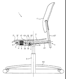
A critical parts, the office swivel chair 1 shown in Figure 1 as first
exemplary embodiment has a seating platform 2, a seat carrier 3, a rest
carrier 4
with a backrest 4' and a central chair column 5 with a foot cross 50 at its
lower end.
The seating platform 2 is a plate that is stable in and of itself and that can
be
provided with a cushion (not shown here) at its upper side. At its underside,
the
seating platform 2 is connected to two front bearing supports 21 and two back
bearing supports 22. The bearing supports 21, 22 of each support pair are
arranged
following one another in the side view shown in Figure 1, so that respectively
only
one of the bearing supports 21, 22 is visible. The front bearing supports 21
are
arranged close to the front edge of the seating platform 2 and each
respectively have
an oblong hole 21' through which a first bearing pin 31 proceeds horizontally
and
transversely. This first bearing pin 31 is rigidly connected to the seat
carrier 3,
which is in turn rigidly connected to the upper end of the central chair
column 5
by means of a chair column receptacle 30.
The back, second bearing supports 22 likewise have a respective oblong hole
22' through which a second bearing pin 32 proceeds. This second bearing pin 32
is
9
CA 02313565 2000-07-OS
rigidly connected to the seat carrier 3 and proceeds parallel to the first
bearing pin
31. The oblong hole 22' in the second bearing supports 22 thereby proceeds on
a
radius around the first, front bearing pin 31; the oblong hole 21' in the
front
bearing supports 21 proceeds on a radius around the second bearing pin 32. In
this
way, movement of the seating platform 2 is possible in vertical direction
relative to
the seat carrier 3, whereby this vertical movement can ensue both
approximately
on a straight line down as well as in the form of pivots around the first,
front
bearing pin 31 or around the second, back bearing pin 32.
In the illustrated exemplary embodiment, the rest carrier 4 carrying the
backrest 4' is formed by two rest carrier parts 40, 40'. The rest carrier part
40
proceeds under the seating platform 2; at its back end, this is connected to
the
second rest carrier part 40' in the form of a plug-type connection that
enables a
height adjustment of the second rest carrier part 40' and of the backrest 4'
secured
thereto.
The first rest carrier part 40 proceeding under the seating platform 2 is
pivotably seated with a bore 43 and a bearing pin 33, which is likewise
rigidly
connected to the seat carrier 3. The first rest carrier part 40 also comprises
an
extension 41 directed forward via the bearing pin 33 that proceeds parallel to
the
two other bearing pins 31 and 32.
Finally, the chair 1 also comprises a compression spring arrangement that is
formed here by two coil compression springs 6. The springs 6 are arranged
behind
one another in the side view, so that only one spring 6 is visible in Figure
1. The
coil compression spring 6 has its upper end supported at the underside of the
seating platform 2, namely in a region between the front bearing support 21
and the
back bearing supports 22. The coil compression spring 6 has its lower end
supported at the forwardly directed extension 41 of the first rest carrier
part 40, as a
result whereof the coil compression spring exerts an upwardly directed pre-
stressing
force, on the one hand, on the seating platform 2 and, on the other hand,
exerts a
CA 02313565 2004-12-O1
forwardly directed pre-stressing force on the backrest 4' via the first and
the second rest
carrier part 40, 40'.
The chair 1 is shown in a non-loaded condition in Figure 1 wherein no forces
are exerted on the seating platform 2 and on the backrest 4' by a user of the
chair 1.
The swivel position of the rest carrier 4 in this position is limited by a
detent that is
formed by an oblong hole 42 in the first rest carrier part 40. The second
bearing pin
32 proceeds through this oblong hole 42, whereby the bearing pin 32 lies
against the
lower end of the oblong hole 42 here.
When the chair 1 is loaded by a user, the seating platform 2 moves down to a
greater or lesser extent dependent on the body weight of the user. When the
seating
platform 2 is loaded by a heavier user, the spring arrangement 6 is more
greatly
compressed and is thereby lent higher tension. As a result thereof, the spring
arrangement 6 exerts a greater force on the extension 41 of the first rest
carrier part
40, which necessarily leads via lever action to the fact that the backrest 4'
is lent a
greater pre-stressing force toward the front, i.e. supports the user's back
with a
higher force. Given a lighter weight user of the chair 1, the seating panel 2
is pressed
down correspondingly less, as a result whereof the spring arrangement is also
tensed
less and as a result whereof the backrest 4' then also experience a lower pre-
stressing
force. The pre-stressing force or supporting force of the backrest thus
automatically
adapts to users differing in weight.
The chair 1 also offers a synchronous mechanism that allows the position of
the seating platform 2 and backrest 4' to be varied coupled to one another.
When a
user leans back on the chair 1, the seating platform 2 is lowered at the back,
whereby
the backrest 4' is simultaneously pivoted toward the back via the lever
effects that
thereby occur.
As is standard and known in and of itself, the backrest 4' can be additionally
seated at the second rest carrier part 40' pivotable around a horizontally
transversely
proceeding axis, which enables a more improved adaptation of the backrest 4'
to
various users of the chair 1. The chair column 5 is likewise a known
11
CA 02313565 2000-07-OS
and standard design and is preferably height-adjustable as well as spring-
mounted,
so that, overall, the chair 1 offers versatile possibilities of adapting to
different
users, whereby the setting of the pre-stressing force of the backrest 4'
advantageously ensues automatically dependent on the body weight of the user
of
the chair 1.
The bottom view of the chair 1 of Figure 1 shown in Figure 2 of the
drawing illustrates the symmetrical arrangement of the mechanism of the chair
1 at
both sides of the longitudinal center axis 10 of the chair. The seat carrier 3
lies in
the middle, this having the chair column receptacle 30 at its back end (the
right end
in Figure 2) for connection to the chair column 5 (not visible here). The
three
bearing pins 31, 32, 33 that proceed parallel to one another in transverse
direction
of the chair 1 under the seating platform 2 thereof are secured to the seat
carrier 3
transverse thereto. The ends of the bearing pins 31 and 32 lie in the front
and back
bearing supports 21, 22 and proceed through the oblong holes 21', 22'
described in
Figure 1 that are provided therein.
Figure 2 also shows that the first rest carrier part 40 is implemented
bipartite with two parallel sections proceeding parallel to the longitudinal
center
axis 10. The two sections of the first rest carrier part 40 are pivotably
seated at the
third bearing pin 33; the extensions 41 of the two sections of the first rest
carrier
part 40 lie in front of the third bearing pin, i.e. to the left thereof in
Figure 2. The
two coil compression springs 6 have their lower end, which faces toward the
observer here, supported on these extensions 41. The upper ends of the coil
compression springs 6 facing away from the observer are supported at.the
underside
of the seating platform 2 facing toward the observer.
It can be seen at the far right in Figure 2 that the second rest carrier part
40'
(not shown) can be connected here to the backrest 4' by being plugged to the
two
sections of the first rest carrier part 40.
Overall, Figure 2 illustrates the extremely compact structure of the
mechanism of the chair 1, as a result whereof a simple manufacturability and a
12
CA 02313565 2000-07-OS
compact structure derive. The various swivelling axes 71, 72, 73 required for
the
movements of seating platform 2 and rest carrier 4 with the backrest 4' are
formed
by the bearing pins 31, 32, 33, whereby this design is both stable as well as
low in
wear.
Figure 3 of the drawing shows a conference or consultation chair 1 as second
exemplary embodiment that comprises four chair legs 5' instead of the central
chair
column, whereby only the respective chair leg facing toward the viewer can be
seen
in the side view shown in Figure 3.
This embodiment of the chair 1 also comprises an inherently stable seating
platform 2 with a cushion 20, whereby the front and the back bearing supports
21,
22 with their oblong holes 21', 22' are again present here at the underside of
the
seating platform 2. The chair legs 5' are rigidly connected to one another via
the
seating platform 3. The three bearing pins 31, 32, 33 are also present here,
these
being in turn rigidly connected to the seat carrier 3.
The rest carrier 4 is implemented continuous here and again carries the
backrest 4' at its upper part 40'. That part 40 of the rest carrier 4 lying
under the
seating p~atform 2 is seated at the seat carrier 3 pivotable around the
bearing pin 33.
Here, too, the second, back bearing pin 32 proceeds through an oblong hole 42
in
the rest carrier part 40 in order to limit its swivel path.
Here, too, the rest carrier 4 comprises an extension 41 that proceeds toward
the front via the swivelling axis 33. The compression spring arrangement 6 has
its
lower end supported on the extension 41, whereby the upper end thereof also
lies
against the underside of the seating platform 2 here.
With respect to the movements of seating platform 2 and rest carrier 4 with
backrest 4', the chair 1 according to Figure 3 behaves like the chair 1
according to
Figure 1 and 2; here, too, an automatic adaptation of the pre-stressing force
of the
backrest 4' to the body weight of the user of the chair 1 thus ensues.
Moreover, the
synchronous mechanism for the coupled swivelling of seating platform 2 and
rest
carrier 4 with backrest 4' is also assured given the chair according to Figure
3. The
13
CA 02313565 2000-07-OS
chair 1 according to Figure 3 does not have an overall height adjustment as
possible
as a result of the chair column S given the chair 1 according to Figure 1. A
separate
height adjustment of the backrest 4' is also not provided given the chair 1
according
to Figure 3. Since the individual parts of the chair 1 according to Figure 3
can be
simplified as a result thereof, the chair 1 of this embodiment can be
especially cost-
beneficially manufactured. At the same time, however, it offers the user great
comfort due to the synchronous mechanism and due to the automatic adaptation
of
the pre-stressing force of the backrest 4' dependent on the body weight of the
respective user. Since, moreover, the entire mechanism given the chair 1
according
to Figure 3 is very compact under the seating platform 2, this chair 1 can
also be
stacked for storage and transport purposes, as known from traditional, rigid
chairs,
as a result whereof an extremely space-saving arrangement derives.
The chair 1 shown in Figure 4 as third exemplary embodiment is
implemented as office swivel chair and its critical parts are a seating
platform 2, a
seat carrier 3, a rest carrier 4 for a backrest (not shown here) arranged
farther up, a
central chair column 5 with a foot cross (likewise not shown here) at its
lower end,
and a spring arrangement 6 between seating platform 2 and rest carrier 4.
The seating platform 2 is an inherently stable plate that can be provided
with a cushion (not shown here) at its upper side. At its underside, the
seating
platform 2 is connected to a support component 23 having a respective left and
right, downwardly directed cheek 23'. Close to the front edge of the seating
platform 2 lying at the left in the drawing, the cheeks 23' of the support
component
23 respectively comprise an oblong hole 21' through which a first bearing pin
31
proceeds horizontally and transversely. This first bearing pin 31 is rigidly
connected to the seat carrier 3 that is in turn rigidly connected to the upper
end of
the central chair column 5 by means of a chair column receptacle 30 lying
centrally
under the seating platform 2.
Farther toward the back, here roughly centrally under the seating platform
2, the cheeks 23' of the support component 23 as well as the rest carrier 4
comprise
14
CA 02313565 2000-07-OS
further oblong holes 22', 42 through which a second bearing pin 32 proceeds.
This
second bearing pin 32 is also rigidly connected to the seat carrier 3 and
proceeds
parallel to the first bearing pin 31 offset down by about a pin thickness. The
oblong hole 22' thereby respectively proceeds on a radius around the first
bearing
pin 31 in an essentially vertical direction, and the oblong hole 21' proceeds
on a
radius around the second bearing pin. In this way, a movement of the seating
platform 2 is possible in vertical direction relative to the seat carrier 3,
whereby this
vertical motion can ensue both approximately on a straight line vertically as
well as
in the form of swivels around the first, front bearing pin 31 or around the
second,
back bearing pin 32.
In the illustrated exemplary embodiment, the rest carrier 4 is formed by two
rest carrier parts 40, 40'. The rest carrier part 40 proceeds under the
seating
platform 2; at its back end, this is connected to the second rest carrier part
40' be a
plug-type connection that enables an adjustment of the second rest carrier
part 40'
with the backrest secured thereto.
The first rest carrier part 40 proceeding under the seating platform 2 is
pivotably seated at the seat carrier 3 by a third bearing pin 33 that is
likewise rigidly
connected to the seat carrier 3. Further, the first rest carrier part 40
comprises an
extension 41 directed forward via the bearing pin 33 that proceeds parallel to
the
two other bearing pins 31, 32. Moreover, the support component 23 and the rest
carrier part 40 are connected to one another in articulated fashion here via a
dog 24
in the form of a short lever in order to effect the synchronism of the swivel
of
seating platform 2 and backrest.
Finally, the chair 1 also comprises the spring arrangement 6 that is formed
by two torsion springs 60 here. The torsion springs 60 are arranged behind one
another in the side view, so that only the one torsion spring 60 is visible in
Figure
4. The torsion spring 60 has a coiled spring member 61 that proceeds around
the
bearing pin 33 forming the third swivelling axis 73 and is held thereon with a
holder that has not been numbered. A respective upper spring leg 62 and a
lower
," CA 02313565 2005-02-16
spring leg 64 proceed tangentially from the spring member 61 toward the front
roughly parallel to one another. Close to its free end, the first, upper
spring leg 62 of
the torsion spring 60 is supported at the underside of the seating platform 2,
namely
in a region between the bearing pins 31 and 33. To reduce wear and noise, a
pressure
member 63 is provided here as part of the support component 23, this being
attached
to the underside of the seating platform 2. The spring legs 62 lie against the
pressure
member 63. The torsion spring 60 has its second, lower spring leg 64 supported
at the
forwardly directed extension 41 of the first rest carrier part 40, as a result
whereof, on
the one hand, the torsion spring 60 exerts an upwardly directed pre-stressing
force
onto the seating platform 2 and, on the other hand, exerts a forwardly
directed pre-
stressing force on the backrest via the first and the second rest carrier part
40, 40'.
Figure 4 shows the chair 1 in a non-loaded condition wherein no forces are
exerted on the seating platform 2 and on the backrest and its rest carrier
parts 40, 40'
by a user of the chair 1. The swivelled position of the rest carrier 4 is
limited in this
position by a detente that is formed by the oblong hole 42 in the first rest
carrier part
40. The second bearing pin 32 proceeds through this oblong hole 42, whereby
the
bearing pin 32 lies against the lower end of the oblong hole 42 here.
When the chair 1 is loaded by a user, the seating platform 2 moves down to a
greater or lesser extent dependent on the body weight of the user. When the
seating
platform 2 is loaded by a heavier user, the spring legs 62, 64 of the torsion
springs to
are more greatly compressed, and the torsion springs 60 are thereby lent a
higher
tension. As a result thereof, the torsion springs 60 also exert a greater
force onto the
extension 41 of the first rest carrier part 40, which, via the lever effect,
necessarily
leads thereto that the backrest is lent a higher pre-stressing force toward
the front, i.e.
supports the user's back with a higher force. Given a lighter weight user of
the chair
1, the seating platform 2 is pressed down correspondingly less, as a result
whereof the
springs 60 are also tensed to a lesser extent, and as a result whereof the
lbackrest also
experiences less of a pre-stressing force. The pre-stressing
16
CA 02313565 2000-07-OS
or supporting force of the backrest thus automatically adapts to users
differing in
weight.
The chair 1 also offers a synchronous mechanism that sees to it that, when
the chair 1 is used, the positions of seating platform 2 and backrest 4'
change
coupled with one another. When a user leans back on the chair 1, the seating
platform 2is more highly loaded at the back and lowers there, whereby, via the
dog
24, the backrest is simultaneously swivelled toward the back in a fixed swivel
relationship via the lever effects that thereby occur. When the synchronous
mechanism is not desired, this can be eliminated simply by omitting the dog
24.
As is known in and of itself and standard, the backrest can be additionally
seated at the second rest carrier part 40' pivotable around a horizontally
transversely proceeding axis, which enables a further improved adaptation of
the
backrest to various users of the chair 1. The chair column 5 likewise has a
known
and standard design and is preferably height-adjustable as well as spring
mounted,
so that, overall, the chair 1 offers versatile adaptation possibilities to
different users.
The setting of the pre-stressing force of the backrest thereby advantageously
ensues
automatically dependent on the body weight of the user of the chair 1, so that
manual adjustments are not necessary therefor.
The bottom view of the chair of Figure 4 shown in Figure 5 of the drawing
illustrates the symmetrical arrangement of the mechanism of the chair 1 at
both
sides of the longitudinal center axis 10 of the chair. The seat carrier 3,
which
comprises the chair column receptacle 30 for connection to the chair column 5
(not
visible here) at its back, right-hand end in Figure 5, lies in the middle. The
three
bearing pins 31, 32, 33 that proceed parallel to one another in transverse
direction
of the chair 1 under the seating platform 2 thereof (which is not shown here)
are
secured to the seat carrier 3 transverse thereto. The ends of the bearing pins
31 and
32 lie in the two lateral cheeks 23' of the support component 23 and proceed
through the oblong holes 21', 22' provided therein that are described in
Figure 4.
17
CA 02313565 2000-07-OS
Figure 5 also shows that the first back carrier part 40 is implemented of one
piece as a flat strip with two parallel, lateral bevels that proceed parallel
to the
longitudinal center axis 10. The first rest carrier part 40 is pivotably
seated at the
third bearing pin 33; the extension 41 of the first rest carrier part 40 lies
in front of
the third bearing pin, i.e. to the left thereof in Figure 5. The two torsion
springs 60
have their spring legs 64 supported on this extension 41. The torsion springs
60
have their spring legs 62 supported at the underside (facing toward the
viewer) of
the seating platform 2 (not shown) that lies in the background here.
It can be seen at the far right in Figure S that the second rest carrier part
40'
(not shown here) can be connected to the backrest by plugging to the first
rest
carrier part 40.
Overall, Figure 5 illustrates the extremely compact structure of the
mechanism of the chair 1, as a result whereof a simple manufacturability and a
"light" appearance pf the chair 1 derive. The three swivelling axes 71, 72, 73
required for the movements of seating platform 2 and rest carrier'4 with the
backrest are formed by the bearing pins 31, 32, 33, whereby this design is
both
stable as well as low in wear.
Figures 6 and 7 of the drawing show a further office swivel chair 1 as fourth
exemplary embodiment that likewise comprises a central chair column 5, whereby
only the upper end of the chair column that is connected to that end of the
seat
carrier 3 lying centrally under the seating platform 2 can be seen in the
partial side
view shown in Figure 6.
This embodiment of the chair 1 also comprises an inherently stable seating
platform 2, whereby front bearing supports 21 each having a respective,
vertical
oblong hole and back bearing supports 22 are present at the underside thereof
respectively separated from one another. Differing from the first exemplary
embodiment, however, only two bearing pins 32, 33 are present here, the pin 33
thereof being rigidly connected to the seat carrier 3, whereas the pin 32 is
fixed in
the bearing support 22.
18
CA 02313565 2000-07-OS
The rest carrier 4 is also implemented bipartite here and carries the backrest
(not shown) at its upper part 40'. That part 40 of the rest carrier 4 lying
under the
seating platform 2 is seated at the seat carrier 3 pivotable around the
swivelling axis
73 by means of the bearing pin 33. Here, too, the second, back bearing pin 32
proceeds through an oblong hole 42 in the rest carrier part 40, whereby the
oblong
hole 42 here proceeds through the rest carrier part 40 in longitudinal
direction
thereof in order to enable the force-free swivelling thereof.
Here, too, the rest carrier 4 comprises an extension 41 of one piece with the
rest carrier part 40 that proceeds toward the front via the swivelling axis
73.
A torsion bar spring 60' is installed here as spring element 6. This spring
60'
has two spring sections 61' stressed for torsion that proceed in transverse
chair
direction through the oblong holes 21' and simultaneously serve as first
swivelling
axis 71. At the outside left and right, a respective spring lever 62' extends
toward
the back from the spring section 61' and lies against a respective detent 26
that is
respectively attached to the underside of the seating platform 2. Two further
spring
levers 64' that likewise proceed in the direction toward the back and that are
supported on the extension 41 of the rest carrier part 40 in a region
connecting
their free ends lie in the region between the spring sections 61'. The spring
60'
shown here is implemented as symmetrical double spring and is manufactured of
one piece from a correspondingly bent spring steel bar. The torsion bar spring
60'
is pre-stressed such that its spring levers 62', 64' exert the desired,
upwardly
directed force onto the seating platform 2 and the desired, downwardly
directed
force onto the extension 41, as indicated by the arrows at the spring levers
62', 64'.
With respect to the movements of seating platform 2 and rest carrier 4 with
backrest, the chair 1 according to Figures 6 and 7 behaves like the chair 1
according
to Figure 4 and 5; here, too, an automatic adaptation of the pre-stressing
force of
the backrest to the body weight of the user of the chair 1 thus ensues.
Moreover,
the synchronous mechanism for coupled swivelling of seating platform 2 and
rest
carrier 4 with backrest is also assured given the chair 1 according to Figures
6 and 7.
19
CA 02313565 2000-07-OS
The chair 1 according to Figures 6 and 7 can also have an overall height
adjustment as possible with the chair column 5 given the chair 1 according to
Figures 4 and 5. A separate height adjustment of the backrest can also be
provided
given the chair 1 according to Figures 6 and 7.
It is especially advantageous that the entire mechanism given the chair 1
according to Figures 6 and 7 is very compact under the seating platform 2 and
occupies only little structural height and that only few discrete parts are
required.