Language selection

Search

Patent 2313591 Summary

Third-party information liability

Some of the information on this Web page has been provided by external sources. The Government of Canada is not responsible for the accuracy, reliability or currency of the information supplied by external sources. Users wishing to rely upon this information should consult directly with the source of the information. Content provided by external sources is not subject to official languages, privacy and accessibility requirements.

Claims and Abstract availability

Any discrepancies in the text and image of the Claims and Abstract are due to differing posting times. Text of the Claims and Abstract are posted:

  • At the time the application is open to public inspection;
  • At the time of issue of the patent (grant).
(12) Patent: (11) CA 2313591
(54) English Title: WHEEL SUPPORTER AND SHAFT FOR A GOLF CART
(54) French Title: SUPPORT DE ROUES ET ARBRE DE CHARIOT DE GOLF
Status: Expired
Bibliographic Data
(51) International Patent Classification (IPC):
  • B60B 35/04 (2006.01)
  • A63B 55/60 (2015.01)
  • B60B 37/10 (2006.01)
  • B62B 1/04 (2006.01)
(72) Inventors :
  • LIAO, GORDON (Taiwan, Province of China)
(73) Owners :
  • UNIQUE PRODUCT & DESIGN CO., LTD. (Taiwan, Province of China)
(71) Applicants :
  • UNIQUE PRODUCT & DESIGN CO., LTD. (Taiwan, Province of China)
(74) Agent: ROBIC
(74) Associate agent:
(45) Issued: 2007-08-21
(22) Filed Date: 2000-07-05
(41) Open to Public Inspection: 2002-01-05
Examination requested: 2003-07-30
Availability of licence: N/A
(25) Language of filing: English

Patent Cooperation Treaty (PCT): No

(30) Application Priority Data: None

Abstracts

English Abstract

A wheel supporter and shaft for a golf cart includes a wheel shaft having an end portion protruding out of a wheel. The protruding end portion is formed with two opposite recesses respectively provided with a curved projection. The wheel supporter has a shaft hole for the wheel shaft to fit therein, and an eccentric push member is pivotally connected under a bottom wall of the shaft hole. The eccentric push member has two round projections to protrude in the shaft hole to engage a space between each recess and each curved projection so that the wheel supporter may be locked with the wheel shaft in a stabilized condition with easy handling.


French Abstract

Support et arbre de roue pour chariot de golf, dont une extrémité de l'arbre de roue dépasse la roue. L'extrémité qui dépasse est formée de deux cavités opposées respectivement fournies avec une saillie courbée. Le support est doté d'un trou pour intégrer la roue, et un élément de pression excentrique est raccordé de manière pivotante au fond du trou d'arbre. L'élément de pression excentrique a deux saillies rondes qui peuvent être insérées dans le trou d'arbre pour occuper l'espace entre chaque cavité et chaque saillie courbée de sorte que le support de roue puisse être verrouillé avec l'arbre de roue en état stable et être manipulé facilement.

Claims

Note: Claims are shown in the official language in which they were submitted.


WHAT IS CLAIMED IS:

1. A wheel supporter and shaft for a golf cart comprising:
a wheel supporter and a wheel shaft, said wheel shaft having one end
portion protruding out of a wheel, said protruding end portion is formed with
two
recesses therein, each said recess having a curved projection, said wheel
supporter having a shaft hole to receive said wheel shaft, an eccentric push
member is located under a bottom wall of said shaft hole, said eccentric push
member having two round projections that protruded in said shaft hole, each
said round projection engages a space between a respective one of said
recesses and a respective one of said curved projections so that said wheel
supporter is locked with said wheel shaft, the eccentric push member being
swingingly pushable down to force the two round projections into a
disengagement from the recesses and the curved projections while the wheel
shaft is pulled out of the shaft hole, the wheel supporter being then
disengaged
from the wheel shaft.

2. The wheel supporter and shaft for a golf cart as claimed in claim 1,
wherein said protruding end portion of said wheel shaft and said shaft hole of
said wheel supporter are both rectangular in cross section.

3. The wheel supporter and shaft for a golf cart as claimed in claim 1,
wherein said protruding end portion of said wheel shaft and said shaft hole of
said wheel supporter are both tapered from an outer end to an inner end.

4. The wheel supporter and shaft for a golf cart as claimed in claim 1,
wherein said eccentric push member has two projection ears formed in a first
end, one of the round projections extends from the inner surfaces of the
projecting ears and a curved push means is formed in a second end of said
eccentric push member.

6

Description

Note: Descriptions are shown in the official language in which they were submitted.


CA 02313591 2006-03-20

TITLE: WHEEL SUPPORTER AND SHAFT FOR A GOLF CART
BACKGROUND OF THE INVENTION

This invention relates to a wheel supporter and a shaft for a golf cart,
particularly to one having a simple structure for easy assemblage and
collapsing.

Conventional golf carts are generally made collapsible, with a wheel
supporter and shaft capable to be collapsed and assembled by a user, so as
to be easily carried with a small dimensions or stored in a car trunk after
collapsed.

Nowadays, there are two kinds of conventional wheel supporters
and shafts for a golf cart.

A first kind of conventional wheel supporter and shaft is shown in
Figs. 1 and 2, including a wheel supporter 1 consisting of a metal plate unit
11. The metal plate unit 11 has a pin 35 to pivotally connect a recover

spring 34 and a push member 3, a shaft hole 111 for a shaft 21 of a wheel 2
to insert therein. The push member 3 has a projecting pointed member 31 in
an intermediate portion, a groove 32 under the pointed member 31, and an
engage plate portion 33 formed in an upper portion. The recover spring 34

has one end hooked on the metal plate unit 11, and the other end hooked at
a middle point of the push member 3, controlling engagement and
disengagement of the groove 32 of the push member 3 and an annular
groove 211 of the shaft 21.

This conventional wheel supporter and shaft is convenient in
handling, but its structure is a little complicated for assembly or
collapsing.
The second kind of conventional wheel supporter and shaft is shown

in Figs. 3 and 4, including a wheel supporter 10, which has a rectangular
1


CA 02313591 2006-03-20

opening 14 and an insert hole 12, a coil spring 13 contained in the opening
14, and an engage block 5 elastically urged by the coil spring 13 and
normally located in the opening 14 to be able to be half pushed out of the
opening 14. The engage block 5 has a protruding hook 51 in a left

longitudinal side of an outer block portion engaging an inner wall of the
opening 14, and an L-shaped position hook 52 with a sloped surface
extending inward from the outer block portion. A wheel shaft 4 has one
end firmly connected to a wheel 20 and the other end portion 41 formed
with a distal square end 43 facing the sloped surface of the L-shaped

position hook 52 of the engage block 5 located in the wheel supporter 10,
and an intermediate groove portion 42 to engage the L-shaped position
hook 52.

In handling the second conventional wheel supporter and shaft, the
wheel shaft 4 is inserted in the insert hole 12 of the wheel supporter 10,
with the other end portion of the wheel shaft 4 engaging the L-shaped

position hook 52 of the engage block 5, finishing assemblage of the wheel
supporter 10 with the wheel shaft 4. On the contrary, if the wheel shaft 4 is
to be pulled out of the wheel supporter 10, the push block 5 is pushed up (in
Fig. 4, or inward) to compress the coil spring 13, forcing the L-shaped

position hook 52 disengage from the other end portion 41 of the wheel shaft
4 to free the wheel shaft 4 from the wheel supporter 10.

However, the second conventional wheel supporter and shaft is also
handy to handle, but its structure is also complicated for assembly and
collapsing.

SUMMARY OF THE INVENTION

The purpose of the invention is to offer a wheel supporter and shaft
for a golf cart, having a simpler structure than the conventional ones for
2


CA 02313591 2006-03-20
easy assemblage and collapsing.
According to the present invention, there is provided a wheel supporter
and shaft for a golf cart comprising:
a wheel supporter and a wheel shaft, said wheel shaft having one end
portion protruding out of a wheel, said protruding end portion is formed with
two
recesses therein, each said recess having a curved projection, said wheel
supporter having a shaft hole to receive said wheel shaft, an eccentric push
member is located under a bottom wall of said shaft hole, said eccentric push
member having two round projections that protruded in said shaft hole, each
said round projection engages a space between a respective one of said
recesses and a respective one of said curved projections so that said wheel
supporter is locked with said wheel shaft, the eccentric push member being
swingingly pushable down to force the two round projections into a
disengagement from the recesses and the curved projections while the wheel
shaft is pulled out of the shaft hole, the wheel supporter being then
disengaged
from the wheel shaft.

BRIEF DESCRIPTION OF DRAWINGS

This invention will be better understood by referring to the
accompanying drawings, wherein

Figure 1 is a perspective view of a first conventional wheel
supporter and shaft for a golf cart;

Figure 2 is an exploded perspective view of the first conventional
wheel supporter and shaft for a golf cart;

Figure 3 is an exploded perspective view of a second conventional
wheel supporter and shaft for a golf cart;

Figure 4 is a side cross-sectional view of the second conventional
wheel supporter and shaft for a golf cart, showing the wheel shaft
disengaged from the wheel supporter;

Figure 5 is a side cross-sectional view of the second conventional
3


CA 02313591 2006-03-20

wheel supporter and shaft for a golf cart, showing the wheel shaft engaged
with the wheel supporter;

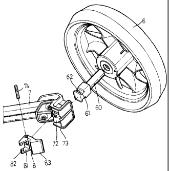
Figure 6 is an exploded perspective view of a wheel supporter and
shaft for a golf cart in the present invention;

Figiu-e 7 is a cross-sectional view of the wheel supporter disengaged
from the wheel shaft in the present invention;

Figure 8 is a perspective view of the wheel supporter engaged with
the wheel shaft in the present invention;

Figure 9 is a cross-sectional view of the wheel supporter engaged
with the wheel shaft in the present invention; and,

Figure 10 is a cross-sectional view of A-A line in Fig. 9.
3a


CA 02313591 2006-03-20

DETAILED DESCRIPTION OF THE PREFERRED EMBODIMENT
A preferred embodiment of a wheel supporter and shaft for a golf
cart in the present invention, as shown in Figs. 6 and 7, includes a wheel
shaft60 having a round end to fix firnily with a wheel 6 and the other end

protruding out of a wheel 6 and shaped rectangular and having two opposite
recesses 61 of smaller size than the rest portion and a curved projection 62
formed in each recess 61. A wheel supporter 7 has a rectangular shaft hole
71 formed in a lower end for the wheel shaft 60 to fit therein, a pivotal base
72 formed in a bottom wall defining the shaft hole 71, a groove 73 for-med

respectively at two sides of the pivotal base 72 for pivotally connecting an
eccentric push member 8 with a pin shaft 74. The eccentric push member 8
has two projecting ears 81 formed in an upper portion, and a round
projection 82 respectively formed on an inner side of each ear 81 to pass
through the grooves 73 and extend in the shaft hole 71, and a cuived push
means 83 formed in the other end portion.

In assembling the wheel supporter 7 with the wheel shaft 60, firstly
insert the wheel shaft 60 together with the wheel 6 in the shaft hole 71 of
the wheel supporter 7, with the two opposite recesses 61 just facing the
grooves 73. Then pull backward the eccentric push member 8 as shown

with an arrow head in Fig. 7, forcing the two round projections 82 extend in
the recesses 61, slide over the curved projections 62 and engage the space
between each projection 62 and the each recess 61, securing the wheel
supporter 7 with the wheel shaft 60, as shown in Figs. 8 and 9.

On the contrary, if the wheel supporter 7 is to be disengaged from
the wheel shaft 60, only push swingingly down the eccentric push member
8, forcing the two round projections 82 disengage from the recesses 61 and
the projections 62, with the wheel shaft 60 pulled out of the shaft hole 71,
~


CA 02313591 2000-11-20
as shown in Figs. 7.

It has to be noted that the protrucling end portion of the wheel shaft
60 protruding out the wheel 6 may gradually enlarged to the rear portion in
corresponding to the hole 71 also gradually enlarged to the rear portion so

that the wheel shaft 60 may easily fit in the shaft hole 71, as shown in Fig.
7.

As can be understood from the aforesaid description, the wheel
supporter 7 may be disengaged from the wheel shaft 60 only by pulling or
pushing the eccentric push member 8, which is a very simple structure for
handling.

While the preferred embodiment of the invention has been described
above, it will be recognized and understood that various modifications may
be made therein and the appended clairns are intended to cover all such
modifications which may fall within the spirit and scope of the invention.

20
5

Representative Drawing
A single figure which represents the drawing illustrating the invention.
Administrative Status

For a clearer understanding of the status of the application/patent presented on this page, the site Disclaimer , as well as the definitions for Patent , Administrative Status , Maintenance Fee  and Payment History  should be consulted.

Administrative Status

Title Date
Forecasted Issue Date 2007-08-21
(22) Filed 2000-07-05
(41) Open to Public Inspection 2002-01-05
Examination Requested 2003-07-30
(45) Issued 2007-08-21
Expired 2020-07-06

Abandonment History

There is no abandonment history.

Payment History

Fee Type Anniversary Year Due Date Amount Paid Paid Date
Registration of a document - section 124 $100.00 2000-07-05
Application Fee $150.00 2000-07-05
Maintenance Fee - Application - New Act 2 2002-07-05 $50.00 2002-07-03
Maintenance Fee - Application - New Act 3 2003-07-07 $50.00 2003-07-02
Request for Examination $200.00 2003-07-30
Maintenance Fee - Application - New Act 4 2004-07-05 $50.00 2004-07-02
Maintenance Fee - Application - New Act 5 2005-07-05 $100.00 2005-06-07
Maintenance Fee - Application - New Act 6 2006-07-05 $100.00 2006-06-08
Final Fee $150.00 2007-04-13
Maintenance Fee - Application - New Act 7 2007-07-05 $100.00 2007-05-29
Maintenance Fee - Patent - New Act 8 2008-07-07 $100.00 2008-06-05
Maintenance Fee - Patent - New Act 9 2009-07-06 $100.00 2009-06-04
Maintenance Fee - Patent - New Act 10 2010-07-05 $125.00 2010-05-20
Maintenance Fee - Patent - New Act 11 2011-07-05 $125.00 2011-06-08
Maintenance Fee - Patent - New Act 12 2012-07-05 $125.00 2012-06-12
Maintenance Fee - Patent - New Act 13 2013-07-05 $125.00 2013-06-10
Maintenance Fee - Patent - New Act 14 2014-07-07 $125.00 2014-05-29
Maintenance Fee - Patent - New Act 15 2015-07-06 $225.00 2015-06-03
Maintenance Fee - Patent - New Act 16 2016-07-05 $225.00 2016-06-16
Maintenance Fee - Patent - New Act 17 2017-07-05 $225.00 2017-05-26
Maintenance Fee - Patent - New Act 18 2018-07-05 $225.00 2018-06-12
Maintenance Fee - Patent - New Act 19 2019-07-05 $225.00 2019-05-27
Owners on Record

Note: Records showing the ownership history in alphabetical order.

Current Owners on Record
UNIQUE PRODUCT & DESIGN CO., LTD.
Past Owners on Record
LIAO, GORDON
Past Owners that do not appear in the "Owners on Record" listing will appear in other documentation within the application.
Documents

To view selected files, please enter reCAPTCHA code :


To view images, click a link in the Document Description column. To download the documents, select one or more checkboxes in the first column and then click the "Download Selected in PDF format (Zip Archive)" or the "Download Selected as Single PDF" button.

List of published and non-published patent-specific documents on the CPD .

If you have any difficulty accessing content, you can call the Client Service Centre at 1-866-997-1936 or send them an e-mail at CIPO Client Service Centre.


Document
Description 
Date
(yyyy-mm-dd) 
Number of pages   Size of Image (KB) 
Cover Page 2002-01-02 1 40
Representative Drawing 2001-12-11 1 13
Drawings 2000-11-20 10 163
Abstract 2000-11-20 1 19
Description 2000-11-20 5 197
Claims 2000-11-20 1 39
Abstract 2000-07-05 1 22
Description 2000-07-05 6 228
Claims 2000-07-05 2 48
Drawings 2000-07-05 10 171
Description 2006-03-20 6 211
Claims 2006-03-20 1 42
Drawings 2006-03-20 10 158
Representative Drawing 2007-07-27 1 15
Cover Page 2007-07-27 1 42
Correspondence 2000-08-14 1 17
Assignment 2000-07-05 5 161
Correspondence 2000-11-20 10 319
Fees 2003-07-02 1 27
Prosecution-Amendment 2003-07-30 1 28
Prosecution-Amendment 2000-11-20 13 224
Fees 2002-07-03 1 33
Fees 2004-07-02 1 26
Fees 2005-06-07 1 27
Prosecution-Amendment 2005-09-21 2 58
Prosecution-Amendment 2006-03-20 14 366
Fees 2006-06-08 1 32
Correspondence 2007-04-13 1 42
Fees 2007-05-29 1 43
Fees 2009-06-04 1 36
Fees 2008-06-05 1 50
Fees 2010-05-20 1 36
Correspondence 2010-05-20 1 36
Correspondence 2010-08-10 1 46
Fees 2011-06-08 1 36
Fees 2012-06-12 1 41
Fees 2013-06-10 1 40
Fees 2014-05-29 1 39
Maintenance Fee Payment 2015-06-03 1 40