Note: Descriptions are shown in the official language in which they were submitted.
CA 02313685 2000-07-10
TITLE: GRINDING APPARATUS
BACKGROUND OF THE INVENTION
The present invention relates to improvements in
apparatus for grinding the hard metal inserts or working
tips of drill bits (percussive or rotary), tunnel boring
machine cutters (TBM) and raised bore machine cutters (RBM)
and more specifically, but not exclusively, for grinding
the tungsten carbide cutting teeth or buttons of a drill
bit or cutter.
In drilling operations the cutting teeth
(buttons) on the drill bits or cutters become flattened
(worn) after continued use. Regular maintenance of the
drill bit or cutter by regrinding (sharpening) the buttons
to restore them to substantially their original profile
enhances the bit/cutter life, speeds up drilling and
reduces drilling costs. Regrinding should be undertaken
when the wear of the buttons is optimally one third to a
maximum of one-half the button diameter.
Different manual and semi-automatic grinding
machines are known for grinding button bits/cutters (see
for example U.S. Patent No. 5,193,312; 5,070,654). In a
conventional type of machine a grinding cup having the
desired profile is rotated at high speed to grind the
carbide button and the face of the bit/cutter surrounding
the base of the button to restore the button to
substantially its original profile for effective drilling.
BRIEF DESCRIPTION OF THE DRAWINGS
In order that the invention may be more clearly
understood, the preferred embodiment thereof will now be
described in detail by way of example, with reference to
the accompanying drawings, in which:
PHOTO 1 is a front view of a grinding apparatus according
to the present invention having a box and tilting
CA 02313685 2000-07-10
2
table and grinding machine carried for vertical and
horizontal adjustment by an arm or lever system
journaled on a stand;
PHOTO 2 is a close-up view of the box and tilting table of
the grinding apparatus of PHOTO 1;
PHOTO 3 is a view of the left side of the box of PHOTO 1
showing the means of tilting the table;
PHOTO 4 is a view of the right side of the box of PHOTO
1;
PHOTO 5 is a close-up view of the top of the tilting table
of the grinding apparatus of PHOTO 1;
PHOTO 6 is a side view of the grinding machine carried for
vertical and horizontal adjustment by an arm or
lever system of PHOTO 1;
PHOTO 7 is a close-up of the grinding machine of PHOTO 1;
PHOTO 8 is a close-up of the control panel for setting
the balance pressure and feed pressure for the
grinding machine of PHOTO 7;
PHOTO 9 is a view of the back of the grinding apparatus
of PHOTO 1;
PHOTO 10 is a close up view from the front of the cylinder
for providing backpressure to the grinding
machine;
PHOTO 11 is a close up view from the rear of the cylinder
of PHOTO 10;
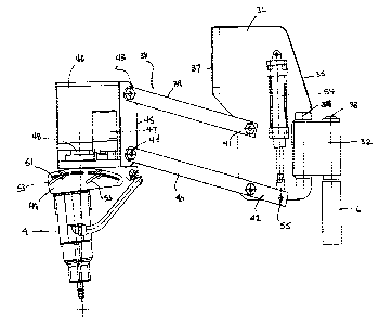
Fig. 1 is a side plan view partly in section of the
grinding machine carried for vertical and
horizontal adjustment by an arm or lever system;
and
Fig. 2 is a top plan view of the grinding machine and
arm or lever system of Fig. 1.
DETAILED DESCRIPTION OF PREFERRED EMBODIMENTS
With reference to the PHOTOS and Figs one
embodiment of a grinding apparatus according to the present
invention is generally indicated at 1. The grinding
CA 02313685 2000-07-10
3
apparatus 1 consists of a box 2 having a table 3 for
holding one or more bits to be ground. A grinding machine 4
is carried by an arm or lever system, generally indicated
at 5, journaled on a stand 6 attached to the rear of box 2.
As best seen in PHOTOS 3 and 9 a compressed air feed 7 is
provided to operate various aspects of the grinding
apparatus as discussed in detail below.
Table 3 is tiltably mounted within box 2 at pivot
points 8,9 on each side of the box 2 (see PHOTOS 3 and 4).
The table 3 is provided with one or more apertures 10 to
hold one or more bits to be ground. A bits) (not shown) is
positioned in aperture 10. The bit is held in place by
pressure plate 11 controlled by a locking cylinder 12. The
locking cylinder can be backed off slightly to rotate the
bit (to the next button to be ground) within the aperture
10 without full release of the pressure on the locking
cylinder. If the button to be ground is a gauge button, it
is mounted in the bit at an angle relative to the face of
the bit. The grinding machine 4 in order to properly
regrind a worn button must be aligned over the longitudinal
axis of the button. Accordingly to regrind the gauge
buttons, table 3 is tilted to correspond to the angle at
which the gauge buttons are mounted in the bit. The means
of tilting table 3 is best illustrated with reference to
PHOTO 3. An arced slot 13 is provided in the side of box 2.
A scale 14 is preferably provided to indicate the angle at
which the table 3 will be tilted. A stop 15 is positioned
within the slot 13 at the desired angle and locked in place
by lever 16. Once set for a particular bit type, the angle
is fixed and doesn't have to be reset for each bit or
button to be reground. A cylinder 17 is provided on the
side of the box 2 and the end 18 of the cylinder rod 19 is
connected to the side 20 of table 3 at point 21. When air
is fed to cylinder 17, extension of the rod 19 will tilt
table 3 until further extension is prevented by stop 15. As
shown in PHOTO 2, controls, generally indicated at 22, for
tilting the table and locking the bits) in place are
CA 02313685 2000-07-10
4
provided at the front of the box. One switch 23 controls
the cylinder 17 for tilting the table 3 and a second switch
24 controls the locking cylinder 12 and pressure plate 11.
Flow controls are provided to regulate the speed of
movement of the table and the pressure plate. The tilting
means can be mounted on either side of the box so that two
boxes may be mounted side by side.
Large down the hole bits to be reground typically
have a relatively long shaft that fits through aperture 10.
In order to regrind smaller bits a floor plate 25 that can
be pivoted (slid) in and out of position under aperture 10
is provided. Knob 26 and slot 27 in table 3 control the
location of the floor plate 25. Adapters for holding
multiple small sized bits can be inserted into aperture 10.
In PHOTO 5 two different types of adapters are shown. In
the left aperture a W-shaped adapter 28 is provided. In the
right aperture an air-actuated adapter 29 is illustrated.
The adapter 29 has a pair of adjustable outer plates to
accommodate different sizes of bits and air actuated
locking plates. Use of the adapters eliminates repetitive
set up time for the operator.
A splash guard 30 is provided at the front of the
box 2 that can be raised and lowered along a slot 31 along
each side of the front edge of box 2. A counter balancing
spring assists in the ease of operation of splashguard 30.
The splashguard 30 can be set and retained at different
heights as desired.
The arm system 5 for carrying and positioning
grinding machine 4 as noted previously is journaled onto
stand 6 . With reference to PHOTOS 6 to 11 and Figs . 1 and
2, the arm system 5 consists a first arm section 32 having
one end 33 journaled to stand 6. The other end 34 of the
first arm section 32 is journaled to the back side 35 of a
first control box 36. The first arm section 32 controls the
horizontal location of the grinding machine relative to the
bit to be reground. To the front side 37 of control box 36
is pivotally mounted a second arm section 38. The second
CA 02313685 2000-07-10
arm section 38 consists of a pair of parallel arms 39, 40
with one end 41,42 of each arm 39,40 pivotally mounted to
the front side 37 of the first control box 36. The other
end 43,44 of each arm 39, 40 is pivotally connected to the
5 back side 45 of a second control box 46. The second arm
section 38 controls the vertical movement of the grinding
machine up and down.
Within the second control box 46, is a rotation
motor 47 and bearing arrangement 48 for providing an
orbital rotation to grinding machine 4. The grinding
machine 4 is attached to control box 46 by means of plates
49, 50. The grinding machine 4 has an electric
motor/grinding head in the embodiment shown but can also
utilize an air or hydraulic motor, etc. Each of the plates
49, 50 is provided with an acruate slot 51, 52. The angle
of attachment of the grinding machine 4 relative to control
box 46 can be adjusted by means of slots 51, 52 and locking
levers 53. By having the grinding machine/grinding head
oscillate slightly off vertical, nipple formation on the
button being reground is minimized and uneven wear on the
grinding cup avoided.
Within the first control box 36, is a cylinder 54
connected to an end 42 of the lower arm 40 of the second
arm section 38. The end 42 of lower arm 40 extends out from
the pivot point 55 at which the lower arm 40 is connected
to the first control box 36. Cylinder 54 provides a balance
pressure to the second arm section when the grinding
machine is not in use and grinding pressure/feed when in
use. The grinding balance pressure and pressure/feed can be
adjusted.
When grinding buttons the self-centering aspects
of the grinding machine tend to center the grinding machine
over the highest point on the button. On buttons where wear
is uneven, typically gauge buttons, this may result in
35. regrinding the button off center from its vertical axis. To
substantially center the grinding machine over the
longitudinal axis of the button, the first arm section 32
CA 02313685 2000-07-10
6
is provided with a cylinder 56 having one end 57 connected
to stand 6 and the other end 58 connected to the bottom 59
of the first arm section 32. The cylinder 56 provides a
side load to grinding machine 4 to help center the grinding
machine over the button. In the embodiment shown, the
cylinder 56 is automatically activated when the table is
tilted by the pilot feed from cylinder 17 through valve 60.
The side load biases the grinding machine to grind more on
the inside of the gauge buttons thereby tending to shift
the grinding machine over the true center of the button.
The suitable side load can be provided by other means such
as counter weights, etc.
In addition, variations of the same above
described principle of biased side loads or counter
balancing can also be used to allow for grinding at angles
other than vertical. Combinations of variations of the
above described principle of biased side loads or counter
balancing can be used to substantially eliminate the need
for tilting/pivoting the bit when switching between
grinding of face buttons and gauge buttons. This principle
would be ideal in cases were tilting or pivoting of the bit
is difficult due to size, weight, etc.
Having illustrated and described a preferred
embodiment of the invention and certain possible
modifications thereto, it should be apparent to those of
ordinary skill in the art that the invention permits of
further modification in arrangement and detail.
It will be appreciated that the above description
related to the preferred embodiment by way of example only.
Many variations on the invention will be obvious to those
knowledgeable in the field, and such obvious variations are
within the scope of the invention as described and claimed,
whether or not expressly described.