Note: Descriptions are shown in the official language in which they were submitted.
CA 02313716 2000-07-11
-1-
DRIVE MECHANISM AND HEAD RAIL FOR A BLIND
The present invention relates to a drive mechanism and a head rail
for a blind, in particular to a drive mechanism and head rail allowing
tilting and retraction of the blind slats.
Previously, it was known to provide a vertical blind suspended
from a head rail for covering an architectural opening. Each vertical slat
is suspended from a carriage which is movable towards and away from
one end of the head rail. Traditionally, some form of chain or cord
extends in a loop along the length of the head rail so as to retract and
deploy the carriages. Furthermore, a rotatable rod also extends the
length of the head rail and rotation of the rod is transferred by the
carriages so as to rotate the vertical slats.
Traditionally, the two operations of tilting and retraction are
controlled by separate cords or chains hanging down from the head rail.
However, EP-A-0467627 discloses a system by which both operations
may be controlled by means of a single cord. In particular, a lost motion
mechanism is provided between an input wheel driven by the control
cord and drive to the retraction mechanism. Furthermore, slip is allowed
to occur between the input control wheel and the tilt mechanism once the
slats have reached their full tilt in either direction. In this way,
movement of the control cord will first operate the tilt mechanism and
then, once the slats have been fully tilted and the lost motion mechanism
has come to the end of its travel, the slats are either retracted or
deployed.
CA 02313716 2007-07-09
-2-
It has also been proposed to control blind movement by means of a
motor, for instance in DE-U-9406083. However, this creates additional
problems. The provision of two motors and associated control for the
two slat operations is unduly bulky, heavy and expensive. Furthermore,
the provision of a single motor with appropriate servo operation to direct
power selectively to the two slat operations is also unduly complicated
and expensive. With respect to the system of EP-A-0467627, it is
undesirable to use a motor in conjunction wit the slip mechanism
provided for the tilt of slats, since the force required for slip needs to be
carefully matched to the torque available from the motor. Indeed, even
for manual cord operation, the slip mechanism is undesirable, because of
the associated wear of its components.
According to the present invention, there is provided a drive
mechanism for a blind having an array of retractable and tiltable slats, the
mechanism including:
a rotatable tilt drive for tilting slats;
a rotatable retract drive for retracting and deploying slats; and
a transmission for rotating the tilt drive and the retract drive by
means of a single rotatable source; wherein the transmission includes a
clutch for rotating the tilt drive, the clutch incorporating a first lost
motion mechanism whereby, after a predetermined number of rotations in
the same direction, transmission by the clutch to the tilt drive is
disengaged; and
the retract drive is rotated by the transmission by means of a
second lost motion mechanism such that the retract drive is only rotated
after a predetermined number of rotations of the transmission in the same
direction.
CA 02313716 2007-07-09
-3-
In this way, both the tilt and retract operations of a blind may be
controlled from a single rotatable source. Furthermore, by means of the
lost motion mechanism and clutch, drive to the tilt mechanism is
completely disengaged during drive of the retract mechanism. Hence,
undue load on the drive source is avoided, together with wear of any
components which were required to slip according to previous
arrangements. Furthermore, the retract drive is not operated during initial
operation of the tilt drive.
Preferably, the clutch comprises a cylindrical drive surface to be
driven by the single rotatable source and a wrap spring such as a coil
spring arranged to grip the drive surface, the wrap spring having radially
extending ends for rotating the tilt drive.
The lost motion mechanism can include respective wrap spring
release surfaces adjacent the ends of the wrap spring such that, when the
wrap spring release surfaces are prevented from rotating and an end of the
wrap spring rotates into abutment with a respective one of the wrap
spring release surfaces, the wrap spring is resiliently deformed so as to
release the grip on the drive surface.
In this way, transmission from the rotatable source to the tilt drive
passes through the wrap spring and by using the wrap spring release
surfaces to deform the wrap spring, drive to the wrap spring from the
drive surface is disengaged.
CA 02313716 2007-07-09
-4-
In contrast, the tilt drive includes respective tilt surfaces adjacent
the ends of the wrap spring such that, when an end of the wrap spring is
rotated into abutment with a respective tilt surface, the grip of the wrap
spring on the drive surface is tightened and the tilt drive is rotated.
In this way, the wrap spring passes drive from the drive surface to
the tilt surfaces so as to rotate the tilt drive.
Preferably, the wrap spring surrounds the drive surface and the
ends of the wrap spring extend radially outwardly. The wrap spring
release surfaces and tilt surfaces are then formed on the edges of
components extending axially around the outer periphery of the wrap
spring and adjacent its ends.
The lost motion mechanism may include a series of co-axial wheels
each constrained to be rotatable relative to an adjacent wheel through
only a limited extent.
Alternative lost motion mechanisms may also be provided so as to
allow only a limited amount of rotation of the wrap spring release
surfaces. Indeed, according to the present invention, there may be
provided a lost motion mechanism comprising first and second
components relatively rotatable about a common axis;
a spacer disposed between the first and second components; and
CA 02313716 2007-07-09
-5-
a flexible elongate member having ends attached respectively to
the first and second components wherein relative rotation of the first and
second components causes the flexible elongate member to wrap around
the spacer such that the first and second components can rotate relative to
one another by an amount determined by the length of the flexible
elongate member.
Preferably, the retract lost motion mechanism has a greater extent
of lost motion than the tilt lost motion mechanism such that transmission
to the tilt drive is disengaged before transmission is provided to the
retract drive.
In this way, slats of the blind may be fully tilted and their drive
disengaged before any retraction or deployment starts.
The second lost motion mechanism may comprise first and second
components relatively rotatable about a common axis;
a spacer disposed between the first and second components; and
a flexible elongate member having ends attached respectively to
the first and second components wherein relative rotation of the first and
second components causes the flexible elongate member to wrap around
the spacer such that the first and second components can rotate relative to
one another by an amount determined by the length of the flexible
elongate member.
CA 02313716 2007-07-09
-6-
Preferably, at least one of the retract drive and the tilt drive
includes:
an output gear rotatable relative to a housing for moving or tilting
blind slats respectively;
a planet gear mating with the output gear;
an input drive rotatable by a user for moving the planet gear in a
circular path around the output gear; wherein the planet gear is restrained
to limited rotation relative to the housing such that rotation of the input
drive causes rotation of the output gear, but the output gear is unable to
transmit drive back through to the input drive.
CA 02313716 2007-07-09
-7-
In this way, a user may provide drive to move or tilt the blind slats
such that the blind slats will remain securely in the position in which they
are left. In particular the weight of the blind slats or any attempt to move
them will case the drive mechanism to lock up, thereby preventing any
motion.
The present invention will be more clearly understood from the
following description, given by way of example only, with reference to
the accompanying drawings in which:
CA 02313716 2007-07-09
-8-
Figures 1(a) and (b) illustrate a vertical blind head rail in
conjunction with an associated motor unit;
Figure 2(a) illustrates the cross-section II-II through the
arrangement of Figure 1(b);
Figure 2(b) illustrates the cross-section of Figure 2(a) with the
handle in the locked position;
CA 02313716 2000-07-11
-9-
Figure 3 illustrates component parts of a motor unit;
Figures 4(a) and (b) illustrate a vertical blind head rail in
conjunction with an associated motor unit;
Figure 5(a) illustrates the cross-section V-V through the
arrangement of Figure 4(b);
Figure 5(b) illustrates the cross-section of Figure 5(a) with the
handle in the locked position;
Figure 6 illustrates the cross-section VI-VI through the
arrangement of Figure 4(b);
Figure 7 illustrates a drive mechanism for a blind;
Figure 8 illustrates an exploded view of the blind mechanism of
Figure 7;
Figure 9 illustrates a cross-section through the clutch mechanism
of the drive mechanism of Figures 7 and 8;
Figure 10(a) and (b) illustrate a lost motion wheel;
Figure 11 illustrates an exploded view of an alternative blind
mechanism;
Figures 12(a) and (b) illustrate the retract mechanism of Figure 11;
Figure 13 illustrates a cross-section through a part of the
mechanism of Figure 11 illustrating the planet gear and output gear;
Figures 14(a), 14(b) and 15 illustrate exploded views of an
alternative blind mechanism;
Figure 16 illustrates the assembled mechanism of Figures 14(a),
14(b) and 15;
Figure 17 illustrates the worm gear mechanism of Figures 14(a),
14(b) and 15;
CA 02313716 2000-07-11
-10-
Figure 18 illustrates the retract mechanism of Figures 14(a), 14(b)
and 15;
Figure 19 illustrates a cross-section through the arrangement of
Figure 1(b);
Figure 20 illustrates an equivalent cross-section to Figure 19 for
the mechanism of Figure 16;
Figure 21 illustrates a cross-section through the arrangement of
Figure 4(b); and
Figure 22 illustrates an equivalent cross-section to Figure 21 for
the mechanism of Figure 16.
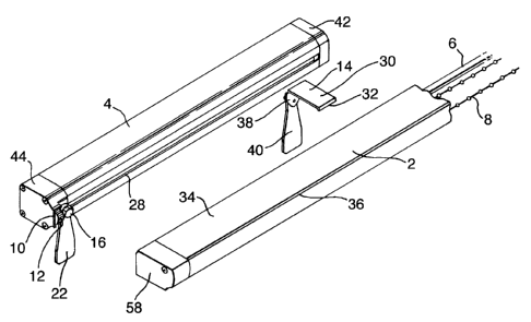
Referring to Figures 1(a) and (b) there is illustrated an end section
of a head rai12 and an associated motor unit 4, together forming a head
rail assembly.
Within the head rail 2 are preferably housed a number of carriages
(not illustrated) each for suspending a vertical blind (also not illustrated).
A tilt rod 6 extends along the length of the head rail 2 and passes through
each of the carriages. By rotating the tilt rod 6, the suspended vertical
blinds may be tilted. A retraction chain 8 also extends up and down the
length of the head rai12. By moving the chain 8, the carriages may be
deployed along or retracted from the length of the head rail 2.
As illustrated, the motor unit 4 is provided as a separate integral
unit. The motor unit is provided with an aperture 10 through which a
toothed drive gear 12 extends. As will be described below, the end of the
head rail 2 is provided with a corresponding aperture allowing the
toothed drive gear 12 to mesh with a control gear in the head rail 2.
CA 02313716 2000-07-11
-11-
In order to attach the motor unit 4 to the head rail 2, there is
provided a clip 14 and a latch 16.
The latch 16 comprises a non-circular head 18 which may be
inserted through a corresponding non-circular opening 20 in the head rail
2. This is illustrated in Figures 2(a), where Figure 2(a) is the cross-
section II-II of Figure 1(b).
By rotating the latch 16 and the non-circular head 18 to the
position illustrated in Figure 2(b), where Figure 2(b) is a cross-section
corresponding to that of Figure 2(a), the latch 16 holds the motor unit 4
in place alongside the head rail 2. Preferably, although not illustrated,
the head 18 also extends rearwardly towards the motor unit 4 such that,
as it is rotated to the position of Figure 2(b), it provides pressure on the
inside of the head rail 2, thereby gripping the head rail 2 closely to the
motor unit 4.
Preferably, as illustrated, the latch 16 is also provided with a
handle 22 which takes a concealed position between the motor unit 4 and
head rail 2 when the latch 16 is in the position holding the motor unit 4 to
the head rail 2.
The, latch 16 may be mounted to the motor unit 4 in any suitable
manner allowing rotation. However, as illustrated in the figures, the
latch 16 has a generally circular head 24 which is rotationally mounted in
the housing 26 of the motor unit 4.
Referring to Figure 3, it will be seen that the housing 26 of the
motor unit 4 is constructed having a lipped channel section 28 along one
side. Hence, preferably, the head 24 of the latch 16 is fitted into the
CA 02313716 2000-07-11
-12-
channel section 28. In this way, the latch 16 is attached to the housing 26
of the motor unit 4 but is allowed freely to rotate.
The handle 22 may be provided with a detent protrusion 23 which
fits into the channel section 28 of the motor unit 4. In particular, when
the latch 16 and handle 22 are rotated to the locked position, the detent
protrusion 23 moves into the channel section 28 to hold the handle 22 in
place.
As illustrated, the clip 14 includes a plate section 30 with a tongue
32. The housing 34 of the head rail 2 is provided with an elongate
groove 36 into which the tongue 32 may be fitted. The clip 14 then has a
latch (not illustrated) similar to latch 16. In particular, on a down turned
section 38 of the plate section 30, a rotatable shaft is provided with a
non-circular head. The non-circular head may be inserted into the lipped
channel 28 of the motor unit 4 and then rotated so as to lie behind the lips
of the channel and secure the clip 14 in place. As with the latch 16, the
clip latch is preferably provided with a head which tightens on to the lips
as it is rotated. As illustrated, a handle 40 is provided for rotating the
clip latch and, as with the handle 22, is concealed between the head rai12
and motor unit 4 when the clip 14 is secured to the motor unit 4. The
handle may also include a detent protrusion.
The housing 34 illustrated in Figures 2(a) and (b) also includes an
elongate groove 37 opposite the elongate groove 36. In this way, the
plate section 30 may have an in-turned section 39 to resiliently fit into
the elongate groove 37 and hence, together with the down turned section
38 and elongate groove 36, more securely grip the housing 34 of the head
rail 2.
CA 02313716 2000-07-11
-13-
Starting from the arrangement of Figure 1(a), the clip 14 is
positioned over the head rail 2 such that its tongue 32 grips the groove
36. The motor unit 4 is then brought along side the head rail 2 and the
head 18 of the latch 16 is inserted through the aperture 20 of the head rail
2 and the head of the clip latch is inserted into the lipped channel 28.
This is illustrated in Figure 1(b). In this position, the clip 14 may still be
moved along the length of the motor unit and head rail 2. Preferably, it is
positioned so as best to support the weight of the motor unit 4.
The handles 22 and 40 are then rotated so as to secure the motor
unit 4 in place. The latch 16 holds the end of the motor unit 4 adjacent
the end of the head rail 2 with the drive gear 12 in engagement.
Furthermore, the weight of the motor unit 4 on the clip 14 is supported
by the plate section 30 on the top of the head rail 2, the tongue 32
preventing the clip 14 slipping around the head rail 2.
Figures 4(a) and (b) illustrate an alternative arrangement for the
motor unit 4 and head rail 2. In particular, in this arrangement, the motor
unit 4 is mounted above the head rail 2 along a different side of the head
rail 2 to that illustrated in Figures 1(a) and (b).
The motor unit 4 can be identical to that used with the arrangement
of Figures 1(a) and (b) and illustrated in Figure 3. In particular, it also
includes the rotatable latch 16 with the handle 22.
The head rail 2 differs from that of Figures 1(a) and (b) only by
the end cap 158. In particular, the end cap 158 illustrated in Figures 4(a)
and (b) includes a non-circular opening 118 through which the non-
circular head 18 of the latch 16 may be inserted. This is illustrated in
more detail in Figure 5(a) which shows the cross-section V-V of Figure
CA 02313716 2000-07-11
-14-
4(b). As with the previous arrangement, by rotating the handle 22, the
motor unit 4 may be locked in place against the head rai12. This is
illustrated in Figure 5(b) which is a cross-section corresponding to that of
Figure 5(a).
The end cap 158 also includes an aperture 116 through which the
toothed drive gear 12 of the motor unit 4 may mesh with a control gear
of the head rail.
As with the previous arrangement, a clip is also provided to attach
the motor unit 4 to the head rail 2. In this case, the clip 114 has down
turned sections 138 and 139 either side of the plate section 130. The
down turned sections 138 and 139 fit into the elongate grooves 36 and 37
so as to secure the clip to the head rai12. On the other hand, an insert
120 is provided to fit into the channe128 of the motor unit 4 and a screw
122 provided to attach the plate section 130 to the insert 120. This is
illustrated in Figure 6 which is the cross-section VI-VI of Figure 4(b).
Considering Figure 3, it will be seen that the motor unit includes a
first end assembly 42 and a second end assembly 44. The first end
assembly in the illustrated embodiment includes a connector for
receiving power and control signals if appropriate for remote control.
The illustrated embodiment also includes two tongues 41 for receiving a
printed circuit board 43. The second end assembly 44 includes a gearing
support structure 46 in which a main motor gear 48 and the drive gear 12
are housed. The motor gear 48 is provided on the drive shaft 50 of the
motor 52 and meshes with the drive gear 12. A cap 54 may be screwed
to the support structure 46 to enclose the gears 48 and 12 and provide
and end surface to the motor unit 4.
CA 02313716 2000-07-11
-15-
Figure 3 also illustrates the provision of an insert 56 which may be
fixed in the lipped channel 28 so as to prevent the head 24 of the latch 16
moving longitudinally along the lip channel 28. The support structure 46
may be provided with means to prevent the latch 16 moving in the
opposite direction.
Behind the end cap 58 of the head rail 2, there may be provided a
drive mechanism as illustrated in Figures 7 and 8.
The drive mechanism incorporates a tilt drive for rotating the rod 6
and a retract drive for rotating the chain 8. In particular, a tilt drive gear
60 rotates a tilt drive 62 connected to the rod 6 and a retract gear 64
rotates a retract drive including a chain wheel 66 and crown gear 68
meshing with gear 70.
The tilt gear 60 and retract gear 64 are provided in a single gear
train by both meshing with an intermediate gear 72. In this way, any of
the tilt gear, retract gear and intermediate gear may be driven by some
drive source, for instance the drive gear 12 described above, in order to
operate both the tilt mechanism and the retract mechanism.
Tongues 59 can be provided to hold the last carriage, in other
words the last vane carrier/traveller.
Considering first the tilt mechanism, drive from the tilt gear 60 is
provided to the tilt drive 62 by means of a transmission comprising a lost
motion mechanism and a clutch mechanism.
As is illustrated in Figure 8, the tilt gear 60 is provided with a shaft
74 having, at its end, a non-circular cross-section end 76, in this case
square. A clutch drive component 78 having an outer cylindrical drive
surface 80 is fitted onto the non-circular cross-section end 76 of the shaft
CA 02313716 2000-07-11
-16-
74. The drive surface 80 may be provided as an integral part of the shaft
74. However, by providing it as a separate component, the material
properties of the drive surface 80 may be chosen independently of those
required for the shaft 74 and tilt gear 60.
A wrap spring 82 is fitted around the drive surface 80 such that it
lightly grips the drive surface 80. The drive component 78 and wrap
spring 82 are then inserted within the tilt drive 62.
As illustrated, particularly with reference to Figure 9, the tilt drive
62 includes an end section 84 which is of a part cylindrical shape. In
particular, the part cylindrical end section 84 surrounds the wrap spring
82 and has tilt surfaces 86,87 adjacent the ends 88,89 of the wrap spring
82.
As will be apparent, when the tilt gear 60 and, hence, the drive
surface 80 are rotated, the wrap spring 82 will also be rotated due to its
frictional engagement with the drive surface 80. In either direction of
rotation, an end 88,89 of the wrap spring 82 will abut a tilt surface 86,87
of the tilt drive 62. The wrap spring is wound and positioned within the
part cylindrical end section 84 such that rotation of an end 88,89 of the
wrap spring 82 against a tilt surface 86,87 will tend to tighten the wrap
spring 82 onto the drive surface 80, thereby increasing the frictional grip
between the wrap spring 82 and the drive surface 80. In this way, the
end 88,89 of the wrap spring 82 will rotate the tilt drive 62.
The lost motion mechanism comprises a series of wheels 90
arranged around the shaft 74. Each wheel 90 has some form of
protuberance or indent which allows it only to rotate to a limited extent
with regard to an adjacent wheel. To reduce the number of wheels
CA 02313716 2000-07-11
-17-
required, it is preferred that the available rotation should be as close to
360 as possible.
Figures 10(a) and (b) illustrate respectively the front and rear sides
of a wheel 90. As illustrated, each wheel includes a pair of
protuberances 92,94 on each side. In particular, at the outer periphery
protuberances 92 are provided in each axial direction and, at the inner
periphery, protuberances 94 are provided in each axial direction.
Furthermore, on the rear side of each lost motion wheel 90, an annular
supporting ridge 95 is provided between the protuberances 92 and 94.
As will be appreciated, the annular supporting ridge 95 acts as a guide
for the protuberances 92,94 of an adjacent lost motion wheel 90 and
assists in maintaining the lost motion wheels 90 in axial alignment.
It will be noted that, in order to provide the lost motion
mechanism, it is not necessary to provide two protuberances on each side
of a wheel 90. However, the provision of two protuberances spreads the
load between adjacent wheels, allows the transmitted torque to be shared
between pairs of protuberances and prevents the wheels from becoming
skew relative to the axis of the shaft 74. In other words, they increase the
abutment surface and thereby reduce/distribute the force on/over each
protrusion.
Although not illustrated, the first of the series of wheels 90 is
either fixed to the housing 96 of the mechanism or provided with a
limited rotation relative to the housing 96 in the same way as to its
adjacent wheel 90. As a result, the last wheel 98 of the series of wheels
can only rotate relative to the housing 96 through a number of turns
determined by the number and nature of the series of wheels 90.
CA 02313716 2000-07-11
-18-
The last wheel 98 is provided with or attached to an extension
member 100. As illustrated in Figure 9, the extension member 100
extends alongside the wrap spring 82 between its two ends 88,89. In
particular, it extends into the gap left by the part cylindrical end section
84 of the tilt drive 62 so as generally to complete the cylinder.
It will be appreciated that when the tilt gear 60, drive surface 80,
wrap spring 82 and tilt drive 62 are rotated, then the extension member
100 and last wheel 98 will also be rotated. However, as mentioned
above, due to the lost motion mechanism, the extension member 100 and
last wheel 98 can only rotate through a limited number of turns relative
to the housing 96. Thus, once the extension member 100 has been
rotated by its maximum number of turns, it will stop and an end 88,89 of
the wrap spring 82 (the trailing end 88,89 which in the respective
direction of rotation is not rotating the tilt drive 62) will abut a wrap
spring release surface 101, 102 of the extension member 100. Further
rotation of the wrap spring 82 will cause the end 88,89 in contact with
the wrap spring release surface 101,102 to be deflected. As will be
appreciated, this deflection will open out the wrap spring 82 and, hence,
release the grip of the wrap spring 82 on the drive surface 80. Thus,
further rotation of the tilt gear 60 and drive surface 80 will result merely
in the drive surface 80 slipping with respect to the wrap spring 82.
Hence, no further drive will be provided to the tilt drive 62.
Considering clockwise rotation of the drive surface 80 and wrap
spring 82 illustrated in Figure 9, the end 88 of the wrap spring 82 will
first abut the tilt surface 86 so as to rotate the part cylindrical end
section
84. At the same time the end 89 will abut the wrap spring release surface
CA 02313716 2000-07-11
-19-
102 of the extension member 100 and rotate the extension member 100.
However, when the lost motion mechanism reaches the end of its
available motion, the extension member 100 will not rotate any further.
Hence, when the wrap spring 82 rotates, it will cause the end 89 to be
deflected against the wrap spring release surface 102. As a result, grip
between the wrap spring 82 and drive surface 80 will be lost and no
further rotation will be transmitted from the end 88 to the tilt surface 86
and part cylindrical end section 84.
Thus, continuous drive to the tilt gear 60 will only result in the tilt
drive 62 being rotated through a predetermined number of turns. Once
those predetermined number of turns have been made, the lost motion
mechanism causes the clutch to release further drive. Hence, the tilt gear
60, even when continuously rotated, will only provide sufficient drive to
tilt slats between their maximum tilt positions.
Similarly, modifications may be made to the clutch mechanism.
For instance, by altering where the ends 88,89 of the wrap spring 82 are
positioned, it is possible that the extension member 100 will make up the
greater extent of the cylinder formed by the extension member 100 and
the part cylindrical end section 84 of the tilt drive 62. Also, the drive
surface 80 may be an internal cylindrical surface with the ends 88,89 of
the wrap spring 82 extending inwardly to drive the tilt drive and be
released by the lost motion mechanism.
Considering now the retract mechanism, a lost motion mechanism
is provided between the retract gear 64 and the retract drive 66,68,70.
As illustrated, this retract lost motion mechanism comprises a
series of wheels 103 similar to the wheels 90 described above. Of
CA 02313716 2000-07-11
-20-
course, as for the lost motion mechanism of the tilt drive, this retract lost
motion mechanism can be constructed in other ways.
The first wheel 104 of the series of wheels is either attached to the
retract gear 64 or is restrained to rotate only to a limited extent relative
to
the retract gear 64. Similarly, the last wheel 106 is attached to the gear
70 or "restrained to rotate only to a limited extent relative to the gear 70.
In this respect, in the illustrated embodiment, the back of gear 70 is
provided with protrusions, one of which 108 is illustrated, to interact
with the protrusions of the last wheel 106.
In this way, rotation of the retract drive 66,68,70 only starts after a
predetermined number of turns of the retract gear 64.
As illustrated, the retract gear 64 is provided with a shaft 110
about which the lost motion wheels 103 may rotate. Furthermore, the
shaft 110 is further provided with an internal cylindrical opening for
receiving and supporting for rotation a shaft 112 of the gear 70.
With regard to the connection between the chain wheel 66 and
crown gear 68, it is proposed to provide an overload clutch. In
particular, the crown gear 68 engages with the chain wheel 66 in such a
way that it will slip given sufficient force. As a result, any forcible
movement of the blind or chain will cause the chain wheel 66 to slip
relative to the crown gear 68 rather than cause damage to the drive
mechanism. This will be described and illustrated further in the
following embodiments.
Figure 11 illustrates an alternative lost motion mechanism for the
retract mechanism. This is illustrated in more detail in Figures 12(a) and
12(b). Similar reference numerals as used in Figures 11 to 13 with the
CA 02313716 2000-07-11
-21-
index ' denote functionally equivalent parts to those explained with
reference to Figures 1 to 10.
The retract gear 64' has attached to it or integral with it a
cylindrical spacer 200. At the distal end of the spacer 200, there is an
intermediate drive component 202. As illustrated, the intermediate drive
component 202 includes a short pivot shaft 204 which pivots in a bearing
aperture 206 in the end of the spacer 200. Thus, the intermediate drive
component 202 is spaced from the retract gear 64' and is able to rotate
relative to the retract gear 64' about the same axis.
A flexible elongate member 208 such as a thin cord or filament is
attached to the intermediate drive component 202 at one end 210. The
other end of the elongate member 208 is attached to the back surface of
the retract gear 64' or to the spacer 200 proximate the back surface of the
retract gear 64'.
Thus, when the retract gear 64' is rotated, it first rotates relative to
the intermediate drive component 202 and wraps the elongate member
208 around the spacer 200. When all of the length of the elongate
member 208 has been taken up around the periphery of the spacer 200,
the end 210 of the elongate member 208 then pulls on the intermediate
drive component 202 so as to rotate it. Upon rotation of the retract gear
64' in the opposite direction, the elongate member 208 will rotate relative
to the intermediate drive component 202 and unwind the elongate
member 208 from around the spacer 200. Upon further rotation, it will
then wrap the elongate member 208 around the spacer 200 in the
opposite direction such that eventually the end 210 of the elongate
CA 02313716 2000-07-11
-22-
member 208 will rotate the intermediate drive component 202 in that
opposite direction.
If the elongate member 208 is attached to the back surface of the
retract gear 64' or to a component attached to or integral with the retract
gear 64', then it is possible for the spacer 200 to be rotatable relative to
the retract gear 64'. The spacer 200 is provided merely for a surface
about which the flexible elongate member 208 may be wrapped so as to
take up its length. Drive between the retract gear 64' and the
intermediate drive component 202 is taken through the flexible elongate
member 208 and it is only necessary that the ends of the elongate
member 208 be attached to the relatively rotatable components. Thus, as
another alternative, the spacer 200 can be formed integrally with the
intermediate drive component 202 and mounted rotationally with respect
to the retract gear 64'.
Drive from the intermediate drive component 202 to the retract
drive 66',88' and 70' as illustrated in Figures 11, 12(a) and 12(b) will be
described below.
It will be appreciated that other similar lost motion mechanisms
can be used in place of that illustrated. For instance, mechanisms
employing a ball travelling in a spiral groove are known whereby motion
is only allowed while the ball travels between the two ends of the spiral
groove.
It should also be appreciated that these various lost motion
mechanism can also be used in place of the lost motion mechanism
described with reference to Figure 8 for the tilt gear arrangement.
CA 02313716 2000-07-11
-23-
Considering overall operation, upon rotation of the gear train
60,64,72 in one direction, drive will immediately be transmitted via the
clutch mechanism of the tilt drive to rotate the slats of the blind in the
relevant direction. However, at this time, the lost motion mechanism of
the retract drive will not transmit any drive to retracting or deploying the
slats. Once the lost motion mechanism of the tilt drive has reached its
full extent, the clutch mechanism of the tilt drive will disengage drive to
tilting the slats. On the other hand, once the lost motion mechanism of
the retract drive has reached its full extent, drive will be provided to
retract or deploy the slats.
It will be appreciated that the lost motion mechanism of the retract
drive should not reach its full extent until the lost motion mechanism of
the tilt drive has reached its full extent and disengaged the clutch.
Preferably, the lost motion mechanism of the retract drive has an extent
which is at least equal or greater than the extent of the lost motion
mechanism of the tilt drive. In particular, so that retraction or
deployment of the slats does not occur immediately at the end of tilting
the slats, a period of no action should preferably be provided. This is
particularly advantageous when the drive mechanism is powered by a
motor, since it will be difficult for a user to precisely control the motor to
stop its operation at the changeover between tilt drive and retract drive.
Referring again to Figures 11, 12(a) and 12(b), it will be seen that
an additional drive mechanism exists between the intermediate drive
component 202 and the retract output gear 70'. In particular, a planet
gear 212 transmits drive from the intermediate drive component 202 to
the output gear 70'. The planet gear 212 includes a pivot shaft 214 which
CA 02313716 2000-07-11
-24-
pivots in a bearing aperture 216 in the intermediate drive component 202.
As can be seen from the figures, the aperture 216 is offset from the
axis of the intermediate drive 202 such that rotation of the intermediate
drive 202 causes the planet gear 212 to move along a circular path.
The retract output gear 70' is of annular form with inwardly facing
teeth 218. The outwardly facing teeth 220 of the planet gear 212 mate or
mesh with the inwardly facing teeth 218 of the gear 70'.
The planet gear 212 is also provided with two radially extending
arms 222a and 222b. The arms 222a and 222b fit into corresponding
openings 224a and 224b in the housing 96' such that the planet gear 212
is only able to rotate by a limited amount relative to the housing 96'.
In operation, when the retract mechanism is operated and the
intermediate drive 202 is rotated, the planet gear 212 is moved in a
circular path around the retract output gear 70'. Since the planet gear 212
is restrained from rotation by the arms 222a and 222b, the interference
between its outwardly facing teeth 220 and the inwardly facing teeth 218
of the output gear 70' causes the output gear 70' to rotate.
With reference to Figure 13, when the intermediate drive 202
moves the pivot shaft 214 in a clockwise circular path, the planet gear
212 attempts to rotate anti-clockwise about its own axis. However, upon
such rotation, the upper arm 222a will abut the left side of the opening
224a and the lower arm 222b will abut the right hand wall of the opening
224b. With the planet gear 212 restrained in this manner, further
movement of the planet gear 212 in its circular path will cause the output
gear 70' to rotate.
CA 02313716 2000-07-11
-25-
Similarly, anti-clockwise movement of the planet gear 212 about
its circular path will cause it to rotate clockwise about its own axis until
the arms 222a and 222b abut the opposite walls of the openings 224a and
224b.
In contrast, when an attempt is made to rotate the gear 70' to
transmit motion back through the mechanism, the mechanism locks up.
Thus, the weight of the slats or pulling of the slats in either direction will
not operate the mechanism and the slats will be held securely in place.
When an attempt is made to rotate the output gear 70', the mating
gears 218 and 220 attempt to rotate the planet gear 212 about its own
axis, i.e. rotating shaft 214 in aperture 216. However, in the same way as
described above, the arms 222a and 222b abut walls of the openings 224a
and 224b so as to prevent such rotation. In this way, the planet gear 212
is unable to move any further and, in particular, is not moved around the
circular path required to move the intermediate drive 202.
Of course, this mechanism will also have the same effect in
various other configurations, for instance with the planet gear on the
outside of an output gear having outwardly facing teeth. Similarly, the
planet gear 212 will transmit rotation from the intermediate drive 202 to
the output gear 70' or lock up whenever it is restrained from rotation
relative to the housing. However, it could be allowed to rotate through a
limited extent between these two situations. For instance, the planet gear
212 could be limited to rotate by nearly a complete revolution.
It should be appreciated that this mechanism could be used with or
without the lost motion and single drive mechanisms described above.
Similarly, it could be used in conjunction with the tilt drive.
CA 02313716 2000-07-11
-26-
As illustrated, the output gear 70' meshes with a crown gear 68'
which in turn engages a chain wheel 66'. As described above for the
previous embodiment, the chain wheel 66' mates with the crown gear 68'
to form an overload clutch. In particular, the mating part of the crown
gear 68' is provided with a series of radial protrusions which are of
generally rounded shape. The corresponding inwardly facing portions of
the chain wheel 66' are formed as resilient bridge pieces which extend
over recesses and are, therefore, radially outwardly deflectable. Thus, if
the chain whee166' is forcibly rotated relative to the crown gear 68', the
bridge pieces are able to deflect and allow relative rotation between the
chain whee166' and the crown gear 68'. In this way, forcible movement
of the blind or chain will cause relative rotation between the chain wheel
66' and the crown gear 68' rather than damaging the drive mechanism.
Of course, the mating surfaces of the chain wheel 66' and crown gear 68'
could be reversed with the resilient parts being provided on the crown
gear 68. Indeed, other forms of overload clutch could also be used.
Figures 14 to 18 illustrate an alternative embodiment to that of
Figures 11, 12 and 13. Similar reference numerals as used in Figures 14
to 18 with-the index " denote functionally equivalent parts to those
explained above with reference to Figures 11 to 13.
In particular, the planet and crown gear mechanism is replaced by
a worm gear mechanism and the second lost motion mechanism of the
retract drive is arranged coaxially with the first lost motion mechanism
of the tilt drive. The assembled mechanism is illustrated in Figure 16.
As illustrated, in this embodiment, the tilt gear 60 or 60' of the
previous embodiments acts as the sole drive gear 60". A retraction drive
CA 02313716 2000-07-11
-27-
take-off gear 300 is provided coaxially with the drive gear 60" and
rotatably on the shaft 74" of the drive gear 60". The lost motion
mechanism for the retract drive is then provided by means of a flexible
elongate member 208" similar to that of the previous embodiment which
extends between the drive gear 60" and the retraction drive take-off gear
300. Hence, in this embodiment, the shaft 74" fulfills the function of the
spacer 200 of the previous embodiment.
Rotation of the retraction drive take-off gear 300 is transferred to
the pinion end 302 of a worm gear 304 by means of an intermediate gear
306. Thus, rotation of the retraction drive take-off gear 300 results in
rotation of the worm gear 304.
As will be apparent from the figures, rotation of the worm gear
304 causes rotation of the mating worm wheel 308 and, hence, also the
chain wheel 66".
By virtue of this worm gear arrangement, forces, for instance
resulting from the weight of the blind are not transmitted back through
the mechanism. In other words, the blind will remain where positioned
despite forces acting on it.
Similarly to the previous embodiments, mating parts of the worm
wheel 308 and chain wheel 66" provide an overload clutch. In this way,
if the blind or retract chain 8" is forcably moved, for instance beyond one
of its end positions, the chain wheel 66" is able to slip relative to the
worm wheel 308 and prevent the mechanism from being damaged.
Since, compared to the previous embodiments, the chain wheel is
provided vertically on the side of the mechanism, the housing 96" is
provided with an opening which is filled by a chain wheel cover 310.
CA 02313716 2000-07-11
-28-
Otherwise, this embodiment is generally similar to the previous
embodiments with a plurality of lost motion wheels 90" driving a last
wheel 98" and the tilt drive 62". It will be appreciated that the shaft 74"
has, at its end, a non-circular cross-section end 76" which mates with the
clutch drive component 78". As illustrated, this cross-section includes 8
protrusions.
For embodiments using the elongate flexible member 208, it is
noted that particularly suitable cord materials would include high tensile
strength yarns such as KEVLAR or NOMEX, both by DuPont,
TWARON by Akzo-Nobel, DYNEEMA by DSM or SPECTRA by
Allied Fibres. Such materials have tensile strengths in the range of 28 to
35 grams per denier. In particular, Ultra-High Molecular Weight
Polyethylene (UHMW-PE), such as DYNEEMA or SPECTRA, has a
tensile strength exceeding that of steel and has flexibility and fatigue
resistance superior to Aramid fibres, such as KEVLAR, TWARON or
NOMEX products. The first mentioned highly sophisticated
polyethylene material is particularly suitable for high load applications
and is also often referred to as High Modulus Polyethylene (fflVIPE) or
High Molecular Density Polyethylene (IIlVIDPE).
Referring again to the overall construction, since the drive
mechanism includes a single drive train 60,64,72,60',64',72',60" for
operating both the tilt drive and retract drive, a drive source may be
meshed with the gear train at any position.
Figures 19 and 20 correspond to the arrangement of Figures 1 and
2. In particular, the end cap 58 in which the drive mechanism is
provided includes an opening 114 through which the drive gear 12 may
CA 02313716 2000-07-11
-29-
mesh with the tilt gear 60. However, as described with reference to
Figures 4, 5 and 6, it may be preferred to mount the motor unit 4 on top
of the head rail 2. In this case, as illustrated in Figures 21 and 22, the
end cap 58 includes an opening 116 on its upper surface such that the
drive gear 12 can mesh with the intermediate gear 72. As illustrated in
Figure 7, the mechanism housing 96 preferably includes the non-circular
opening 118 for receiving the non-circular head 18 of the latch 16. In
this way, the relative positioning of the drive gear 12 and intermediate
gear 72 can be secured.
For convenience the end cap 58 may be provided with both the
opening 114 and 116. Additional components may be provided for
filling or closing these openings when not in use.
It will be appreciated that the drive mechanism described with
reference to Figures 7 and 8 could be used in conjunction with a manual
cord operation. Indeed, a manual cord unit including a gear to mesh with
the drive train 60,64,72 could be provided to attach to the head rail as a
separate unit in place of the motor unit 4.
It will also be appreciated that the drive mechanism could be used
to operate 'horizontal slats. Indeed, the head rai12 could be mounted
vertically in order to control horizontal slats.