Note: Descriptions are shown in the official language in which they were submitted.
CA 02313720 2000-07-11
Doc No. 10-159 CA Patent
An Optical Coupling Arrangement
Field of the Invention
This invention relates generally to the coupling of light from an optical
waveguide end, to
one or more other optical waveguides via an at least partially reflective
optical element.
Background of the Invention
to It is common practice to couple light from an optical waveguide such as an
optical fibre
to one or more optical fibres via an at least partially transmissive,
partially reflective
optical element. For example a dichroic filter is often disposed between a
pair of
collimating/focusing lenses such as graded index (GRIN) lenses to provide a
wavelength
division multiplexing (WDM) function. Fig. 1 illustrates a prior art WDM
filter, wherein
15 wavelengths of light ~,1 and ~,2 are launched into a first port at an end
face of a GRIN
lens 12a and wherein light of wavelength ~,1 is reflected from a filter 14
which passes
light of wavelength ~.2. The lines indicating the path of the beam as it is
partially
reflected and partially transmitted through the filter represents a ray
through the centre of
the beam launched into the lens 12a. Figs. 2 and 3 illustrate the beam's shape
and path for
20 light launched into a port along the optical axis of the lens and for light
launched into a
port offset from the optical axis respectively.
Prior art Fig. 4 illustrates a typical arrangement of one side of a WDM filter
wherein an
optical fibre tube 8 holding to optical fibres at predetermined locations is
shown optically
25 coupled with an adjacent GRIN lens 12c which is juxtaposed to a filter 14.
Fibre tubes or
sleeves of this type provide a convenient way of holding to or more optical
fibres a fixed
distance apart such that the pair of fibres can then be moved without damaging
them.
Furthermore, the tube allows the fiber ends (and tube) to be polished such
that the end
face is slanted to lessen the effects of unwanted back reflections.
CA 02313720 2000-07-11
Doc No. 10-ls9 CA Patent
Heretofore, there has been no known reason to align pairs of optical fibres at
the slanted,
polished end face of the sleeve in any special orientation except with regard
to pairs of
optical fibres being offset a same distance from the optical axis. The term
pair relates to
two optical fibre which via some reflective element are optically coupled to
one another.
Prior art Fig. 13 illustrates pairs of optical fibres (A,B), (C,D), and (E,F)
disposed at a
slanted end face of a fibre tube 8. By placing a reflective element at an
appropriate
location and position, and by providing an appropriate collimating/focusing
lens, light
from one of each of the pairs will couple into the other of the pair in an
expected fashion.
to What is unexpected, is that if the fibres are located at any locations
other than along one
particular line through the optical axis, coupling will be negatively
affected. For example
the positioning of the pair of optical fibres shown in Fig. 5 is least
favourable for
optimum coupling in a WDM filter. This is illustrated in more detail in Fig.
6, where the
path AC and the path CB are of different lengths illustrated by OL due to the
position of
1 s the fibres on the slanted end face of the sleeve 8.
Fig. 7 more clearly illustrates the problem with haphazardly disposing the
fibre
equidistant from the longitudinal axis of the sleeve or more importantly from
a line
extending from the optical axis of the lens 12d wherein a beam leaving the
output fibre at
2o point A is perfectly collimated at the reflective surface 16 through point
C, and wherein
the reflection from 16 is focused at point D along the dashed line 18, instead
of being
focused at point B coincident with the optical fibre end.
It is an object of this invention to provide an arrangement of optical fibres
within a tube
2s or sleeve that will couple light in an optimum manner.
It is a further object of this invention to provide an optical system wherein
a preferred
coupling is achieved with essentially no additional components from previous
similar
coupling methods.
CA 02313720 2002-09-25
Doc No. 10-159 CA Patent
Summary of the Invention
In accordance with the invention, there is provided, a WDM filter comprising:
a first optical fibre tube having two or more optical fibres securely held
therein in a
predetermined relationship;
a second optical fibre tube having at least one optical fibre contained
therein, the second
optical fibre tube being optically aligned with ane of the two or more optical
fibres
contained in the first optical fibre tube; an inwardly facing end face of the
first optical
fibre tube being slanted so as to reduce the effects of back reflections, the
slanted end
l0 face having a slant of less than 15 degrees and greater than 2 degrees from
a line
orthogonal to a longitudinal axis of the optical fibre tube;
collimating/focusing lenses disposed between the first and second optical
fibre tubes, the
collimating lens having an optical axis;
an at least partially reflective optical filter disposed between the
collimating/focusing
lenses;
end faces of the two or more optical fibres being fixed along a line at the;
end face of the
slanted tube at locations equidistant from the longitudinal axis of the lens
and at locations
such that light launched from one of the at least two optical fibre end faces
is collimated
at a collimating location at or near the optical filter and such that
collimated light at the
2o collimating location is focused at another of the at least two optical
fibre end faces, the
line being substantially perpendicular to the longitudinal axis of the second
optical fibre
tube.
In accordance with the invention, there is provided, an optical filter
comprising:
a wavelength dependent at least partially reflective optical filter;
an optical fibre tube having two optical fibres securely held therein in a
predetermined
relationship, a cross-section of the optical fibre tube through a longitudinal
axis thereof
delineating an end face disposed toward the at least partially reflective
optical filter that is
slanted with respect to a line normal to the longitudinal axis of the optical
fibre tube, the
slant angle being between 2 and 10 degrees, wherein end faces of the at least
two optical
CA 02313720 2002-09-25
Doc No. 10-159 CA Patent
fibres lie on a line across the end face of the tube being a shortest line
across the slanted
end face of the tube through the longitudinal axis.
In accordance with the invention, there is further provided, a WDM filter
comprising:
first and second back-to-back collimating/focusing lenses each having an
optical axis;
a filter element disposed between the back-to-hack lenses,
a first sleeve having a longitudinal axis that is parallel with the optical
axis of the first
lens, the first sleeve being adjacent the first lens and having two optical
fibres securely
held in a fixed relationship therein, end faces of the fibres and the first
sleeve being cut
and or polished to slant to lessen the unwanted effects of back reflections;
the slanted end faces of the fibres being fixed on a line that is
substantially perpendicular
to the longitudinal axis of the sleeve.
In accordance with the invention, there is yet further provided, an optical
filter
comprising:
an optical fibre tube for securely holding two or more optical fibres therein
in a fixed
relationship, an inwardly facing end face of the optical fibre tube being
slanted so as to
reduce the effects of back reflections, the slanted end face having a slant:
of less than 15
degrees and greater than 2 degrees from a line orthogonal to a longitudinal
axis of the
optical fibre tube;
a collimating/focusing lens disposed adjacent the slanted end of the optical
fibre tube, the
collimating/focusing lens having an optical axis;
an at least partially reflective optical element disposed adjacent the
collirnating/focusing
lens, end faces of the two or more optical fibres being disposed along a line
on the slanted
end face at locations equidistant from the longitudinal axis of the optical
fibre tube and at
locations such that light launched from one of two or more optical fibre end
faces is
collimated at a collimating location at or near the optical filter and such
that collimated
light at the collimating location is focused at another of the two or more
optical fibre end
faces, the line on the slanted end face being substantially perpendicular to
the
o longitudinal axis of the optical fibre tube.
CA 02313720 2000-07-11
Doc No. 10-159 CA Patent
Brief Description of the Drawings
Exemplary embodiments of the invention will now be described in conjunction
with the
drawings in which:
Fig. 1 is a side view of a prior art WDM optical filter for separating or
combining two
wavelengths of light;
Fig. 2 is a side view of the prior art WDM optical filter shown in Fig. 1;
Fig. 3 is a side view of the prior art WDM optical filter shown with 2 ports;
Fig. 4 is a side view of an optical filter wherin the optical fibre sleeve and
adjacent GRIN
lens have complementary reciprocal slanted end faces for lessening the effect
of back
1 o reflections;
Fig. 5 is an isometric view of a prior art optical fibre tube illustrating the
slanted end face;
Fig. 6 is an isometric view of the tube shown in Fig. 5 including an optical
filter disposed
a distance away;
Fig. 7 is a view of the tube shown in Figs. 5 and 6 illustrating a focal point
being a
15 distance away from the end face of a receiving optical fibre;
Fig. 8 is an isometric view of an optical filter system in accordance with the
invention,
where the drawbacks of the circuit of Fig. 7 have been obviated by disposing
the end
faces of the optical fibres along a particular line along the slanted end face
of the optical
fibre tube;
2o Fig. 9 is a detailed illustration of the end face of the optical fibre tube
shown in Fig. 8;
Fig. 10 is a detailed illustration of an end face of an optical fibre tube in
accordance with
the invention wherein four optical fibre are shown disposed at locations along
a line
which forms a shortest diameter across the slanted end face of the optical
fibre tube;
Fig. 11 is a prior art sleeve having pairs of optical fibres disposed
locations on opposite
25 sides of the longitudinal axis;
Fig. 12 is a side view of an optical filter system in accordance with the
invention;
Fig. 13 is an end view of a prior art optical fibre sleeve wherein fibres are
disposed
around the longitudinal axis of the sleeve; and,
Fig. 14 is a view of the sleeve and lens arrangement in accordance with this
invention.
CA 02313720 2000-07-11
Doc No. 10-159 CA Patent
Detailed Description
The following description, it should be understood that same elements shown in
different
figures are assigned same reference numerals. Referring now to FIG. 1, a 0.25
pitch
GRIN lens 12a is shown having an input beam represented by an line with a
directional
arrow at an input end face 12. Fiber lenses of this type are produced under
the trade name
"SELFOC"; the mark is registered in Japan and owned by the Nippon Sheet and
Glass
to Co. Ltd. At an end face of the quarter pitch GRIN lens the input beam
becomes
collimated. Another matched quarter pitch GRIN lenses 12b is disposed in a
back to
back relationship with the lens 12a. Each GRIN lens is provided with a port
which is a
point or region along an end face of the lens for receiving or transmitting a
beam of light.
A dichroic filter 14 is disposed between the two GRIN lenses and is shown to
filter light
of wavelength ~,1, by reflecting it backwards to a second port on the end face
of the
GRIN lens 12a. Light of wavelength ~.2 is passed through the filter to an
output port on
the outwardly facing end face of the lens 12b. Improvements to this well know
filter
arrangement have been made over the years. Fig. 4 illustrates an improvement
wherein a
fibre tube is present for securely holding the two optical fibres therein in a
fixed spaced
2o relationship; furthermore, the mutually facing end faces of the fibre tube
8 and GRIN
lens 12c have complementary slanted end faces, with a polished slant of
approximately
6° to lessen the effects of unwanted back reflections. Fig. 5 is
another view of the end
foace of the fibre tube 8 illustrating the relative position of the end faces
of optical fibres
contained within the sleeve 8, at positions A and B, with respect to the
slanted end face.
Turning now to Fig. 6, another drawing shows the locations A and B of the
fibre ends at
the slanted end face of the fibre tube 8, and shows an optical filter 14 a
distance away.
For clarity, the lens is not shown in this figure, however would be required
to provide a
collimated beam at the filter 14 end face. What is noticeable in Fig. 6, is
that the distance
3o from location A to location C is not equal to the distance from location C
to location B.
Fig. 7 illustrates inherent problem with this prior art design, shown in Figs
5, 6, and 7.
6
CA 02313720 2000-07-11
Doc No. 10-159 CA Patent
Since the distance AC in not equal to AB when light is launched from location
A to the
filter at location C, it becomes collimated at the filter. However collimated
light reflected
from the filter becomes focused at a location D, short of the location B.
Hence at location
after location D, the beam begins to diverge and is not focused at the end
face of the
optical fibre at location B. This phenomenon is subtle, as was discovered when
monitoring and analyzing the light received using the prior art circuit shown
which was
not being efficiently coupled into the receiving optical fibre.
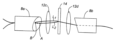
Fig. 8 illustrates a preferred embodiment of the invention, wherein optical
fibre ends at
locations A and B oriented 90 degrees offset from the orientation shown in
Figs. 5, 6, and
7 provide locations equidistant from the filter 14. It should understood that
optical fibre
tubes, or sleeves are customarily round in cross-section, however tubes that
are square,
triangular, rectangular, or other polygonal shapes can be envisaged and are
within the
scope of this invention. However, when fibre sleeve having a round cross-
section is
polished at an end, for example at an angle of 6 degrees, the end face becomes
spherical,
and the diameter of the end face is larger if taken along its longest axis 91
and is shorter
across its shorter axis 90 orthogonal to the longer axis shown in Fig. 9. Fig.
10 is an
alternative embodiment of the invention wherein four optical fibre ends are
shown at
locations A1, Bl and A2, B2; once again, the fibre end faces are at locations
that define a
line across the slanted face such that light launched from A 1 directed to B 1
is collimated
at a distant filter after passing through a collimating lens (not shown in
this figure) and is
focused at the receiving fibre end at B1. In contrast, prior art Fig. 11, and
Fig. 13 define
fibre locations at a slanted end face of the tube that suffer from the
aforementioned
focusing or collimating problems of prior art Fig. 7.
Fig. 12 illustrates an entire filtering system in accordance with this
invention.
Refernng now to Fig. 14, a sleeve having its end face polished at 6 degrees
from the
normal to the longitudinal axis (LA) of the sleeve is shown, wherein the fibre
end faces
denoted by x are also polished with a same slant. The line shown through the
two ends x-
3o x is orthogonal to the LA of the sleeve and OA of the lens. Hence, the
fibre end faces are
7
CA 02313720 2000-07-11
Doc No. 10-159 CA Patent
slanted and lie on a line that is orthogonal to the OA of the lens or LA of
the sleeve. This
novel arrangement provides preferred coupling of light from and into the fibre
end faces.
Of course numerous other embodiments may be envisaged without departing from
the
spirit and scope of the invention.