Note: Descriptions are shown in the official language in which they were submitted.
CA 02313864 2000-09-15
-1-
COLD DRAWING APPARATUS
This invention relates to a cold drawing apparatus
adapted to, in a process for making a fibrous web, cool and draw
a plurality of melt spun filaments.
Japanese Patent Application Disclosure No. 1995-109658
describes a process for making a patterned fibrous web
comprising a spinning step of discharging a plurality of
continuous filaments from a spinning nozzle extending
transversely of an apparatus onto a collecting conveyor
travelling below the spinning nozzle to form the patterned
fibrous web on the conveyor. An apparatus for static
filamentation participates in the spinning step.
The apparatus for static filamentation is adapted to
charge the filaments with static electricity so that these
charged filaments may be spaced one from another under a
repulsion generated among them. The filaments may be charged
with electricity over a desired width, for a desired period and
at a desired voltage in accordance with a predetermined program
to provide the fibrous web with a predetermined pattern.
The process described in the Japanese Patent Application
Disclosure No. 1995-109658 requires the apparatus for static
filamentation adapted to a command from a programmed computer
CA 02313864 2000-09-15
-2-
and thereupon to apply the filaments with voltage. Use of such
apparatus for static filamentation correspondingly increases
a manufacturing cost of the fibrous web.
This invention aims to provide a cold drawing apparatus
requiring no apparatus for static filamentation to charge the
filaments with static electricity and thereby enabling a
patterned fibrous web to be made at a relatively low cost.
According to this invention, there is provided a cold
drawing apparatus interposed in a system for making a fibrous
web and having an inlet for a plurality of melt spun continuous
filaments, an outlet for the filaments and a pair of side walls
extending between the in- and outlets and opposed to and spaced
from each other in a transverse direction orthogonal to a
direction in which the filaments are fed to define a passage
therebetween so that the filaments are cooled and drawn as the
filaments pass through the passage defined between the opposed
side walls, wherein: at least one of the opposed the walls is
formed with a plurality of crests extending in the transverse
direction at predetermined intervals and a plurality of troughs
each extending between each pair of adjacent the crests.
In one preferred embodiment of this invention, the crests
are formed on both of the side walls at regular intervals in
CA 02313864 2000-09-15
-3-
the transverse direction so that the crests on one of the side
walls are respectively opposed to the crests on the other side
walls and wherein the troughs are formed on both of the side
walls at regular intervals in the transverse direction so that
the troughs respectively extend in fan shapes and the troughs
on one of the side walls are respectively opposed to the troughs
on the other side wall.
In another embodiment of this invention, a value
corresponding to the minimum dimension of the passage defined
between each pair of the opposed crests divided by the minimum
dimension of the passage defined between each pair of the
opposed troughs is in a range of 0.1 - 0.7.
In still another embodiment of this invention, a
dimension of the crest as measured in the transverse direction
is in a range of 10 - 100 mm and a dimension of the trough as
measured in the transverse direction is in a range of 10 - 100
mm.
In further another embodiment of this invention, at least
one of the side walls is formed with an air supply opening lying
between the inlet and a region having the crests and troughs
to supply compressed air toward the outlet.
In further additional embodiment of this invention, the
apparatus is adapted to be oscillated in the transverse
CA 02313864 2000-09-15
-4-
direction.
Fig. 1 is a perspective diagram illustrating a system for
making fibrous web including a perspective view of an apparatus
according to this invention;
Fig. 2 is a sectional view of the apparatus taken along
line A - A in Fig. 1 partially eliminated;
Fig. 3 is a sectional view of the apparatus taken along
line B - B in Fig. 1;
Fig. 4 is a sectional view of the apparatus taken along
line C - C in Fig. 1; and
Fig. 5 is a sectional view of the fibrous web made by the
apparatus taken along line D - D in Fig. 1.
Details of a cold drawing apparatus according to this
invention will be more fully understood from the description
given hereunder with reference to the accompanying drawings.
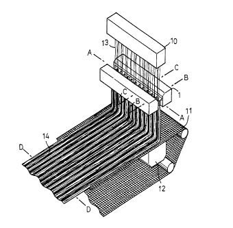
Fig. 1 is a perspective diagram illustrating a system for
making a fibrous web 14 including a perspective view of a cold
drawing apparatus 1 according to this invention in which the
fibrous web 14 and a conveyor 11 are partially eliminated. The
system includes a spinning nozzle 10 adapted to discharge a
plurality of continuous filaments 13, a cold drawing apparatus
CA 02313864 2000-09-15
-5-
1 adapted to cool and draw the melt spun filaments 13 , a netlike
collecting conveyor 11 adapted to collect the filaments 13 thus
cooled and drawn, and an air suction mechanism 12 lying below
the conveyor 11 to establish an air stream sucked from an upper
side toward a lower side of the conveyor 11. The nozzle 10,
the apparatus 1 and the conveyor 11 are spaced one from another
by predetermined distances. The nozzle 10 discharges a
plurality of filaments 13 at a substantially constant rate and
with a substantially uniform basis weight.
The filaments 13 discharged from the nozzle 10 pass
through the apparatus 1 in. which the filaments 13 are cooled
and at the same time drawn before these filaments 13 leave the
apparatus 1. The filaments 13 having left the apparatus 1 are
collected on the conveyor 11 to form fibrous web 14 on the
conveyor 11. Though not shown, the filaments 13 are intertwined
one with another by ejecting high pressure water streams to the
fibrous web 14 on the conveyor 11 or by punching the fibrous
web 14 with needles having barbs, or the filaments 13 are
heat-bonded one with another by subjecting the fibrous web 14
to hot blast or the filaments 13 are bonded one to another by
means of adhesive to form a desired nonwoven fabric.
Fig. 2 is a sectional view of the apparatus taken along
a line A - A in Fig. 1 as partially eliminated and Figs. 3 and
CA 02313864 2000-09-15
-6-
4 are sectional views of the apparatus taken along lines B -
B and C - C in Fig. 1, respectively. In Figs. 2, 3 and 4,
illustration of the filaments 13 is eliminated. The apparatus
1 has an inlet 2 for the filaments 13, an outlet 3 for the
filaments 13, side walls 4 extending between the inlet 2 and
the outlet 3 transversely of the direction in which the
filaments 13 are discharged and opposed to each other, and an
air supply opening 9 provided in the vicinity of the inlet 2
to supply compressed air toward the outlet 3.
The side walls 4 of the apparatus 1 define therebetween
passages 7, 8 for the filaments 13. The apparatus 1 cools the
filaments 13 by air stream supplied from the air supply opening
9 into the passages 7, 8 and simultaneously stretches the
filaments 13 as these filaments 13 pass through the passage 7,
8.
Each of the side walls 4 of the apparatus 1 is formed with
a plurality of crests 5 extending at regular intervals
transversely of the direction in which the filaments 13 are fed
and a plurality of troughs 6 extending at regular intervals also
transversely of the aforesaid direction. The crests 5 on one
of the side walls 4 are opposed to the crests 5 on the other
side wall 4 and the troughs 6 on one of the side walls 4 are
opposed to the troughs 6 on the other side wall 4. Each of the
CA 02313864 2000-09-15
crests 5 is shaped in a semispherical projection having a
cross-section describing a circular arc which is convex
inwardly of the passage 7. Each of the troughs 6 extending in
a fan shape between each pair of the adjacent crests 5. The
crests 5 are round and therefore free from generation of a
turbulence in the air stream flowing through the passages 7.
Accordingly, the crests 5 are effective to prevent a stream of
the filaments 13 from being disturbed.
The minimum dimension L1 of the passage 7 defined between
each pair of opposed crests 5 is smaller than the minimum
dimension L2 of the passage 8 defined between each pair of
opposed troughs 6 , An air pressure alternately rises and drops
as air supplied from the supply opening 9 passes through the
passages 7 defined between the respectively opposed crests 5
and the passages 8 defined between the respectively opposed
troughs 6. Specifically, the air pressure rises in the passages
7 defined between the respectively opposed crests 5 due to a
pressure drag by the crests 5 and drops in the passages 8 defined
between the respectively opposed troughs 6. A velocity of the
air flow decreases in the passages 7 defined between the
respectively opposed crests 5 in which the air pressure is
relatively high and increases in the passages 8 defined between
the respectively opposed troughs 6 in which the air pressure
CA 02313864 2000-09-15
_g_
is relatively low.
The amount of the filaments 13 discharged from the nozzle
and passing through the passages 8 defined between the
respectively opposed troughs 6 is larger than the amount of the
filaments 13 passing through the passages 7 defined between the
respectively opposed crests 5 since the velocity of air flow
is higher in the passages 8 than in the passages 7. Because
of such difference in the velocity of air flow, the filaments
13 are stretched at a higher stretch ratio as they pass through
the passages 8 and the filaments 13 are stretched at a lower
stretch ratio as they pass the passages 7. With a consequence,
the filaments 13 passing through the passages 8 have a fineness
smaller than the filaments 13 passing through the passages 7.
Of the filaments 13 collected on the conveyor 11, those having
passed through the passages 8 defined between the respective
opposed troughs 6 present a density and a bulk higher than those
having passed through the passages 7 defined between the
respectively opposed crests 5. In this manner, the finished
fibrous web 14 is obtained which is formed with a pattern
comprising a plurality of stripes extending longitudinally of
the fibrous web 14.
In the apparatus 1, a value corresponding to the minimum
dimension L1 of the passage 7 defined between each pair of
CA 02313864 2000-09-15
-9-
opposed crests 5 divided by the minimum dimension L2 of the
passage 8 defined between each pair of opposed troughs 6 is
preferably in a range of 0.1 - 0.7. The value less than 0.1
would lead to a problematic situation in which the dimension
L1 of the passage 7 defined between each pair of opposed crests
is excessively smaller than the dimension L2 of the passage
8 defined between each pair of opposed troughs 6. In this
situation, the filaments 13 would crowd in the passages 8 and
the filaments 13 passing through the passages 7 defined between
the respectively opposed crests 5 would have a correspondingly
small basis weight. As a result, regions of unacceptably low
density may be generated in the fibrous web 14. The value
exceeding 0.7, on the other hand, would unacceptably reduce a
difference in the dimensions L1, L2 of the passages 7, 8 and
therefore correspondingly reduce a difference in .the velocity
of air flow in these passages 7, 8. Consequently, the finished
fibrous web 14 as a whole would have a substantially uniform
density and sometimes it would be impossible to form the fibrous
web 14 with a desired pattern.
In the apparatus 1, each crest 5 has its transverse
dimension L3 preferably of 10 - 100 mm and each trough 6 has
its transverse dimension L4 preferably of 10 - 100 mm. These
dimensions L3, L4 less than 10 mm would, depending on a flow
CA 02313864 2000-09-15
-10-
rate and a flow velocity of air supplied, lead to a situation
in which the number of both the crests 5 and the troughs 6 are
excessively increased and they are arranged at excessively
close intervals. As a result, air streams flowing these
passages would be apt to interfere one with another and to
generate a turbulence in the passages 7, 8 or a wake in the
vicinity of the outlet 3. These factors would disturb the
stream of the filaments 13 and make it impossible to form a
distinct pattern on the fibrous web 14. The dimensions L3, L4
exceeding 100 mm, on the other hand, each pair of adjacent crests
as well as each pair of adjacent troughs 6 would be spaced
from each other by a distance too large to form a finely striped
pattern on the fibrous web 14.
If the dimension L3 of each crest 5 is smaller than 10
mm and the dimension L4 of each trough 6 is larger than 100 mm,
the filaments 13 would crowd into the passages 8 defined between
the respectively opposed troughs 6 and the filaments 13 passing
through the passages 7 defined between the respectively opposed
crests 5 would be of a correspondingly small basis weight. In
a consequence, regions of excessively low density would be
generated in the fibrous web 14. If the dimension L3 of each
crest 5 exceeds 100 mm and the dimension L4 of each trough 6
is less than 10 mm, on the contrary, the filaments 13 passing
CA 02313864 2000-09-15
-11-
through the passages 7 defined between the respectively opposed
crests 5 would have a basis weight correspondingly increased
so far as the amount of the filaments 13 discharged from the
nozzle 10. The basis weight of the filaments 13 passing through
the passages 7 would sometimes increase until a differential
basis weight between the filaments 13 passing through the
passages 7, 8 would substantially become zero and no distinct
striped pattern would appear on the fibrous web 14.
It is possible without departing from the scope of this
invention to oscillate the apparatus 1 transversely thereof,
i . a . , in a direction indicated by a double-headed arrow X - X'
in Fig . 2 so that the f fibrous web 14 may be formed with a pattern
comprising a plurality of stripes extending in a zigzag
direction. The apparatus 1 may be moved in any one of the
directions indicated by the double-headed arrow X - X' to form
a striped pattern extending obliquely to the longitudinal
direction of the fibrous web 14.
Fig. 5 is a sectional view of the fibrous web 14 taken
along a line D - D in Fig. 1. The fibrous web 14 has regions
14a in which the filaments 13 have relatively high density and
bulk and regions 14b in which the filaments 13 have relatively
low density and bulk. The regions 14a protrude upward with
respect to the regions 14b and these regions 14a, 14b both
CA 02313864 2000-09-15
-12-
extending longitudinally of the fibrous web 14 define a striped
pattern on the fibrous web 14.
It is possible without departing from the scope of this
invention to exploit the cold drawing apparatus 1 in a manner
that, instead of providing the air supply opening 9, an air
suction mechanism is provided below the apparatus 1 and thereby
an air flow is generated. A temperature of air supplied may
be at a room temperature or a temperature lower than the room
temperature. Each of the crests 5 may be shaped so as to present
not only the semicircular cross-section but also the other
cross-sectional shape such as semi-ellipse, obelisk or
triangle.
The filaments 13 may be of thermoplastic synthetic resin
such as polyolefine, polyester or polyamide. It is also
possible to use elastomer made of thermoplastic synthetic resin.
Such elastomer includes those made of polyolefine, polyester,
polyamide and polyurethane.
The cold drawing apparatus apparatus according to this
invention enables the patterned fibrous web to be made at a low
cost without using an apparatus for static filamentation
adapted to charge the filaments with static electricity.
The dimensions of the passages defined between the
respectively opposed crests and the passages between the
CA 02313864 2000-09-15
-13-
respectively opposed troughs as well as the transverse
dimensions of the crests and troughs may appropriately varied
to obtain the fibrous web in which the filaments have a density
and a bulk correspondingly varied. The fibrous web can be
formed thereby optionally with a fine striped patter or a rough
striped pattern.